Ed Nisley's Blog: Shop notes, electronics, firmware, machinery, 3D printing, laser cuttery, and curiosities. Contents: 100% human thinking, 0% AI slop.
Tag: Improvements
Making the world a better place, one piece at a time
The manual accompanying my OMTech 60 W CO₂ laser clearly states it has a 1.5 inch focus lens:
OMTech laser packing list – 1.5 inch focus lens
Which I had always assumed was the case, even though a short lens like that would typically be used for fine engraving due to its smaller spot size. One could argue the carton should have included a 1.5 inch lens in addition to whatever was in “its optics”, but it didn’t.
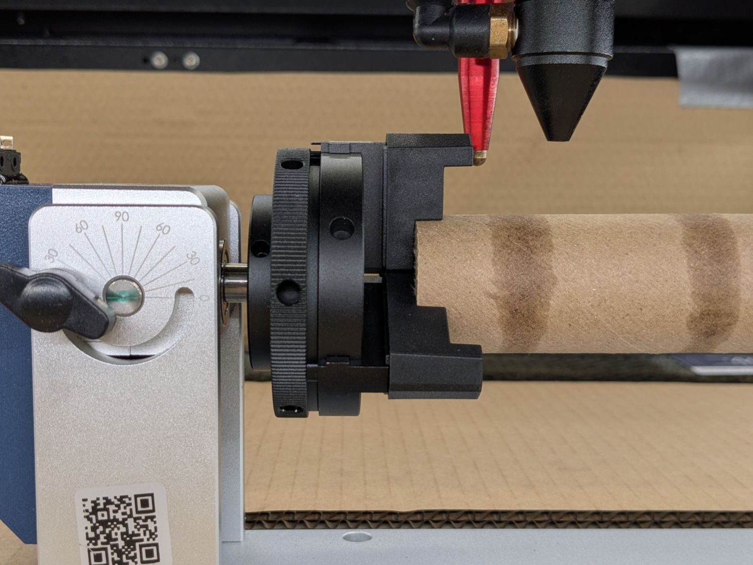
It has a 2 inch lens, as I confirmed while switching to a 3 inch lens to get more clearance over the Ortur rotary than the stock lens allows:
Ortur Chuck Rotary – 2 inch focus lens
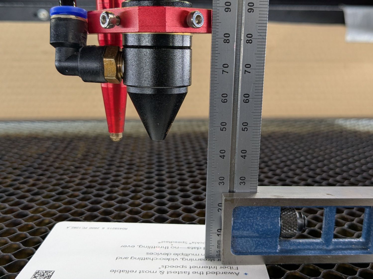
The bottom of the lens (its planar surface) sits inside the nozzle at (about) the same level as the joint just above the assist air fitting:
OMTech laser – 3 inch lens focus distance
That’s the proper focus distance for the 3 inch lens, with the lens 3 inch = 3 × 25.4 = 76.2 mm above the platform. There’s obviously some room for quibbling about the optical center of the lens vs. the lower surface and so forth and so on, but a ramp test shows it’s Close Enough™:
Ramp Test – 3inch lens – 2025-12-29
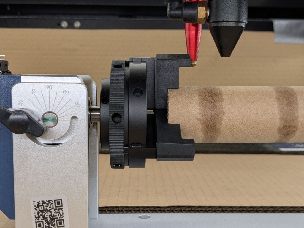
Which adds an inch of clearance, enough to prevent obvious collisions:
Ortur Chuck Rotary – 3 inch focus lens
Changing the lens requires removing the air fitting, during which operation I also moved the clamp holding the focus pen. Because that changed where the switch trips, the Focus Distance also changed:
2 inch lens = 12.7 mm
3 inch lens = 12.7 + 25.4 = 38.1 mm
The clearance under the nozzle depends only on the lens:
2 inch lens = 18.5 mm
3 inch lens = 18.5 + 25.4 = 43.9
I’ve been using step gauges for manual focusing with the 2 inch lens:
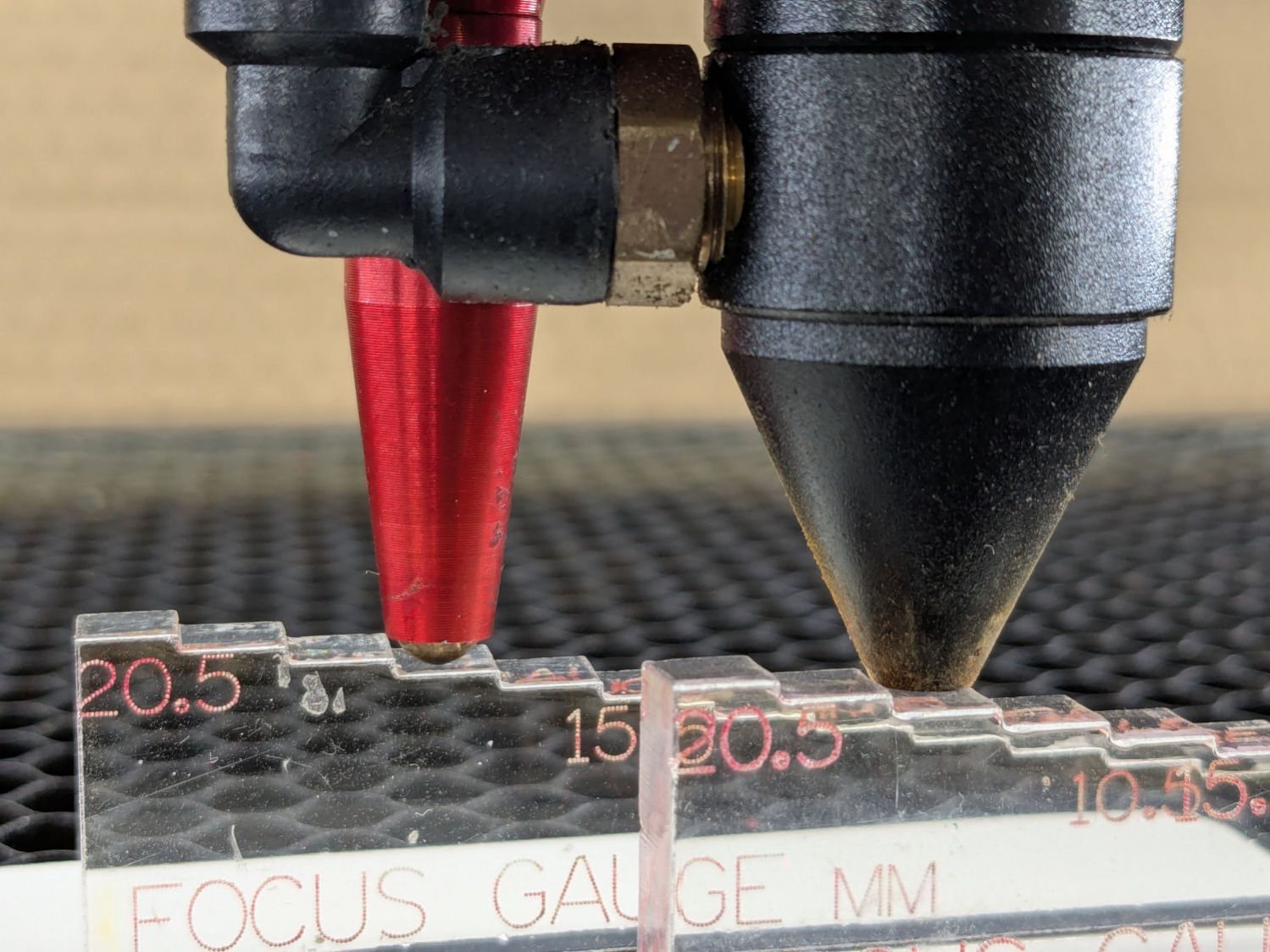
OMTech focus pen – tripped vs nozzle
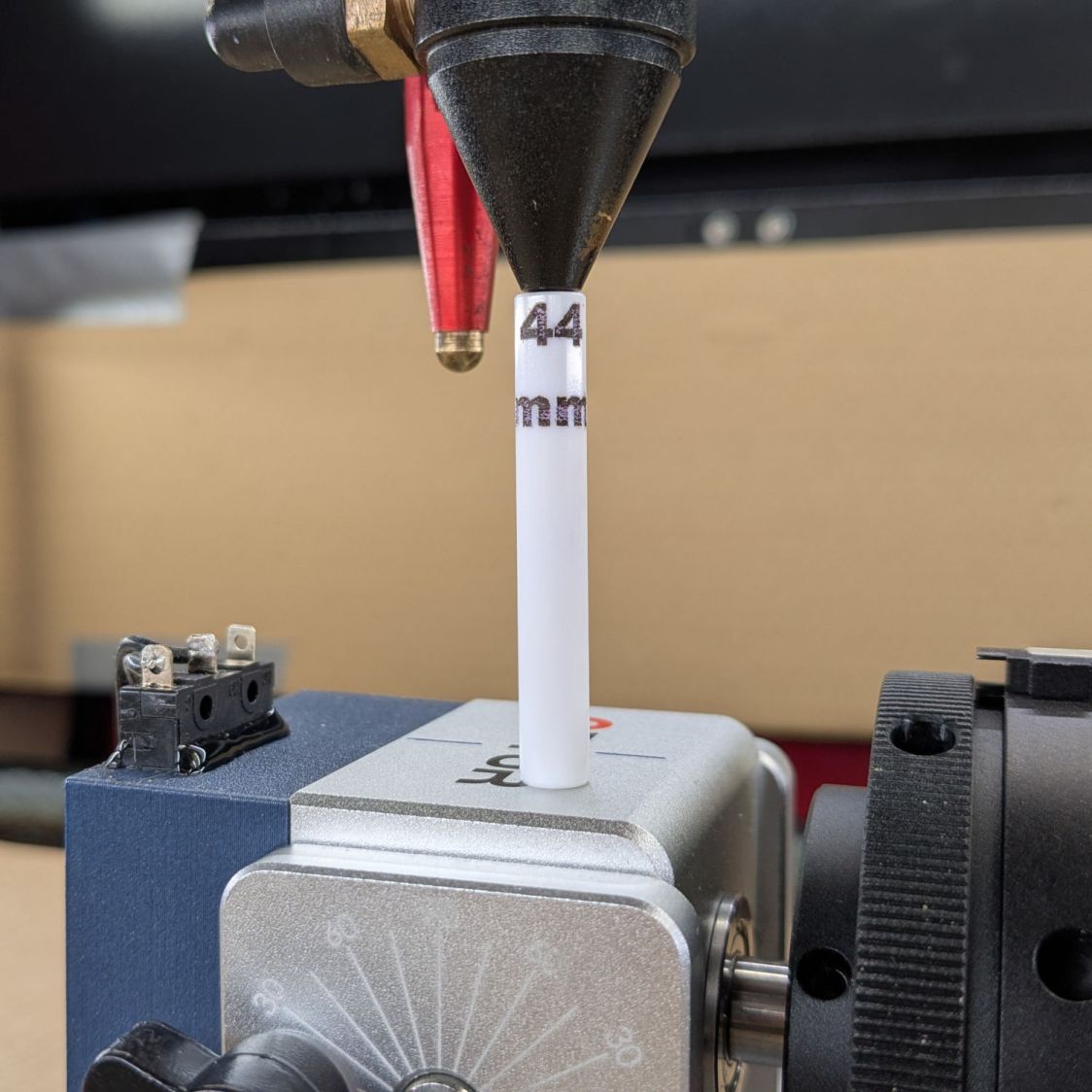
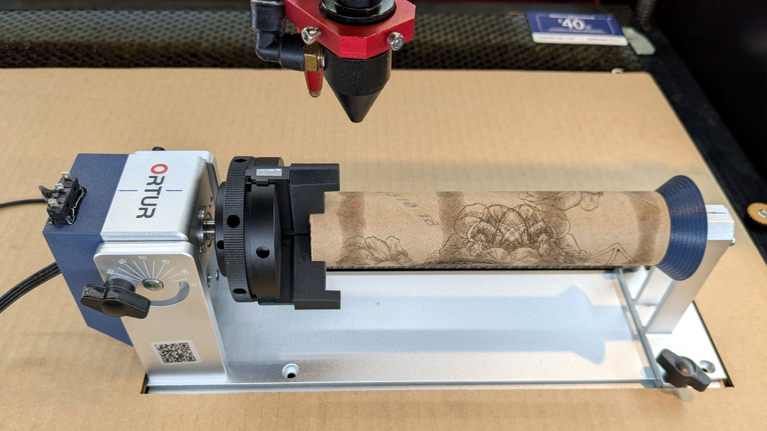
I figured a rod would be more appropriate for the 3 inch lens and, hey, now that I have a rotary, I can engrave it:
OMTech laser – 3 inch lens focus stick
Through no fault of mine at the lathe, that stick is exactly 43.9 mm long, but “44 mm” fit better.
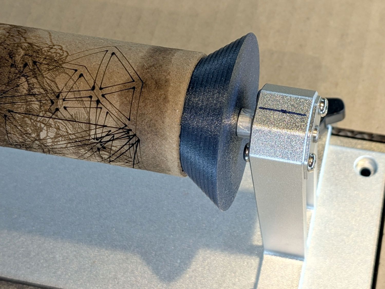
A conical (a.k.a. bullnose) center in the tailstock simplifies supporting cylindrical objects:
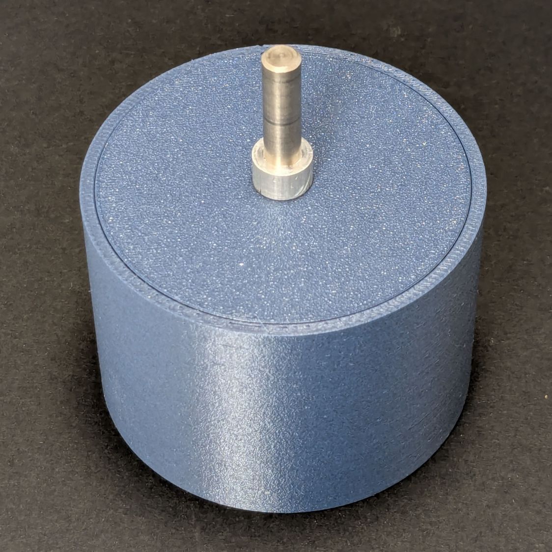
Ortur Chuck Rotary conical center – installed
The spring-loaded tailstock bearing has a 5 mm bore. The bullnose rests against a small spacer on its 5 mm shaft to hold it away from the bearing’s mounting screws with some bearing spring compression. I turned the spacer from aluminum rod because lathe work is satisfying, but a printed spacer would work fine.
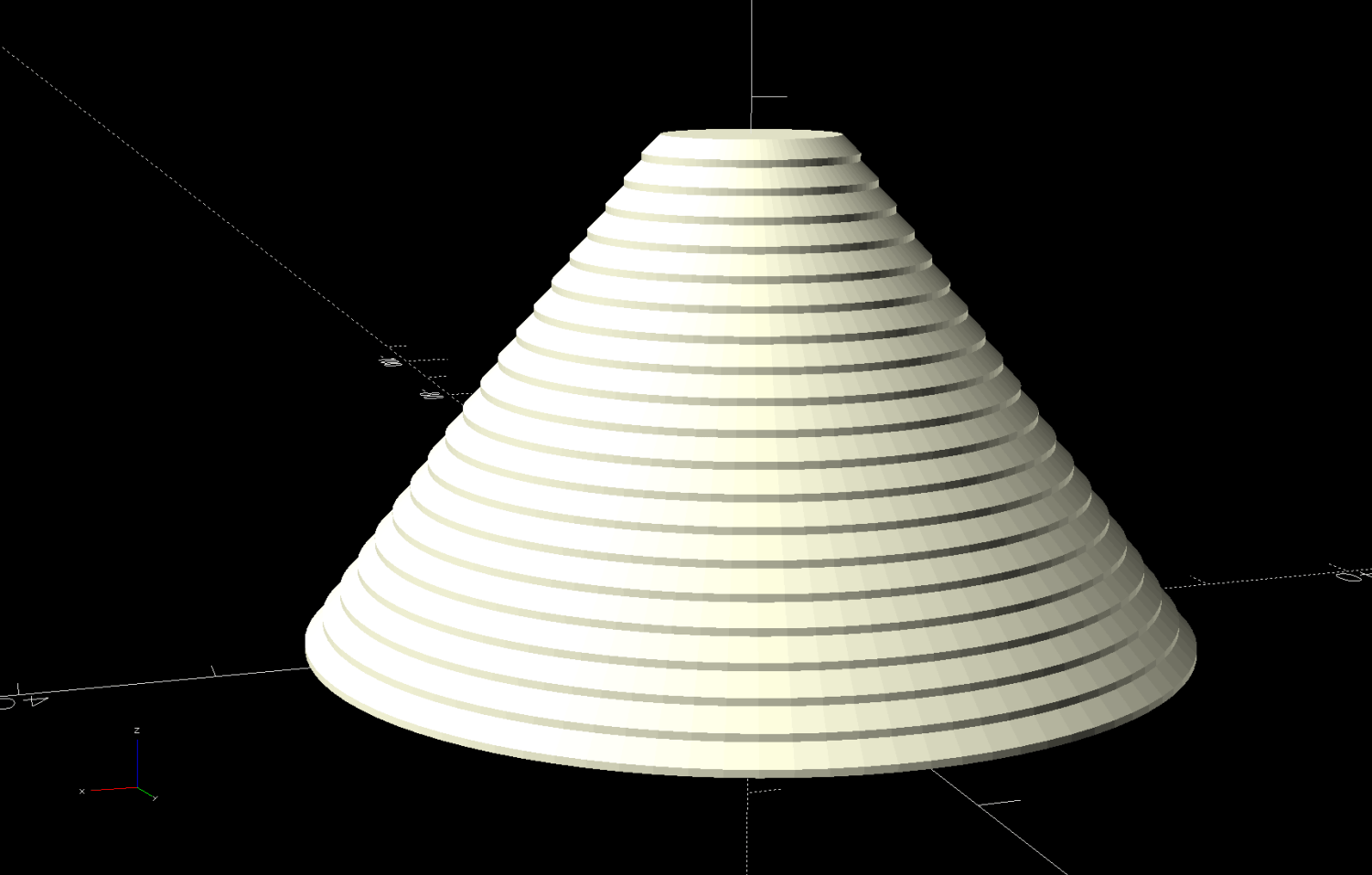
The bullnose is a cone with steps encouraging the cylinder to sit properly:
Ortur Rotary Conical Center – 10-50mm
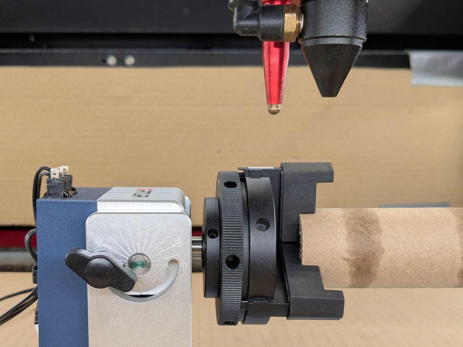
With both ends centered, the cylinder sits concentric with the chuck axis:
Ortur Chuck Rotary home switch – jaw position
The chuck grabs the OD and the bullnose supports the ID, so removing crud from both ends is in order.
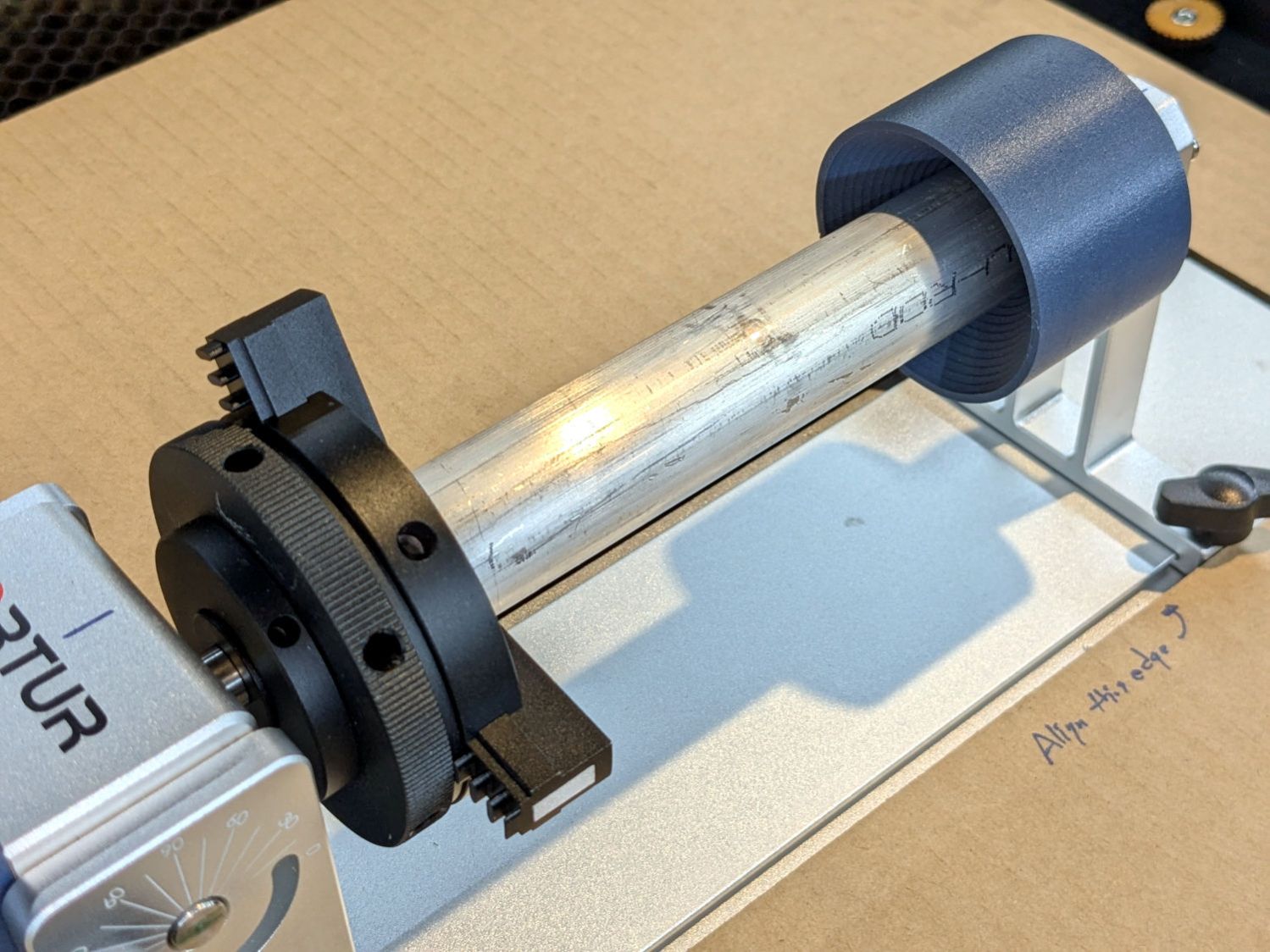
The bullnose won’t work for a solid rod, so a negative cone = cup center may come in handy:
Ortur Chuck Rotary cup center – installed
Stipulated: A CO₂ laser will bounce right off a solid aluminum rod. Imagine I chucked up a wood dowel, OK?
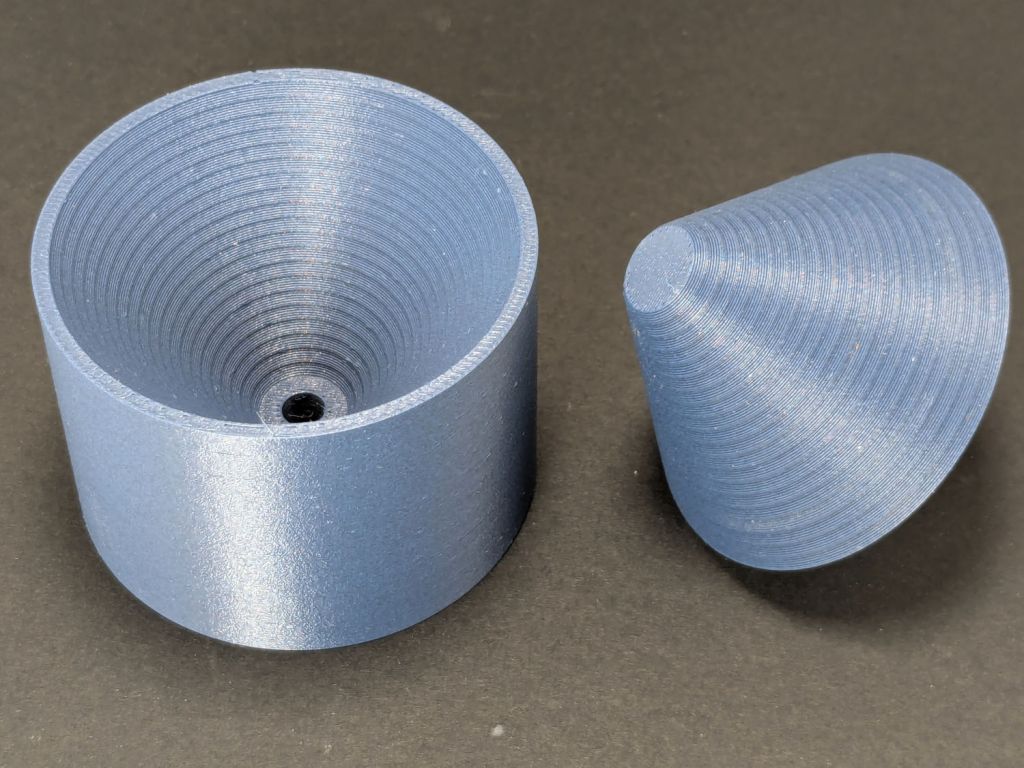
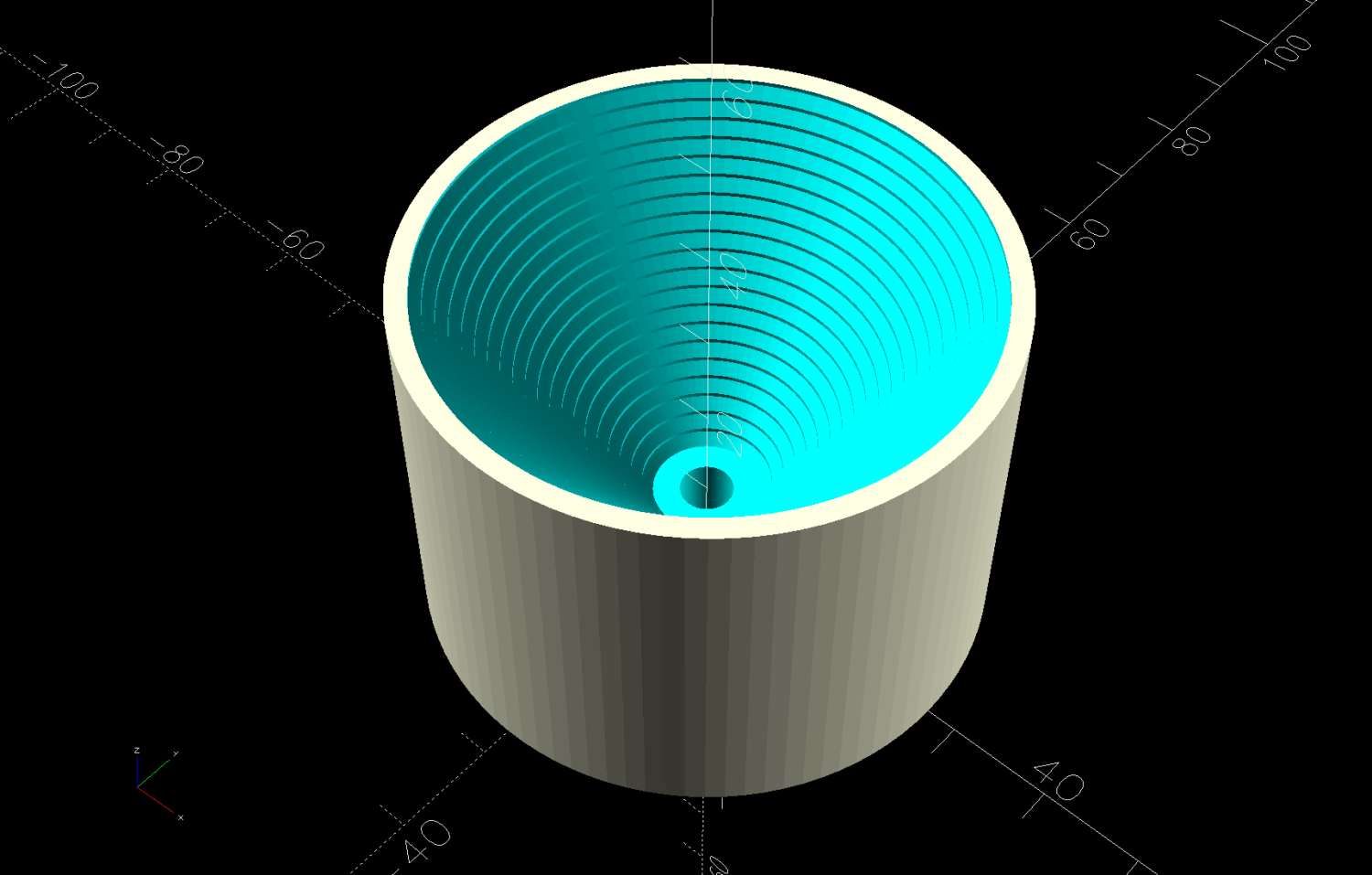
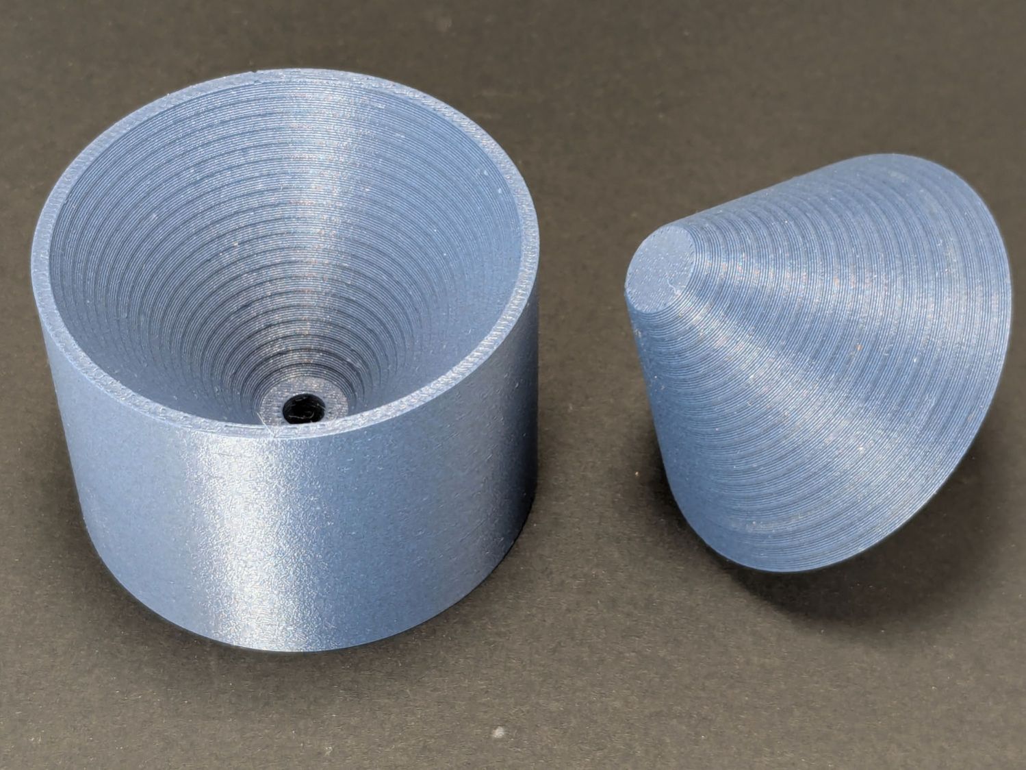
A cup center is what remains afteryoinking a bullnose out of a cylinder:
Ortur Rotary Conical Centers – cup
Looks like I did exactly that:
Ortur Chuck Rotary conical centers
Somewhat surprisingly, the two parts nest perfectly:
Ortur Chuck Rotary conical centers – nested
That’s without the shaft installed on the cup, so they won’t sit quite so neatly on the shelf.
Aligning the rotary axis along the laser’s X axis and setting the focus requires attention to detail, but a decent tailstock center makes that effort meaningful.
This file contains hidden or bidirectional Unicode text that may be interpreted or compiled differently than what appears below. To review, open the file in an editor that reveals hidden Unicode characters.
Learn more about bidirectional Unicode characters
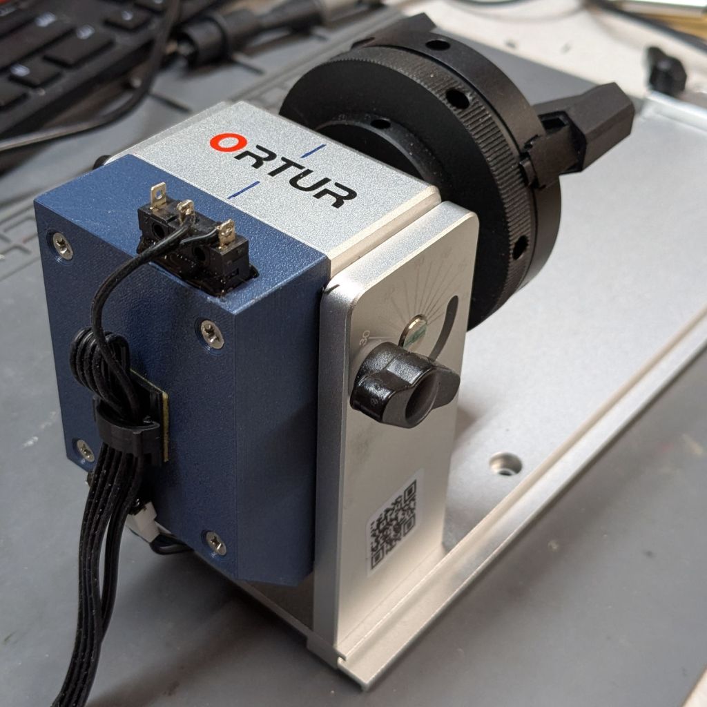
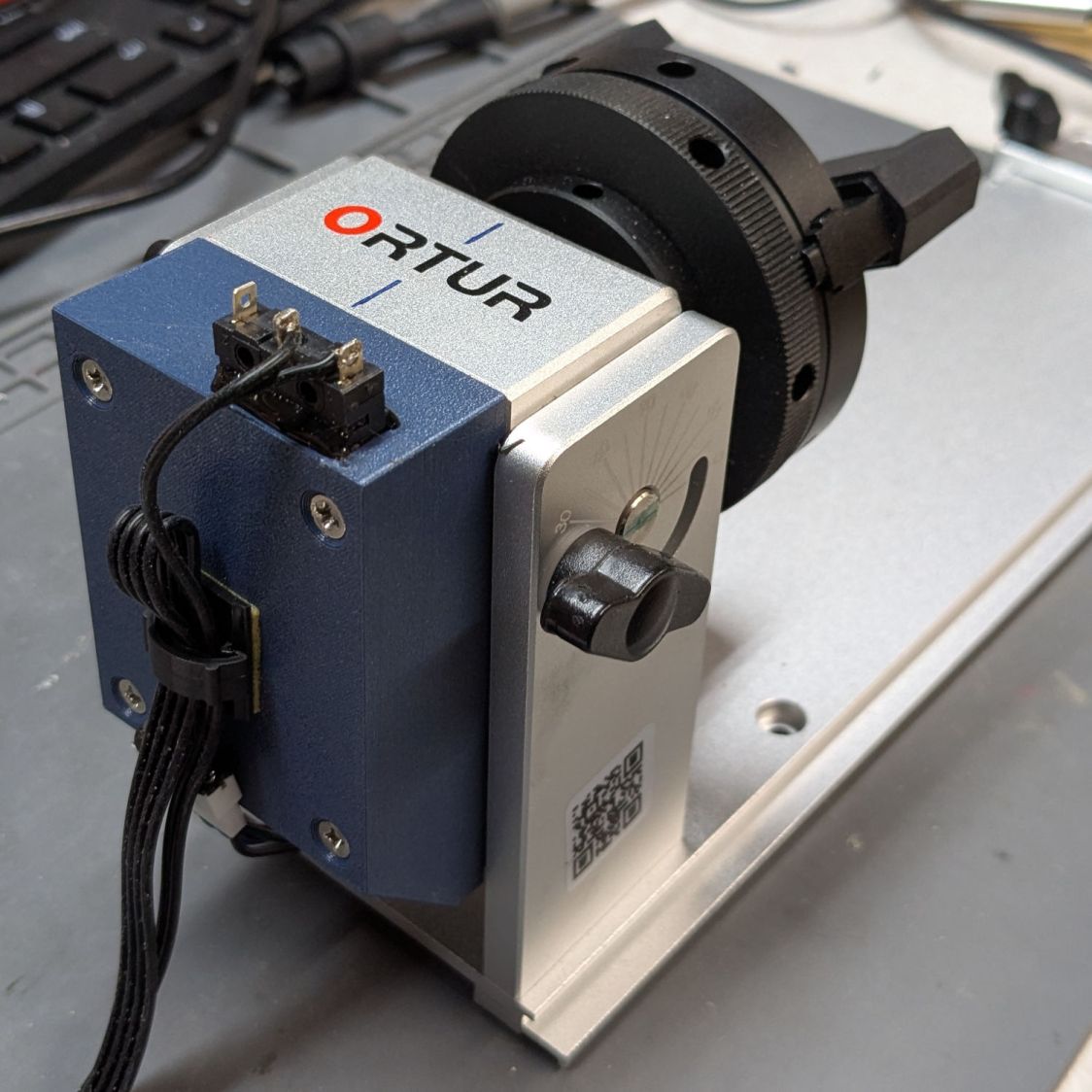
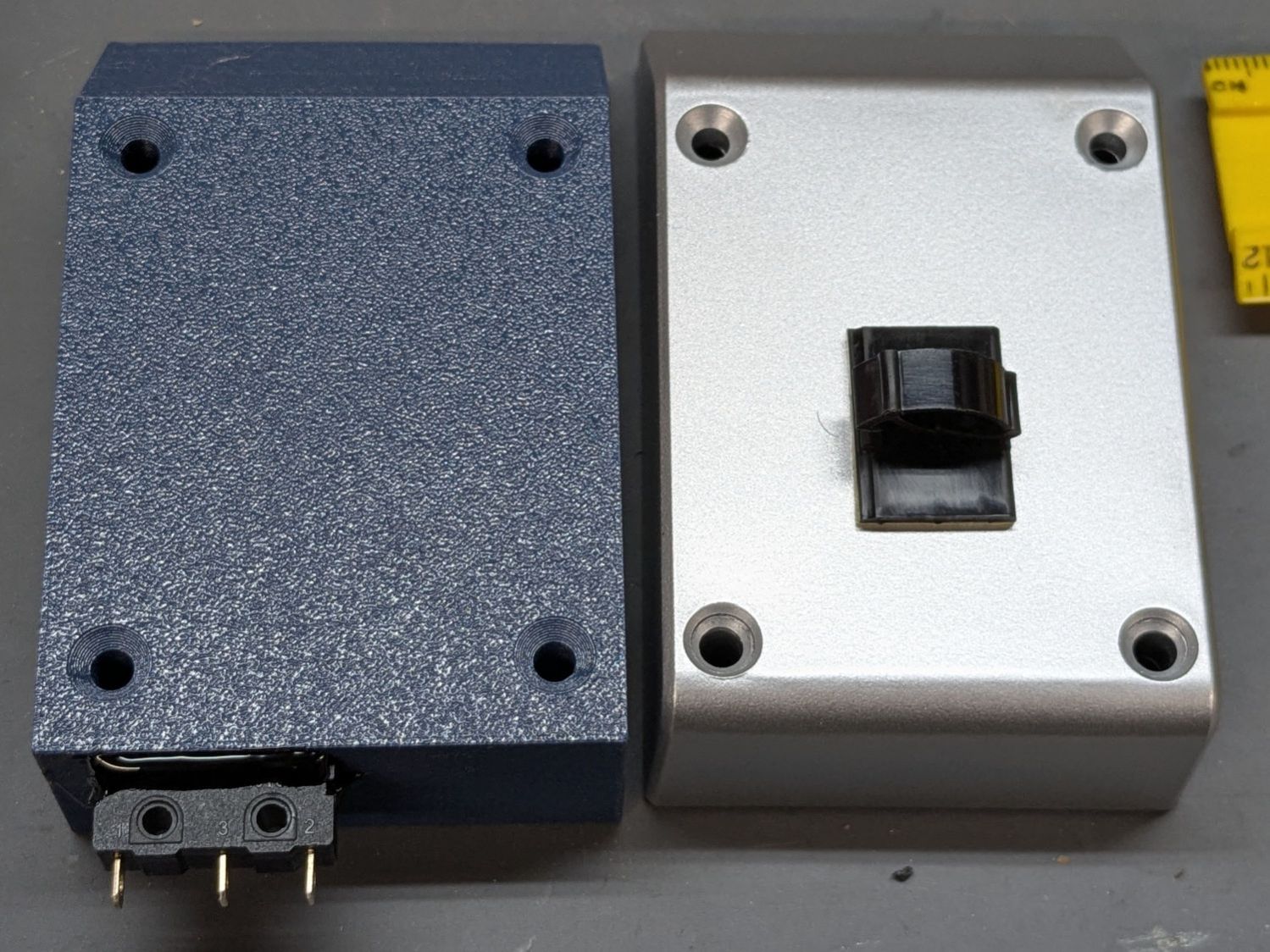
Two beads of hot melt glue hold the switch flush along the cover’s inside surface:
Ortur Chuck Rotary home switch – case exterior
One might argue for a tidy cover over those terminals.
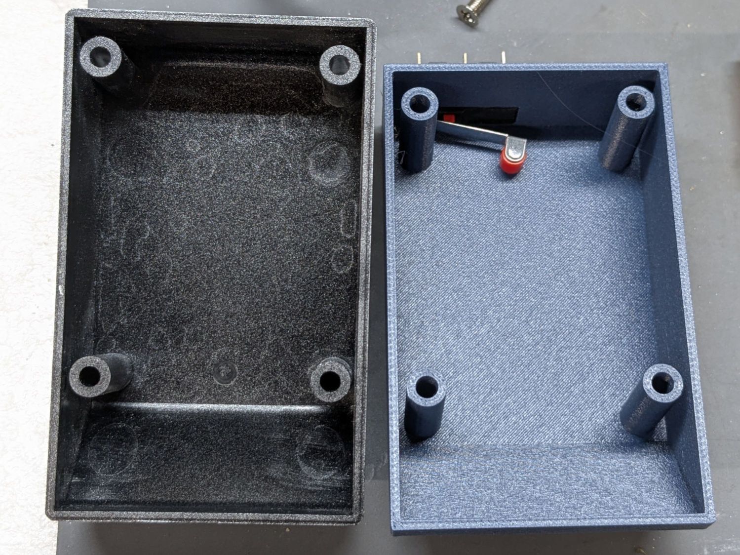
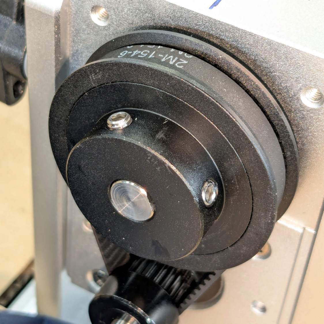
While contemplating the layout by holding the switch here & there, seeing the switch roller neatly centered on the pulley hub told me the Lords of Cosmic Jest favored this plan:
Ortur Chuck Rotary home switch – case interior
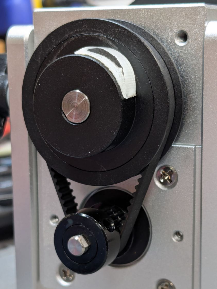
A simple cam lifts the roller:
Ortur Chuck Rotary home switch – pulley cam
That’s obviously laser-cut acrylic sitting on double-sided tape.
Edit: The pulley ratio is 1:3, so the step/rev value is three times the DIP switch setting on the stepper driver.
Some finicky repositioning put the #1 chuck jaw on top after homing:
Ortur Chuck Rotary home switch – jaw position
A more permanent adhesive under the cam may be in order.
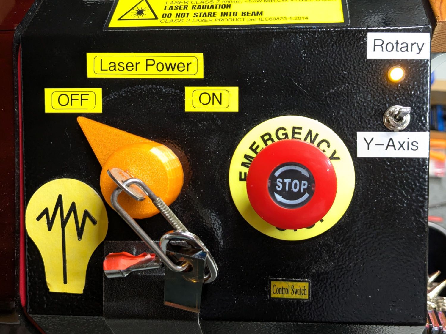
Wiring the normally open switch contacts in parallel with the existing Y axis home switch lets both the gantry and the rotary trigger the controller. The front-panel switch ensures only one of those two can move:
Laser Rotary – control switch
With all that in place and the switch flipped, the chuck rotates happily and homes properly with the controller in normal linear mode.
Spoiler: A Ruida-ish KT332N controller ignores the Y-axis Home enable setting with Rotary mode enabled, because everybody knows a rotary has no need for a home switch.
This file contains hidden or bidirectional Unicode text that may be interpreted or compiled differently than what appears below. To review, open the file in an editor that reveals hidden Unicode characters.
Learn more about bidirectional Unicode characters
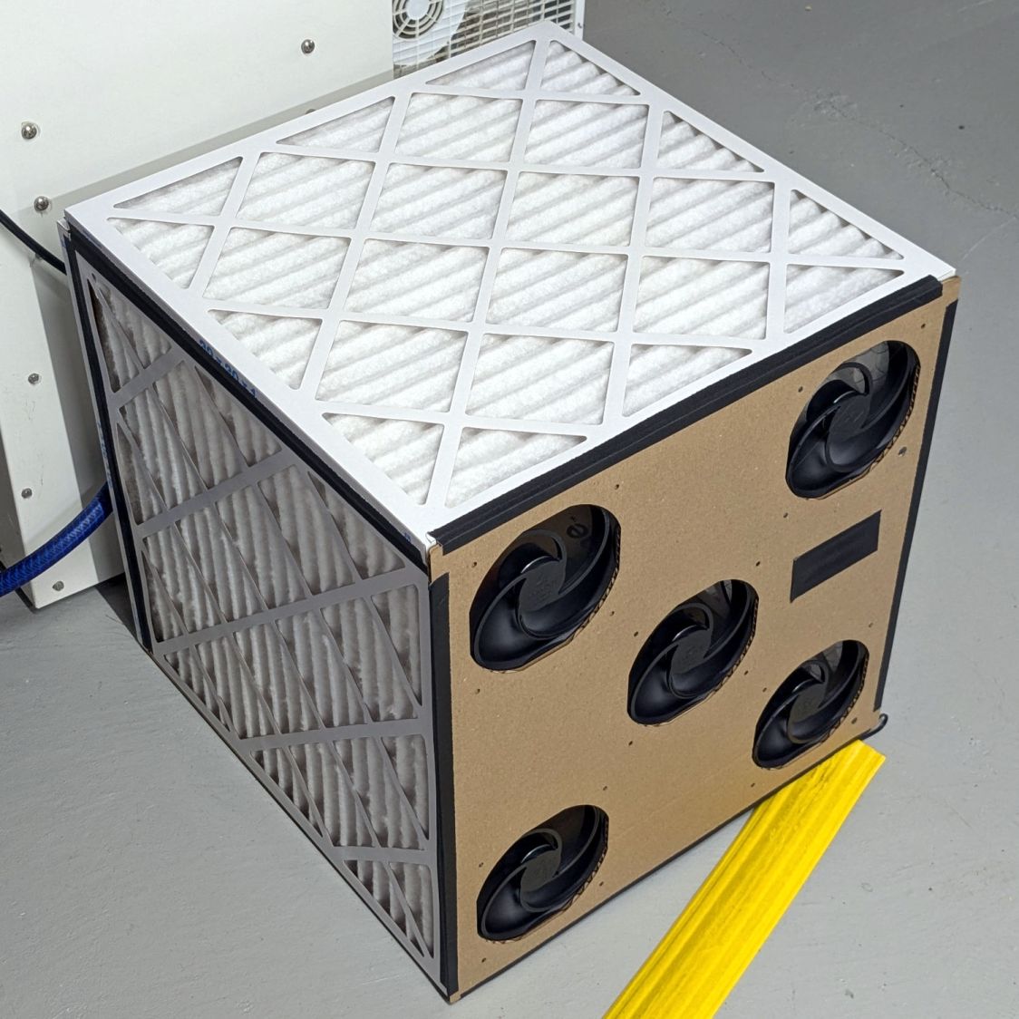
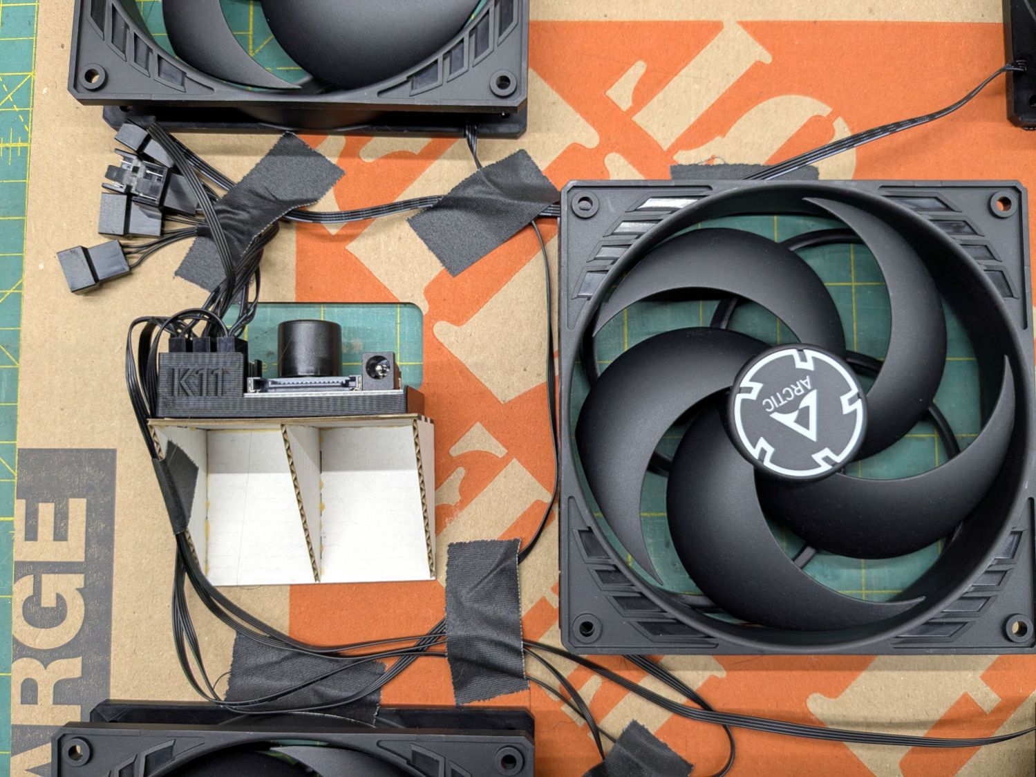
A box of air filters that Came With The House™ (and fit nothing therein) surfaced during a recent heap probe and prompted a quick-n-dirty project:
Basement Air Filter Box – installed
It replaces a tired box fan (barely visible at the top) that’s been shoving air around the basement to equalize the humidity.
The quintet of 140 mm fans seems quieter, although they don’t move quite as much air. Given that I have no way to know how much air circulation is enough, it’s likely sufficient.
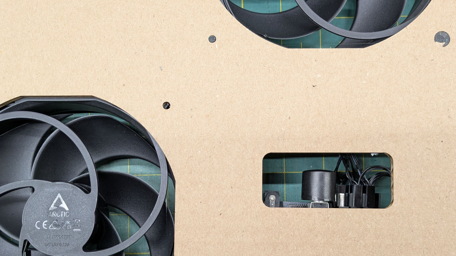
The strip of black tape covers a hole for the knob on the fan power / speed control, although I cranked it up to full throttle and expect to leave it there:
The 3D printed holder came with the controller. I cannot imagine how they have enough time to print a holder for each controller; maybe it’s a QC check for a 3D printer manufacturer.
I intended the controller to sit on the other side of the middle fan, but realized I had to cut the opening after mounting the fans and got the chirality wrong; the wiring in there layout leaves something to be desired.
The fans mount on a sheet of cardboard cut from one side of a Home Depot Extra Large Box and the bottom of the filter box comes from the other side. Because I don’t have a deep emotional attachment to the filters, they’re attached to each other (and the bottom sheet) with hot melt glue. I do have a slight attachment to the fans, but four dabs of glue hold each one in place. More gaffer tape holds the fan sheet to the front of the assembled box, in the unlikely event I must get in there again.
Hey, it’s Christmas: good things come in boxes, right?
The nozzle is 18.5 (-ish) mm above the surface with the laser beam focused to a tight spot. The brass (-ish) tip of the pen flew about 5 mm above the material, requiring considerable attention to the placement of magnets, clamps, and similar accoutrements around the material on the platform.
Having dismantled the pen while replacing its wiring, this seemed like a good time to figure out how to get more clearance under its tip.
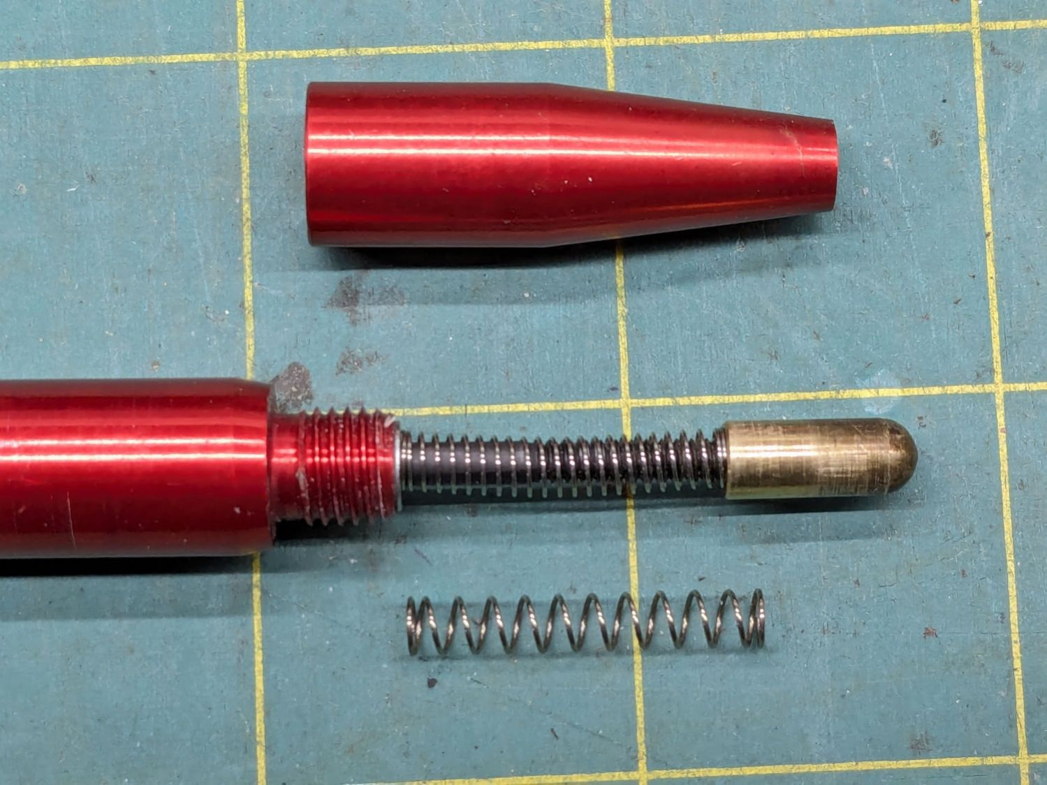
Removing the pen nose shows the tip on its 3 mm screw inside the spring pushing the tip downward:
OMTech focus pen – soft spring – installed
I replaced the original spring (on the bottom) with a softer spring, mostly because the tip exerted what seemed like entirely too much force on the material. That makes no difference for acrylic & plywood, but anything squishier required deploying the focus gauge after I remembered the problem.
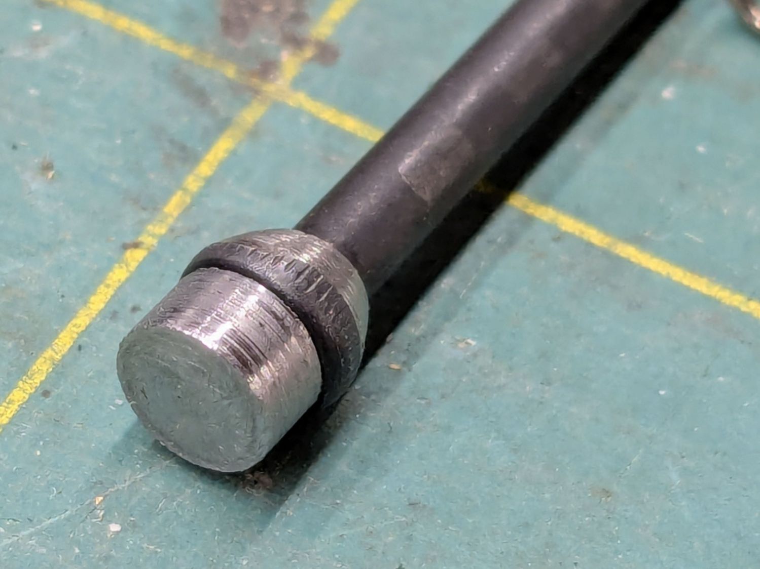
The other end of the screw is impossible to photograph in situ, but the tapered head seats in a recess leaving several millimeters of air below the proximity sensor. I made a little steel slug to reduce the pretravel by filling that gap:
OMTech focus pen – pretravel filler
The spigot on the slug (turned from 7/32 inch steel rod) aligns it with the screw head, with high-viscosity cyanoacrylate adhesive holding it in place:
OMTech focus pen – pretravel filler – installed
The surface finish of my slug matches their tapering, so I figure it’s about right.
A setscrew near the top of the pen clamps the proximity sensor with a few millimeters of adjustment:
OMTech laser focus pen – detail
The slug reduces the pretravel to nearly zero with the sensor at the bottom of its range.
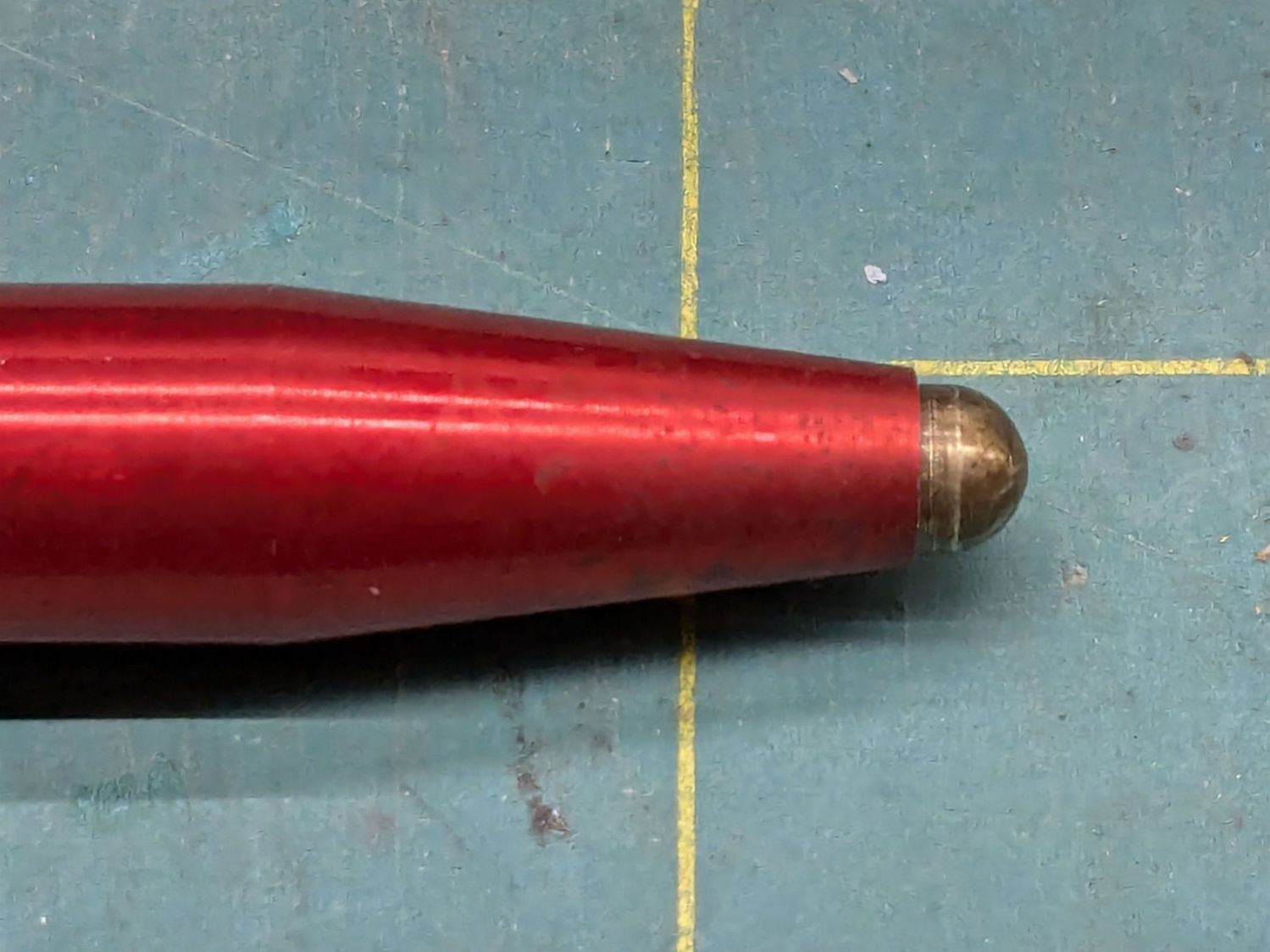
The brass tip had been twisted onto the screw as far as it would go, so I cut a few millimeters off the screw to put the tip closer to the pen nose:
OMTech focus pen – minimal stickout
Even with reduced pretravel, the tip nearly vanished into the pen body before tripping the sensor, so I unscrewed it two turns = 1.4 mm.
With the pen back in the machine and plugged in, measure the switch travel with a step gauge:
OMTech focus pen – revised stickout
Protip: Measure the as-cut height of those steps, then either shim the bottom of the gauge with tape of a suitable thickness or add that much to the layout and cut another set.
With a good step gauge in hand:
Slide it underneath to just touch the tip
Note the measurement = A
Slide it further until the switch trips (red LED on)
Note the measurement = B
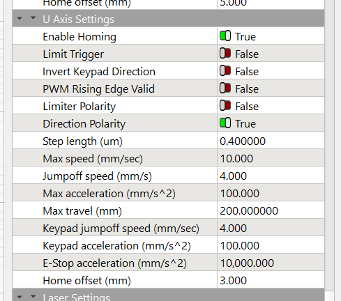
Figure B-A, round up to the next millimeter, then set that value as the Home Offset for whatever axis moves the platform. My tweaked pen had 2.5 mm of travel, so I used 3.0 mm:
Settings – Home Offset
Adjust the pen position to put the tip more than the Home Offsetbelow the nozzle (I picked 5 mm) to ensure the switch will trip before the nozzle contacts the platform, then do an Autofocus.
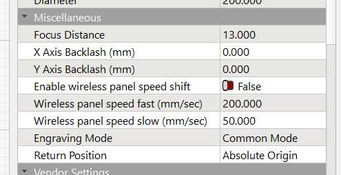
Measure the distance from the nozzle to the platform (mine was 5.5 mm), subtract that from 18.5 mm (the known focused distance for my laser head, as above), and set that as the Focus Distance:
Settings – Focus Distance
Another Autofocus should then put the nozzle exactly 18.5 mm (or whatever your machine needs) off the platform / material.
This shows the pen now flies 5 mm below the nozzle:
OMTech focus pen – normal vs nozzle
The step gauge shows it’s 13.5 mm above the platform, much better than the previous 5 mm.
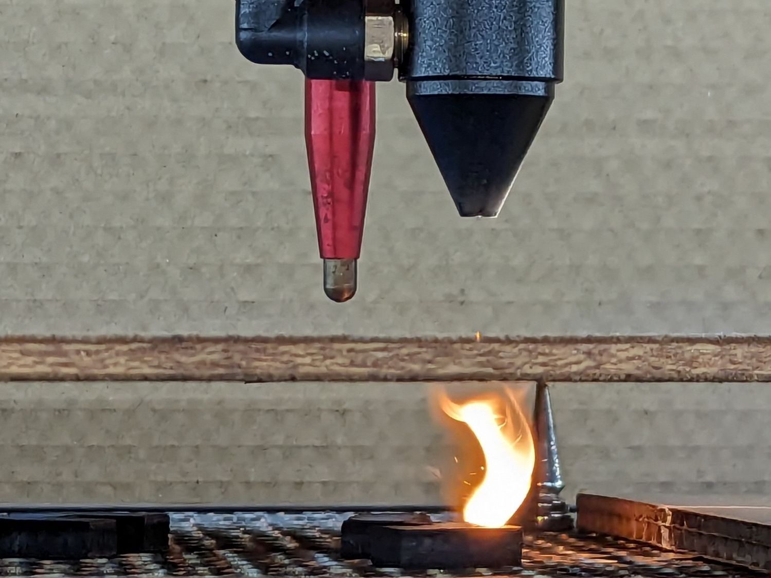
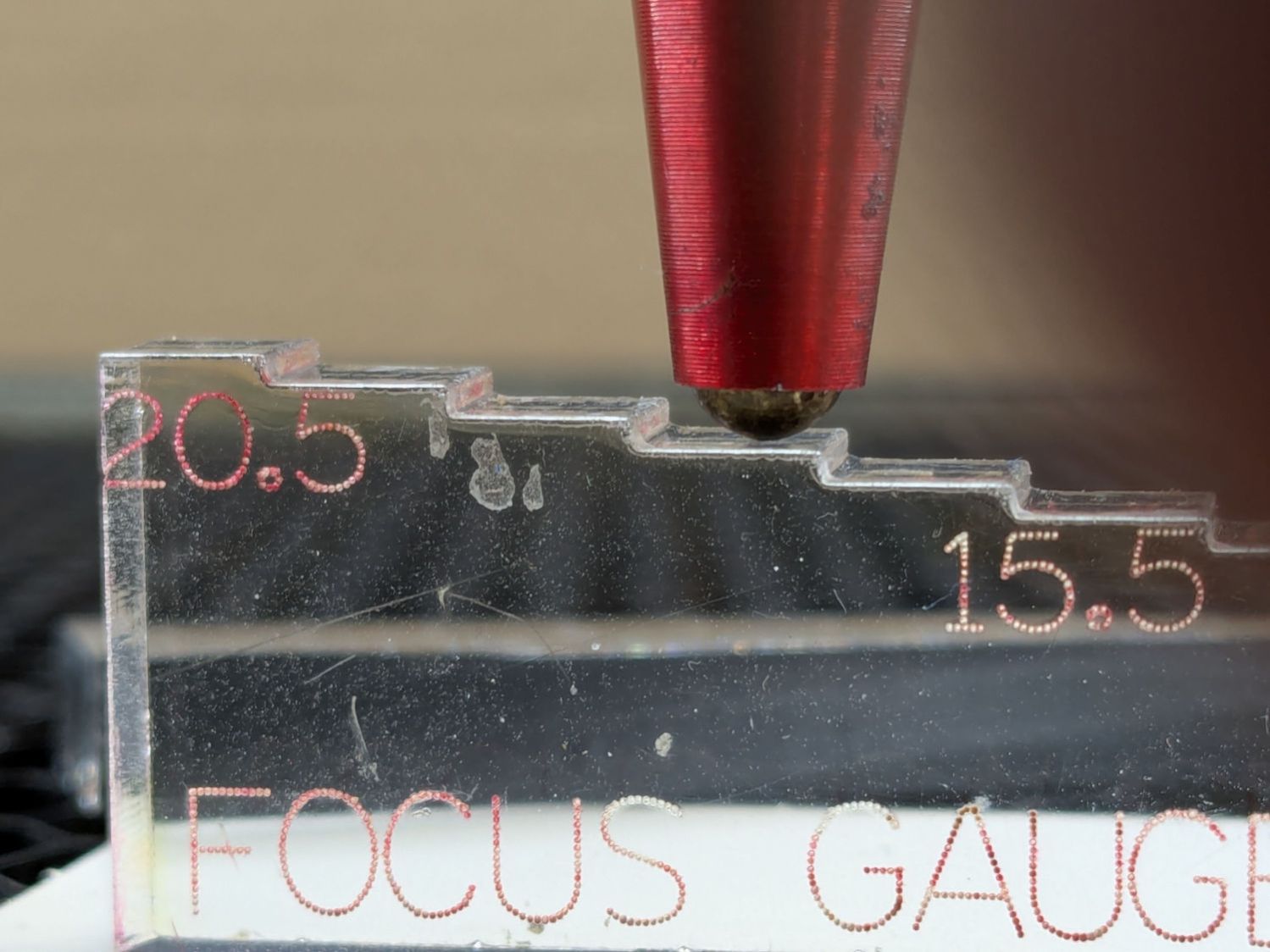
The switch trips juuuust before the nozzle hits the material:
OMTech focus pen – tripped vs nozzle
I should lower the pen a millimeter, but that’s in the nature of fine tuning.
Although the Ortur YRC-1 chuck rotary comes with a long cable, the connector doesn’t match anything in my heap, so an adapter of some sort was in order. The box includes three different adapters for various machines, none of which I have, but which served as raw material.
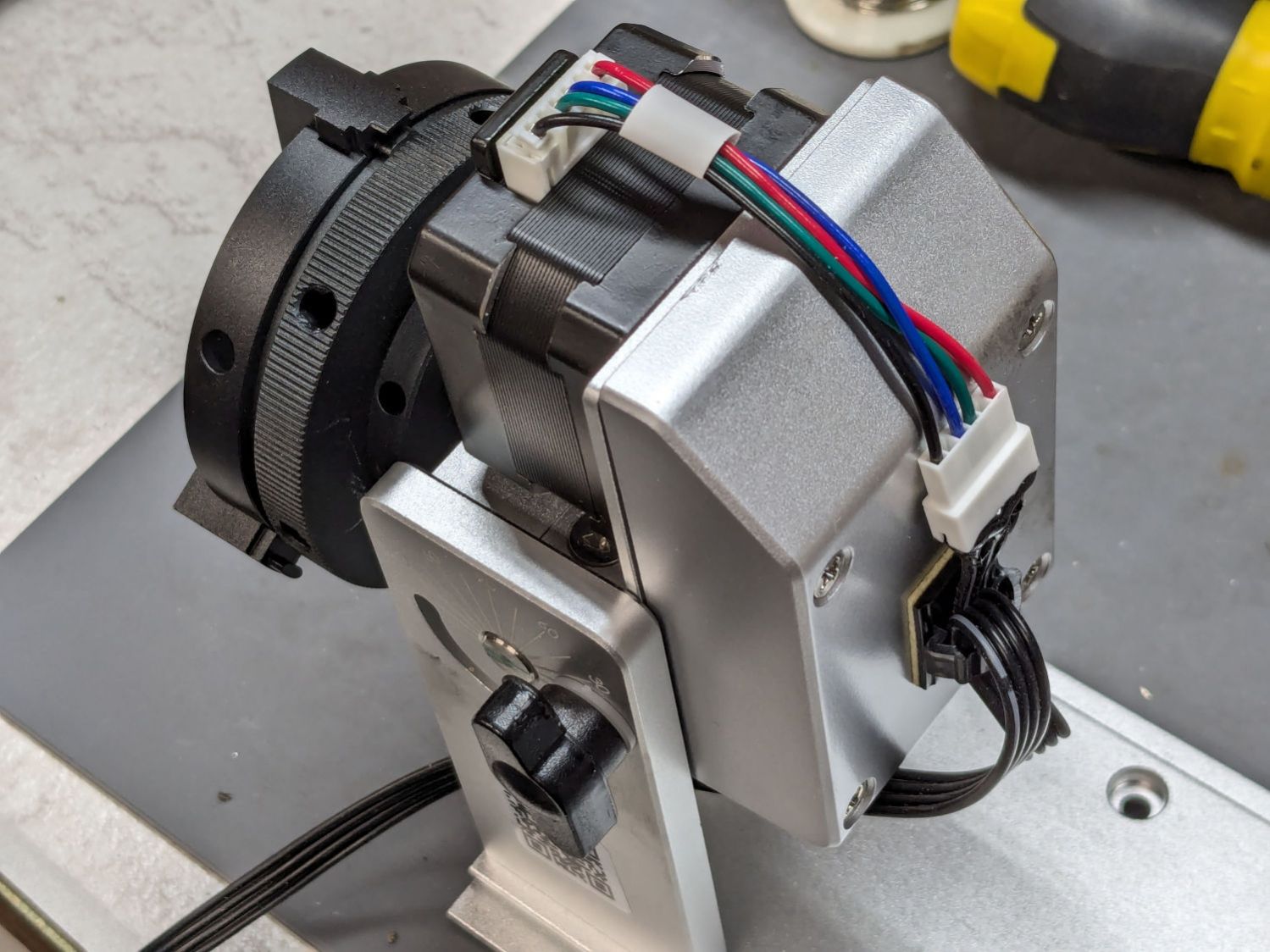
One of the adapters put the motor winding pairs together, which seemed like a Good Idea™:
Ortur Chuck Rotary – cable routing
That view has the stepper motor flipped 180° from its normal orientation; the motor cable connector normally points downward from the bottom.
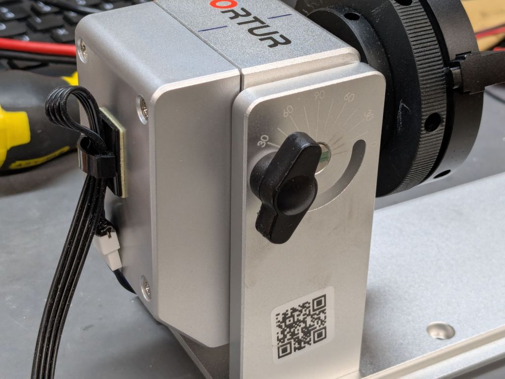
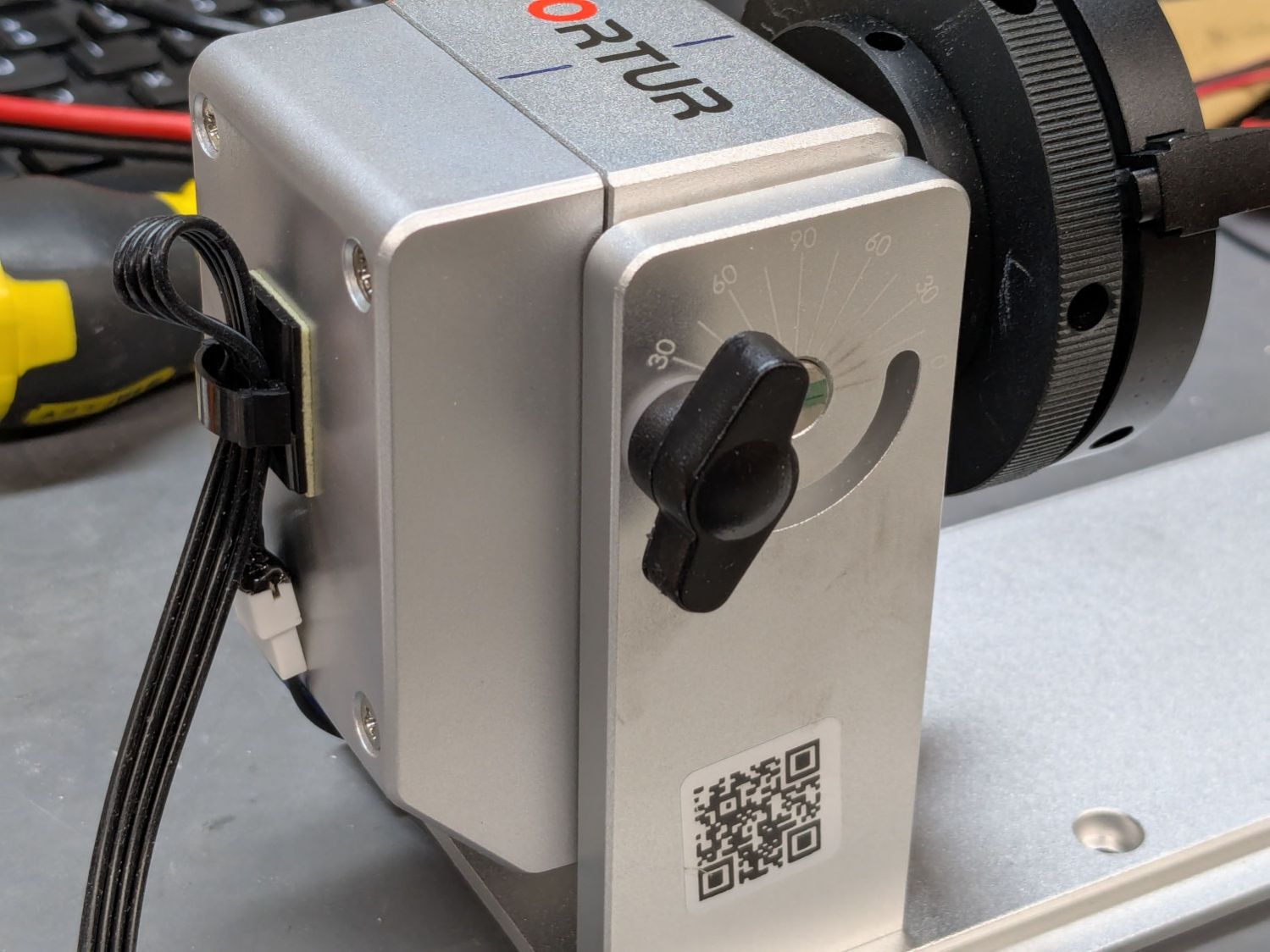
The rotary has no strain relief for the cable, so I stuck a cable clip on its left side (in the normal orientation):
Ortur Chuck Rotary – cable clip
That arrangement captures the adapter, immobilizes the wiring at the motor, and puts all the strain on the more easily replaced cable, which is now a length of flexy 24 AWG silicone ribbon cable.
I don’t have a connector matching the Ortur adapter, but JST SM pins seemed about the right size:
Ortur Chuck Rotary – cable pins
Entombing that mess with a squirt of hot melt glue should keep them out of trouble.
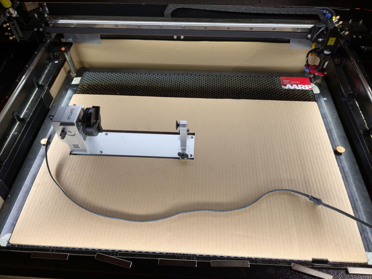
You can see my matching JST SM connectors on the right end of the ribbon cable :
Laser Rotary – on platform
A cable clip stuck to the front cross member of the machine frame (just beyond the angled magnet) holds the unplugged end out of harm’s way when the rotary isn’t present.
Flipping the front-panel switch to enable the rotary driver / disable the Y axis driver enthusiastically spins the chuck when the controller thinks I’m jogging the Y axis:
Laser Rotary – control switch
Making it do something useful requires more pondering.
Having picked up a small rotary intended for Ortur diode laser machines during Black Friday, I knew using it with my OMTech 60 W CO₂ laser wasn’t going to be plug-n-play. The usual connection for a rotary in a CO₂ laser is directly into the stepper motor driver for the Y axis, so the stepper motor in the rotary must handle the same current as the Y axis motor. The OMTech laser has NEMA 23 steppers set for 3.5 A, which would quickly fry the NEMA 17 stepper in the Ortur rotary.
So the general idea was to run the rotary from another stepper driver set for an amp or so. A separate driver would also let me choose microstep settings more suitable for a rotary.
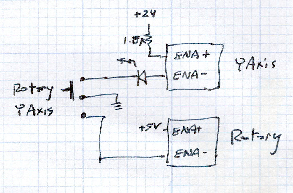
A simple SPDT switch enables the appropriate driver:
Laser Rotary Enable doodle
NB: Leaving the ENA pins of a stepper driver disconnected enables the motor output and passing current through them disables the motor; why that function was not labeled DISABLE remains a mystery.
So the switch looks bassakwards, but it connects the -ENA pin of the disabled driver to GND / common, with its +ENA pin tied to the supply.
Translating that doodle into hardware required drilling holes in what passes for the laser’s front panel:
Laser Rotary – control switch
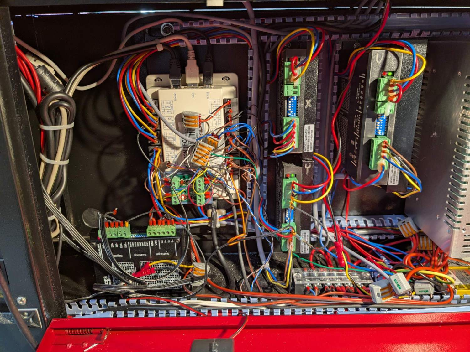
The new driver stands up in bottom of the electronics bay:
Laser Rotary – R driver – detail
The loose wire over on the left is a remnant of the discovery that the KT332N controller’s General output bits do not behave as expected. While you (well, I) can set their state through the display’s MENU → DIAGNOSES screen, the controller unilaterally slams them low = active while running a job. To be fair, the manual does say “General output, reserved”, but I had to find out the hard way.
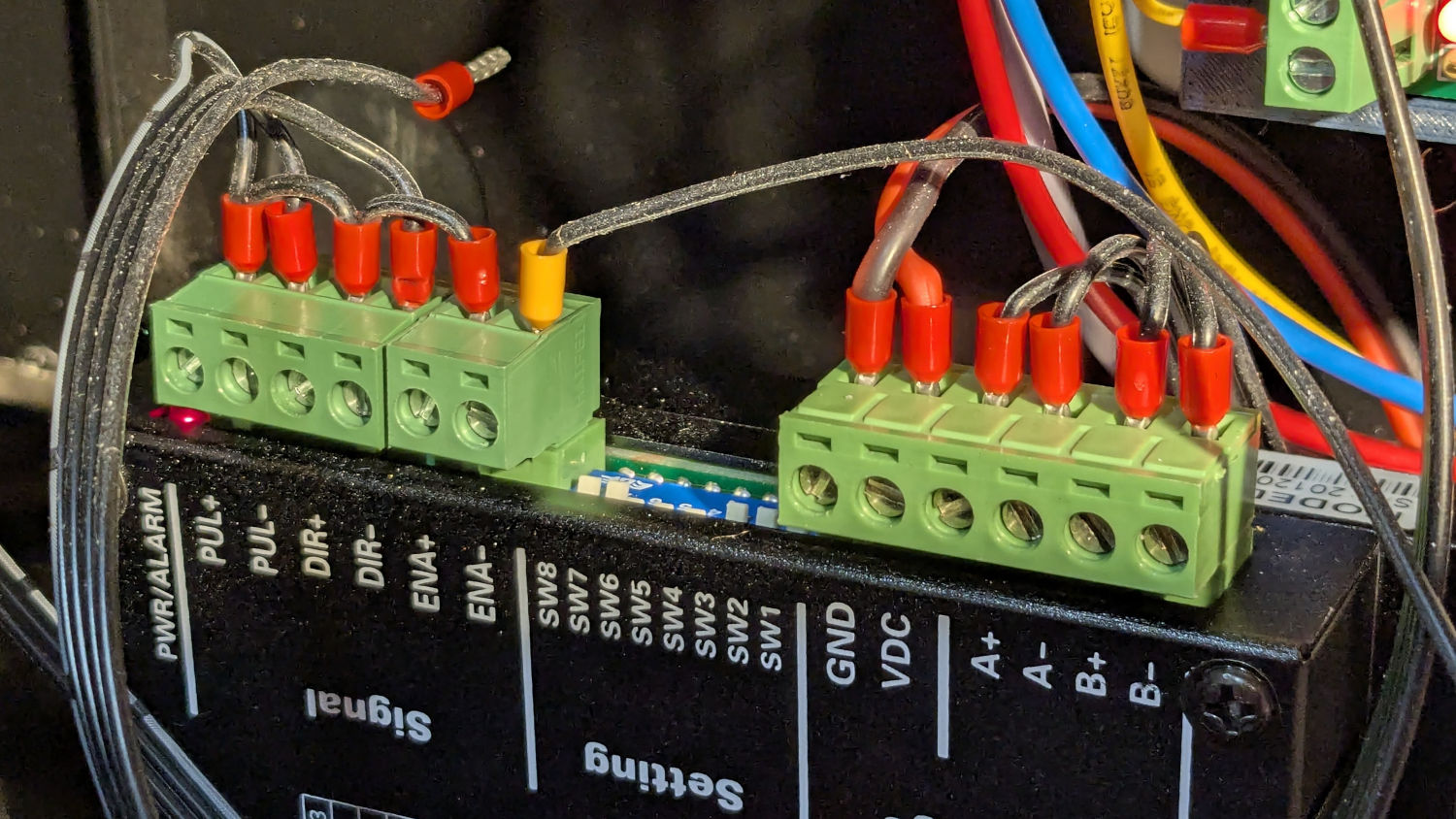
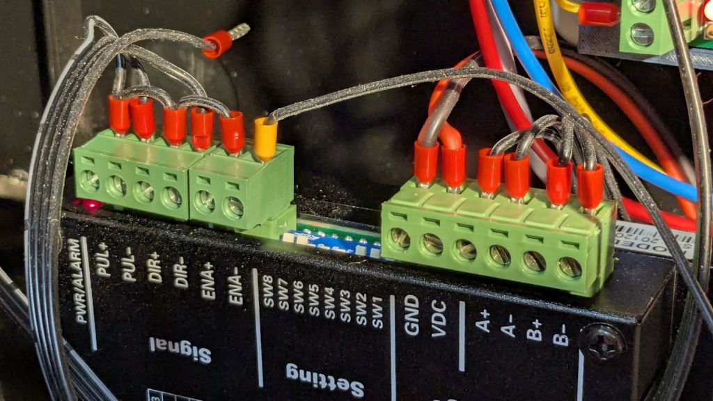
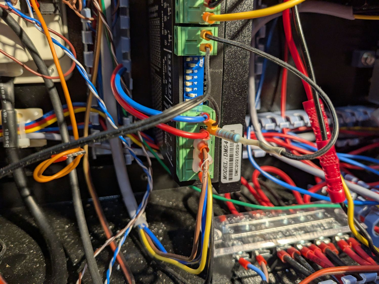
The +ENA terminal comes from the +5V supply, along with the other + terminals. The -ENA terminal goes off to the switch, along with two wires from the existing Y axis stepper driver:
Laser Rotary – Y driver wiring
The 1.8 kΩ resistor sticks out of a ferrule doubled up in the 24V terminal feeding the driver and connects to a wire into the +ENA terminal. Two wires from the switch connect to the -ENA and GND terminals, join the -ENA wire from the rotary driver, and crawl through the machine to the front panel.
The new power supply on the far right completes the electronics bay installation:
Laser Rotary – electronics bay
Obviously, the wiring situation is completely out of control.
Up top, though, it looks like it grew there:
Laser Rotary – on platform
Now, to figure out the settings …
Edit: The rotary has a pulley ratio of 1:3, so the step/rev value is three times the DIP switch setting on the stepper driver. For this setup, 1600 → 4800 step/rev.