Ed Nisley's Blog: Shop notes, electronics, firmware, machinery, 3D printing, laser cuttery, and curiosities. Contents: 100% human thinking, 0% AI slop.
Even after printing nice calibration objects, real-world projects sometimes don’t come out quite right.
This set of fairing plates for my Esteemed Wife’s bike was a test case to see if the hole threads would stick together better than before. As it turned out, no, they didn’t:
Upper mount – hole separation
The Infill w/t=1.75 setting seems to be slightly too high (meaning Skeinforge thinks the threads occupy slightly more space than they actually do), so the top isn’t quite as nicely packed as it should be.
The threads around the holes aren’t sticking together at all. A closer look:
Hole details
The first layer of the upper-left and lower-right holes didn’t adhere to the ABS covering the aluminum plate and tangled with the remaining layers. In various combinations: the perimeter didn’t bond to the extra shells, those shells didn’t bond together, and the fill didn’t bond to the shells.
Parameters:
Infill overlap = 0.3
Infill solidity = 0.25
Infill w/t = 1.75
Feed = 40 mm/s
I could dial back the perimeter feed ratio a bit, but that won’t affect the infill-to-shell problem. Adhesion to the build plate depends critically on the initial height of the first layer and the speed of the nozzle across the plate; those I can adjust.
Another mechanical cause: slightly loose drive belts. That usually shows up as backlash causing oval circles, but for small circles a pair of loose belts might just produce a too-small circle. I’m about to take the whole XY stage apart for another purpose, so adjusting the belts will come naturally.
Those plates handle the upper mount points, but the fairing also attaches to each side of the front fork. A nice rounded oval mates the fairing to the bracket, with two foam pads adapting the flat plates to the curved fairing surface. This view shows the outside of the fairing:
Lower mount – front
The hole position requires a mirror-image pair of mounts that, mercifully, all fit on the build platform at once. The solid models look about like you’d expect:
Lower Bushings
Those little tabs on the inside edge of the bracket recess printed about as poorly as you’d expect, but they’re not really critical.
I printed a set of white plates for my bike, installed the new filament tensioner, and went full frontal Barbie for my favorite ladies. This view shows the inside of the fairing:
Lower mount – rear
Turns out my ladies don’t like pink any more than I do.
The OpenSCAD source:
// Clamp plates for Zzipper fairing on Tour Easy recumbents
// Ed Nisley - KE4ZNU - Mar 2011

// Build with...
//	extrusion parameters matching the values below
//	4 outer shells
//	4 solid surfaces at top + bottom

include </home/ed/Thing-O-Matic/lib/MCAD/units.scad>

// Extrusion parameters for successful building

ThreadWidth = 0.55;					// should match extrusion width
ThreadZ = 0.33;						// should match extrusion thickness

HoleWindage = ThreadWidth;			// enlarge hole dia by extrusion width

// Plate dimensions

Layer1X = 35;						// against fairing surface
Layer1Y = 30;
Layer1Z = 2*ThreadZ;

HoleOffsetX = 5.0;					// will be sign-flipped as needed
HoleOffsetY = -(Layer1Y/2 - 10.0);

Layer2Margin = 1.5;					// uncovered edge
Layer2X = Layer1X - 2*Layer2Margin;
Layer2Y = Layer1Y - 2*Layer2Margin;
Layer2Z = 3*ThreadZ;

MountX = 16.3 + HoleWindage;		// front fork mounting plate
MountHoleOffset = 13.0;				// Y end to hole center
MountY = Layer1Y;
MountZ = 4*ThreadZ;					// recess depth
MountCap = 3.0;						// endcap arc height
MountR = (pow(MountCap,2) + 0.25*pow(MountX,2)) / (2*MountCap);	// ... radius

Layer3Margin = 1.5;
Layer3X = Layer2X - 2*Layer3Margin;
Layer3Y = Layer2Y - 2*Layer3Margin;
Layer3Z = 3*ThreadZ;

PlateZ = Layer1Z + Layer2Z + Layer3Z;

HoleDia = 0.25 * inch;				// these are 1/4-20 bolt holes

// Convenience settings

BuildOffsetX = 3.0 + Layer1X/2;		// build X spacing between top & bottom plates
BuildOffsetY = 3.0 + Layer1Y/2;		//	... Y

Protrusion = 0.1;					// extend holes beyond surfaces for visibility

//---------------
// Create plate

module Plate() {

  union() {
	  translate([0,0,Layer1Z/2])
		scale([Layer1X,Layer1Y,1]) cylinder(r=0.5,h=Layer1Z,$fn=32,center=true);
	  translate([0,0,Layer1Z + Layer2Z/2])
		  scale([Layer2X,Layer2Y,1]) cylinder(r=0.5,h=Layer2Z,$fn=32,center=true);
	  translate([0,0,Layer1Z + Layer2Z + Layer3Z/2])
		  scale([Layer3X,Layer3Y,1]) cylinder(r=0.5,h=Layer3Z,$fn=32,center=true);
  }

}

//---------------
// Create hole

module Hole(OffsetX,OffsetY) {

  translate([OffsetX,OffsetY,PlateZ/2])
	cylinder(r=(HoleDia + HoleWindage)/2,
			h=(PlateZ + 2*Protrusion),
			center=true,$fn=10);

}

//---------------
//-- Build the things...

// Right side

translate([BuildOffsetX,BuildOffsetY,0])
  difference() {
	Plate();
	Hole(HoleOffsetX,HoleOffsetY);
  }

translate([BuildOffsetX,-BuildOffsetY,0])
  difference() {
	  Plate();
	  Hole(-HoleOffsetX,HoleOffsetY);
	  translate([-HoleOffsetX,(HoleOffsetY - MountY/2 + MountHoleOffset),(PlateZ - MountZ/2 + Protrusion/2)])
		intersection() {
		  cube([MountX,MountY,(MountZ + Protrusion)],center=true);
		  translate([0,(MountY/2 - MountR),0]) cylinder(r=MountR,h=(MountZ + Protrusion),center=true);
		}
  }

// Left side

translate([-BuildOffsetX,BuildOffsetY,0])
  difference() {
	Plate();
	Hole(-HoleOffsetX,HoleOffsetY);
  }

translate([-BuildOffsetX,-BuildOffsetY,0])
  difference() {
	  Plate();
	  Hole(HoleOffsetX,HoleOffsetY);
	  translate([HoleOffsetX,(HoleOffsetY - MountY/2 + MountHoleOffset),(PlateZ - MountZ/2 + Protrusion/2)])
		intersection() {
		  cube([MountX,MountY,(MountZ + Protrusion)],center=true);
		  translate([0,(MountY/2 - MountR),0]) cylinder(r=MountR,h=(MountZ + Protrusion),center=true);
		}
  }
After a few ranging shots, I printed coasterman’s calibration set. Much to my surprise, they came out very nicely… after the obligatory bit of tuning.
Everything printed at 40 mm/s, 0.33 mm layer thickness, 220 °C first layer / 210 °C all other layers, 120 °C aluminum platform. The first layer prints at 25% of normal speed/feed atop an aluminum plate covered with a thin layer of ABS. I’m still tweaking temperatures, first layer speeds, and ABS thickness on the plate.
All the pix have been contrast-stretched and lightly sharpened to bring out the detail. You’re going to start seeing a lot of Barbie style objects, because I want to use up that pink filament, OK?
The single-wall open box has an actual filament width of 0.55 mm, suggesting a w/t of 1.7. The Cool plugin throttled the speed down to 15 sec/layer and it’s just about perfect.
I simply didn’t believe the 50 mm tower would print until I saw it emerge intact. This is with 2 extra shells and 25% fill, at 15 sec/layer. The suck-in along the right edge comes from laying down the perimeter shell before doing the fill: that’s where the nozzle departs inward after finishing the perimeter. The distance to the fill was less than the Reversal threshold, so the stepper extruder didn’t reverse.
A few passes with the perimeter width/thickness tester resulted in a block that fits into the slot all eight ways with w/t=1.75 (with some orientations, mmm, much tighter than others, I’ll admit). The fill w/t=1.5 is obviously too low, because the top layer got overcrowded even with 25% fill on the internal layers.
The suck-out at the left corner shows where Reversal starts inhaling filament on alternate layers. This was with 35 rpm and 100 ms, which seems too aggressive. It’s not bad-looking, mind you; I touched up the sides of the block with a bit of sandpaper to smooth out the tallest ridges.
Calibration – Perimeter Width
The second classic 20 mm solid box looked good at w/t=1.75 and fill w/t=1.65, apart from the corner that pulled off the ABS and grew a tab that messed up half the layers. That’s what caused me to junk the ABP; about which, more later. The first one came out with the top looking a bit thin at fill w/t = 1.75.
Calibration – 20 mm solid box
The first hollow box just didn’t work at all, because setting w/t=1.75 built a single shell wall and the overhung top didn’t connect to the walls.
Calibration – 20 mm hollow box – failure
Changing to w/t=1.5 produced a reasonably good result, although the lid didn’t quite attach to the walls across the long diagonal. I always drop a scrap ball bearing inside to prove it’s hollow in there.
Calibration – 20 mm hollow box – success
The Oozebane tests looked great, even though I’m not using Oozebane: a stepper extruder pretty much eliminates the need for that plugin. The front one had a few strings at 85 ms / 75 ms, the back one was clean at 100 / 75, but the fill got strangely thin.
Calibration – Oozebane test
Skeinforge 39 handles bridge layers oddly: no extra shells, fill parallel to one axis, and I really didn’t have it set up right. The holes look OK, albeit with poor contact with the fill.
Calibration – Precision – top
The aggressive overhang didn’t work at all, but the 45 degree slope looks passable if you’re not too fussy. Small overhangs may be OK, but you really can’t do them without support material underneath.
Calibration – Precision – bottom
All in all, the combination of a stepper extruder, spring-loaded filament tensioner, and an ABS-coated aluminum platform seems to produce good results. Maybe I can finally start printing useful objects…
However, as we all know, cranking out good calibration cubes doesn’t guarantee anything else will print the same way…
Putting a geared stepper motor on the MK5 filament drive produced greatly improved print quality, which meant I could finally print ScribbleJ’s version of the classic Wade Filament Tensioner and expect that it’d come out right. It’s a rather large lump of plastic that printed quite nicely on an aluminum plate.
Wade-ScribbleJ Filament Tensioner on plate
The whole thing looks like this when it’s all assembled and adjusted:
Complete Geared Stepper Extruder
[Update: The motor comes directly from the usual eBay supplier. You won’t find another one like it, but this is directly from the label…
38 mm case
Minebea-Matsushita 17PM-K150-P1V
No. T6824-02
]
You can see the two thermal switches near the bottom of the picture. The 100 °C switch is inside the acrylic frame on the Thermal Riser, the 40 °C switch is just taped to the filament tensioner’s base. The former is OK, the latter isn’t as secure as it should be. FWIW, Riser temperatures run around 70 °C during normal extrusion, albeit in a chilly Basement Laboratory without covers on the TOM’s windows.
A better view of the shaft bearings and filament position:
Filament tensioner – overview
The four long screws are 1.5 inch 4-40 from my heap, although 2 inch screws would give more room for adjustment. Some folks mount the screws the other way around, with the nuts pressing on the springs and little knobs on the nuts. I gave up on the washers to get a bit more adjustment range.
The springs came from my Big Box o’ Little Springs, sporting absolutely no pedigree at all. They’re not quite completely compressed, so there’s a bit of push left in them to handle filament diameter variations (which is the whole point of this exercise). I added four nuts (between the shaft bearing plate and the idler block) to keep the idler block from resting against the drive gear when there’s no filament in place: inserting a new filament became much easier.
Somewhat to my surprise, the entire filament drive gear assembly is free-floating and self-aligning within the housing:
Filament drive gear detail
I enabled the option to put a 5 mm diameter cleanout hole in the bearing housing, which turned out to be absolutely essential for monitoring the location of the drive gear inside all the machinery. You can barely see the hole in the first picture, on the left side of the curved section.
A floating shaft means the 7-tooth motor drive gear’s position must line up with wherever the 51-tooth filament drive gear happens to be. There’s not much room to adjust the motor gear, but a few iterations sorted out the proper number and placement of all the filament drive shaft washers, nuts, and bearings.
Filament drive gear – shaft spacing
You (well, I) really really must put a flat on the shaft and use full-strength Loctite to hold the setscrew in place. I used an all-thread M6x40 bolt because that’s what I had on hand, but a partially threaded M6x50 bolt would provide better support for the bearings, more clearance for the spacers, and look a lot better; it’d require a custom-turned bushing instead of the nut against the big gear, though.
Flatted filament drive shaft
I initially used low-strength Loctite. Word: a loose drive gear setscrew can convince you that Skeinforge’s Reversal plugin isn’t working after you make many changes with worsening results. Those fast reversals loosen the setscrew in short order.
The diameters of the 7- and 51-tooth herringbone gears determine the center-to-center distance between the motor shaft and the extruder shaft. Alas, two of the motor mounting bolts wind up directly behind the larger gear. I marked the gear adjacent to the bolt heads and drilled a hole that just barely admits the hex wrench:
Stepper Extruder – motor mount access hole
If you knew where that hole was supposed to be, you could print it right into the gear, but I haven’t a clue as to how you might algorithmically determine the precise location on the as-printed gears.
The modified OpenSCAD source produces two recesses for the bolt head and nut, but I just applied an end mill to the head side of the finished idler block. There’s no room for the bolt head between the block and the motor mounting plate.
Idler housing with recessed bolt
Of course, I modified the OpenSCAD code along the way:
Changing the bearing size moved the base: use front_bearing_r in the routine that punches the holes
Add a complete outer surface on the idler block; I thought I might want a flat metal plate to distribute the stress.
Add bolt head / nut recesses for idler block pulley shaft
Include base_wall_h in the calculation for idler_max_h
Tweaked spacing to get idler bolt heads out of the walls
Extend motor wall rightward to cover all of the base plate
Adjust base hole positioning: -10 / +4.0, not -10 / +3.5
But not all instances of 3.5 must change, I think
Filament offset may need further tweakage
Other miscellaneous tweaks
Not all of those changes made it to the printed object shown here; if I ever print another one, they’ll be included. Use at your own risk!
The OpenSCAD source, which is almost entirely ScribbleJ’s work:
//  MK5 Wade's-Style Tensioner
// (C)2011, Christopher "ScribbleJ" Jansen
//
// Released under the BSD license.

// Modifications: Ed Nisley - KE4ZNU - Mar 2011

// Parametric Settings

// INTERESTING OPTIONS
// 1 = on, 0 = off
extend_shaft = 1 ;		// 0 will allow a bridge over the front of the motor hole
make_stepper_holes = 1;	// 1 will create mounting holes for a stepper mount.
make_dc_holes = 0;		// 1 will create mounting holes for a MK5 DC motor.
motor_shaft_supports = 1;	// 1 will create angle supports to the motor shaft. (See options below for support angle/size)
generate_for_viewing  = 0;	// 1 creates the model suitable for viewing.  0 creates the model suitable for printing.

cleaning_hole_d = 5;		// The diameter of a cleaning hole to punch.  (0 = no cleaning hole)
cleaning_hole_r = cleaning_hole_d/2;
cleaning_hole_angle = 75;	// Angle offset from 9 o'clock position (i.e. directly left)

hole_protrusion = 0.05;	// surface clearance for holes and suchlike

hole_windage = 0.4;			// allowance for small hole shrinkage

// _r = radius, _d = diameter, _h = height

// REAR BEARING = bearing closest to motor
rear_bearing_d = 17.0 + hole_windage;
rear_bearing_r = rear_bearing_d/2;
rear_bearing_h = 6.0;

// EXTRA SHAFT = include an extra length of motor shaft.  This is useful
// for giving your idler bolts enough room depth-wise.
extra_shaft = 5;

// FRONT BEARING = bearing furthest from motor  (Technically, front bearing diameter must be >= than rear to print properly... so
// there are many places in the code that we assume the front bearing is the largest d.
front_bearing_d = 17.0 + hole_windage;
front_bearing_r  = front_bearing_d/2;
front_bearing_h = 6;

// EXTRA FILAMENT = extend the length of the filament column.  This is useful
// for giving your idler bolts enough room height-wise.
extra_filament = 40;

filament_margin = 3.0;	// How wide is shaft on either side of filament?
filament_d = 4;			// How wide is filament shaft hole?
filament_r = filament_d/2;

// FILAMENT OFFSET = How far from the center of the motor axis your MK5 plastic pusher gear thingy
// or hobbed bolt groove is.
filament_offset = 6;

// MOTOR WALL = "rear" wall of tensioner.
motor_wall_h = 5;  		// thickness of wall
motor_bolt_d = 3.0 + hole_windage;		// diameter of motor mounting bolts
motor_bolt_r  = motor_bolt_d/2;
motor_bolt_h = motor_wall_h;
motor_bolt_hex_d = 6.3 + hole_windage;	// diameter of motor mounting bolt hex caps
motor_bolt_hex_r  = motor_bolt_hex_d/2;
motor_bolt_hex_h = 3;			// height of hex caps
motor_dropbolts   = 2.0;		// distance to sink bolts into wall
motor_boltmargin = 5;			// Distance to allow between bolts and edges of wall.
motor_shaft_width = 5;			// How thick is the wall around the motor shaft?
motor_shaft_support_width = 10;	// How thick are the motor supports (if any)?
motor_shaft_support_angle = 0;	// if non-0, will create three supports spaced apart this many degrees.
								// 0 creates a single support if enabled above.

// 31 is distance from center to bolt holes... do not chang this without changing hardcoded numbers
// in the motor bolt generating module.
motor_wall_w = 31 + (motor_boltmargin * 2) + motor_bolt_d;
motor_wall_d = 31 + (motor_boltmargin * 2) + motor_bolt_d;

// IDLER BEARING = the bearing that holds the plastic against the hobbed bolt/MK5 plastic pusher.
// You should include about an extra 2mm over your actual bearing measurements here so it can spin freely.
idler_bearing_d = 19 + 3;
idler_bearing_r  = idler_bearing_d/2;
idler_bearing_h = 6 + 2;
h_i = idler_bearing_h/2;
idler_bearing_bolt_d = 5;	// This is the size of the bolt holding the bearing in place.
idler_bearing_bolt_r = idler_bearing_bolt_d/2;

idler_bolt_d = 3.0 + hole_windage;		// This is the size of the (4) bolts holding the idler block in place.
idler_bolt_r  = idler_bolt_d/2;
idler_bolt_margin = 4;	// How much room to allow between bolt holes and edge of block.
idler_bolt_hex_d = 7.0 + hole_windage;
idler_bolt_hex_r  = idler_bolt_hex_d/2;
idler_bolt_hex_h = 5;         // Arbitrarily large to be sure to punch through supports/shaft.
idler_dropbolts   = 2.0;           // Try negative numbers here to catch your nuts on the supports.

idler_wall = 2.5;			// thickness of wall to left of idler bearing

idler_recess_dia = 9.0 + hole_windage;		// recess idler shaft bolt head & nut
idler_recess_r = idler_recess_dia/2;
idler_recess_depth = 3.0;

// BASE = the bottom part that bolts onto the hot end.
base_wall_h = 6;		// How thick or tall is the base.
base_h=base_wall_h;
base_bolt_d  = 3.0 + hole_windage;		// Size of bolts used to hold base -- rest of base settings are same as motor wall settings above.
base_bolt_r   = base_bolt_d/2;
base_bolt_hex_d = 6.3 + hole_windage;
base_bolt_hex_r  = base_bolt_hex_d/2;
base_bolt_hex_h = 5;
base_dropbolts = 1.5;
base_boltmargin = 6;
base_filament_offset_x = 6;

// 30/14.0 is distance from center to bolt holes...
// do not change this without changing hardcoded numbers
//  in the base bolt generating module.
base_w = 30 + (base_boltmargin*2) + base_bolt_r;
base_d  = 14.0 + (base_boltmargin*2) + base_bolt_r;

// base_z_extra is used for configurations where base wall or motor wall
//  would be unprintable due to differential in height.
// shrinks or grows the base to fit.
base_z_extra = ((idler_bearing_h/2) + rear_bearing_h + motor_wall_h) - ((base_d/2) + 3.5);
base_filament_offset_z = -3.5;  // How far the filament hole is from the bolts furthest from the motor.
base_d_use = base_d + base_z_extra;

// make up difference between bottom of wall and base... not really necessary but more support more better.
motor_wall_extra = front_bearing_r + (extra_filament/2) + base_h - (motor_wall_d/2);

// Calculate maximum space for idler block.
idler_max_h = idler_bearing_d + extra_filament + ((-base_bolt_hex_h+base_dropbolts)*2) - base_wall_h;
half_idler_max_h = idler_max_h/2;
idler_bolt_y = half_idler_max_h - idler_bolt_r - idler_bolt_margin;

//idler_max_w = .55 * idler_bearing_d;
idler_max_w = idler_bearing_r + idler_wall;			// enforce wall thickness on right side

idler_max_d = extra_shaft+front_bearing_h+idler_bearing_h+rear_bearing_h+((-motor_bolt_hex_h+motor_dropbolts)*2);
half_idler_max_d = idler_max_d/2;
idler_bolt_z = half_idler_max_d - idler_bolt_r - idler_bolt_margin;

echo(str("Idler block size: ",idler_max_d," x ",idler_max_h," x ",idler_max_w));
echo(str("Idler bolt spacing: ",2*idler_bolt_z," x ",2*idler_bolt_y));

// This module generates the bolt pattern for the idler, trying to fill the maximum space available.
module IDLERBOLTS()
{
	// echo(idler_bolt_r, idler_bolt_d, idler_max_d, idler_bolt_z, half_idler_max_d);
	// echo(idler_bolt_r, idler_bolt_d, idler_max_h, idler_bolt_y, half_idler_max_h);

	translate([idler_bolt_z,idler_bolt_y,0]) cylinder(r=idler_bolt_r, h=40);
	translate([idler_bolt_z,-idler_bolt_y,0]) cylinder(r=idler_bolt_r, h=40);
	translate([-idler_bolt_z,idler_bolt_y,0]) cylinder(r=idler_bolt_r, h=40);
	translate([-idler_bolt_z,-idler_bolt_y,0]) cylinder(r=idler_bolt_r, h=40);

	translate([0,0,-idler_bolt_hex_h])
	{
		translate([idler_bolt_z,idler_bolt_y,0]) cylinder(r=idler_bolt_hex_r, h=idler_bolt_hex_h,$fn=6);
		translate([idler_bolt_z,-idler_bolt_y,0]) cylinder(r=idler_bolt_hex_r, h=idler_bolt_hex_h,$fn=6);
		translate([-idler_bolt_z,idler_bolt_y,0]) cylinder(r=idler_bolt_hex_r, h=idler_bolt_hex_h,$fn=6);
		translate([-idler_bolt_z,-idler_bolt_y,0]) cylinder(r=idler_bolt_hex_r, h=idler_bolt_hex_h,$fn=6);
	}

}

// This module generates an idler block, filling the maximum space available.
module IDLER()
{
	difference()
	{
		translate([0,0,(idler_max_w/2)-(.25 * idler_bearing_bolt_d)]) cube([idler_max_d, idler_max_h, idler_max_w], center=true);
		translate([0,0,(-.5 * idler_bearing_bolt_r) + idler_max_w]) rotate([0,180,0]) IDLERBOLTS();
		#rotate([0,90,0]) cylinder(h=idler_max_d+1, r=idler_bearing_bolt_r,center=true);
		#rotate([0,90,0]) cylinder(h=idler_bearing_h, r=idler_bearing_r, center=true);
		translate([(idler_max_d/2 - idler_recess_depth),0,0])
		  rotate([0,90,0])
		  #cylinder(r=idler_recess_r,h=(idler_recess_depth + hole_protrusion),$fn=10);
		translate([(-idler_max_d/2 + idler_recess_depth),0,0])
		  rotate([0,270,0])
		  #cylinder(r=idler_recess_r,h=(idler_recess_depth + hole_protrusion),$fn=10);
	}
	echo(str("IDLER BEARING BOLT LENGTH REQUIRED (longer is OK): ", idler_max_d, "mm"));
}

// This module creates the motor shaft hole pattern.
module MOTORSHAFT()
{
	// idler bearing
	cylinder(h=idler_bearing_h, r=rear_bearing_r, center=true);
	// front bearing
	translate([0,0,h_i]) cylinder(h=front_bearing_h, r=front_bearing_r);
	if(extend_shaft == 1)
	{
		translate([0,0,h_i]) cylinder(h=front_bearing_h+(extra_shaft/2)+50, r=front_bearing_r);
	}
	// rear bearing
	translate([0,0,0 - h_i - rear_bearing_h - (extra_shaft/2) - motor_wall_h])
		cylinder(h=         rear_bearing_h + (extra_shaft/2) + motor_wall_h, r=rear_bearing_r);

	echo(str("MOTOR SHAFT/BOLT LENGTH REQUIRED (longer is OK): ", front_bearing_h+idler_bearing_h+rear_bearing_h+motor_wall_h+(extra_shaft/2), "mm"));
	echo(str("MOTOR SHAFT LENGTH FROM REAR OF MOUNT TO FILAMENT:", motor_wall_h+(extra_shaft/2)+rear_bearing_h+(idler_bearing_h/2), "mm"));
}

// This module creates an MK5 mount motor hole pattern with optional hex insets for bolt heads/nuts.
module MK5_MOTORHOLES(include_dc = 1, include_stepper = 1, include_hex = 1)
{
	// The hardcoded numbers in the module below are simply the coordinates of the motor holes,
	// relative to the center of the motor shaft.

	// STEPPER MOUNT HOLES
	if(include_stepper == 1)
	{
		translate([15.5,15.5,-motor_dropbolts-hole_protrusion])	cylinder(r=motor_bolt_r, h=motor_bolt_h+(2*hole_protrusion));
		translate([15.5,-15.5,-motor_dropbolts-hole_protrusion])	cylinder(r=motor_bolt_r, h=motor_bolt_h+(2*hole_protrusion));
		translate([-15.5,-15.5,-motor_dropbolts-hole_protrusion])	cylinder(r=motor_bolt_r, h=motor_bolt_h+(2*hole_protrusion));
		translate([-15.5,15.5,-motor_dropbolts-hole_protrusion])	cylinder(r=motor_bolt_r, h=motor_bolt_h+(2*hole_protrusion));

		if(include_hex == 1)
		{
			translate([15.5,15.5,motor_bolt_h-motor_dropbolts-hole_protrusion])	cylinder(r=motor_bolt_hex_r, h=motor_bolt_hex_h + (2*hole_protrusion), $fn=6);
			translate([15.5,-15.5,motor_bolt_h-motor_dropbolts-hole_protrusion])	cylinder(r=motor_bolt_hex_r, h=motor_bolt_hex_h + (2*hole_protrusion), $fn=6);
			translate([-15.5,-15.5,motor_bolt_h-motor_dropbolts-hole_protrusion])	cylinder(r=motor_bolt_hex_r, h=motor_bolt_hex_h + (2*hole_protrusion), $fn=6);
			translate([-15.5,15.5,motor_bolt_h-motor_dropbolts-hole_protrusion])	cylinder(r=motor_bolt_hex_r, h=motor_bolt_hex_h + (2*hole_protrusion), $fn=6);
		}
	}

	// DC MOUNT HOLES
	if(include_dc == 1)
	{
		// DC MOUNT HOLES
		translate([0,-15.5,-motor_dropbolts])					cylinder(r=motor_bolt_r,h=motor_bolt_h);
		rotate([0,0,-60])  translate([0,-15.5,-motor_dropbolts]) 		cylinder(r=motor_bolt_r,h=motor_bolt_h);
		rotate([0,0,-120]) translate([0,-15.5,-motor_dropbolts])	cylinder(r=motor_bolt_r,h=motor_bolt_h);
		rotate([0,0,-180]) translate([0,-15.5,-motor_dropbolts])	cylinder(r=motor_bolt_r,h=motor_bolt_h);
		if(include_hex == 1)
		{
			translate([0,-15.5,motor_bolt_h-motor_dropbolts])					cylinder(r=motor_bolt_hex_r,h=motor_bolt_hex_h, $fn=6);
			rotate([0,0,-60])  translate([0,-15.5,motor_bolt_h-motor_dropbolts]) 	cylinder(r=motor_bolt_hex_r,h=motor_bolt_hex_h, $fn=6);
			rotate([0,0,-120]) translate([0,-15.5,motor_bolt_h-motor_dropbolts])	cylinder(r=motor_bolt_hex_r,h=motor_bolt_hex_h, $fn=6);
			rotate([0,0,-180]) translate([0,-15.5,motor_bolt_h-motor_dropbolts])	cylinder(r=motor_bolt_hex_r,h=motor_bolt_hex_h, $fn=6);
		}
	}
}

// This module creates MK5 hot-end hole patterns with optional hex heads for the bolts/nuts.
module MK5_BASEHOLES(include_MK5boltheads = 1, include_filament = 1, include_hex = 1)
{

	// The hardcoded numbers in the routine below are simply the coordinates of the base holes,
	// relative to the filament hole.
	if(include_filament == 1)
	{
		translate([0,0,100/4]) cylinder(r=filament_r, h=100,center=true);
	}

	translate([-15,4.0,-base_dropbolts-hole_protrusion]) cylinder(r=base_bolt_r,h=base_h+(2*hole_protrusion));
	translate([-15,-10,-base_dropbolts-hole_protrusion]) cylinder(r=base_bolt_r,h=base_h+(2*hole_protrusion));
	translate([15,4.0,-base_dropbolts-hole_protrusion]) cylinder(r=base_bolt_r,h=base_h+(2*hole_protrusion));
	translate([15,-10,-base_dropbolts-hole_protrusion]) cylinder(r=base_bolt_r,h=base_h+(2*hole_protrusion));

	if(include_MK5boltheads == 1)
	{
		translate([17,9.5,-hole_protrusion]) cylinder(r=3, h=4);
		translate([17,-15.5,-hole_protrusion]) cylinder(r=3, h=4);
		translate([-17,9.5,-hole_protrusion]) cylinder(r=3, h=4);
		translate([-17,-15.5,-hole_protrusion]) cylinder(r=3, h=4);
	}

	if(include_hex == 1)
	{
		translate([-15,4.0,base_h-base_dropbolts-hole_protrusion]) cylinder(r=base_bolt_hex_r,h=base_bolt_hex_h+(2*hole_protrusion), $fn=6);
		translate([-15,-10,base_h-base_dropbolts-hole_protrusion]) cylinder(r=base_bolt_hex_r,h=base_bolt_hex_h+(2*hole_protrusion), $fn=6);
		translate([15,4.0,base_h-base_dropbolts-hole_protrusion]) cylinder(r=base_bolt_hex_r,h=base_bolt_hex_h+(2*hole_protrusion), $fn=6);
		translate([15,-10,base_h-base_dropbolts-hole_protrusion]) cylinder(r=base_bolt_hex_r,h=base_bolt_hex_h+(2*hole_protrusion), $fn=6);
	}

}

// This module generates the mounting part of the Wade's-style tensioner.
// The generated item is centered on the motor shaft in X,Y and the filament in Z.
module MOUNT()
{

	difference()
	{

	union()
	{
		translate([0,0,-1 * (motor_wall_h/2)])
		{  // MOTOR SHAFT RELATIVE TO FILAMENT IN Z, MOTOR SHAFT IN X,Y
			cylinder(h=front_bearing_h + idler_bearing_h + rear_bearing_h + extra_shaft + motor_wall_h, r=front_bearing_r+motor_shaft_width, center=true);
			translate([base_filament_offset_x,0,0]) cube([filament_d + (2 * filament_margin),   front_bearing_d + extra_filament,  front_bearing_h + idler_bearing_h + rear_bearing_h + extra_shaft + motor_wall_h], center=true);

			if(motor_shaft_supports == 1)
			{
				translate([0,0,(motor_wall_h/2)]) {
				intersection()
				{
					cylinder(	h=front_bearing_h + idler_bearing_h + rear_bearing_h + extra_shaft,  r1=(motor_wall_w/2),  r2=front_bearing_r+motor_shaft_width, center=true);
					rotate([0,0,90]) translate([0,50,0]) cube([motor_shaft_support_width, 100, front_bearing_h + idler_bearing_h + rear_bearing_h + extra_shaft], center=true);
				}
				intersection()
				{
					cylinder(	h=front_bearing_h + idler_bearing_h + rear_bearing_h + extra_shaft,  r1=(motor_wall_w/2),  r2=front_bearing_r+motor_shaft_width, center=true);
					rotate([0,0,90-motor_shaft_support_angle]) translate([0,50,0]) cube([motor_shaft_support_width, 100, front_bearing_h + idler_bearing_h + rear_bearing_h + extra_shaft], center=true);
				}
				intersection()
				{
					cylinder(	h=front_bearing_h + idler_bearing_h + rear_bearing_h + extra_shaft,  r1=(motor_wall_w/2),  r2=front_bearing_r+motor_shaft_width, center=true);
					rotate([0,0,90+motor_shaft_support_angle]) translate([0,50,0]) cube([motor_shaft_support_width, 100, front_bearing_h + idler_bearing_h + rear_bearing_h + extra_shaft], center=true);
				}
				}
			}
		}

		translate([0,motor_wall_extra/-2,((motor_wall_h/-2) + rear_bearing_h+(extra_shaft/2)+motor_wall_h+(idler_bearing_h/2)) * -1])
		{ // MOTOR WALL RELATIVE TO MOTOR SHAFT X,Y
			  union() {
				cube([motor_wall_w, motor_wall_d+motor_wall_extra, motor_wall_h], center=true);
				translate([base_filament_offset_x - (motor_wall_w - base_w)/2 + motor_wall_w/4,0,0])
				  cube([motor_wall_w/2,motor_wall_d+motor_wall_extra, motor_wall_h],center=true);
			  }
		}

		translate([filament_offset, -1* (front_bearing_r + (extra_filament/2) + (base_h/2)), base_filament_offset_z])
		{  // BASE RELATIVE TO FILAMENT HOLE IN Z,X
			translate([0,0,-(base_z_extra/2)])
			  cube([base_w, base_h, base_d_use], center=true);
			// extend filament shaft
			translate([0,(front_bearing_d + extra_filament + base_h)/2, 0])
			  cube([filament_d + (2 * filament_margin), front_bearing_d + extra_filament, base_d], center=true);
		}

	}

	// Punch motor holes
	translate([0,0,-1*((idler_bearing_h/2) + (rear_bearing_h) + (motor_wall_h) + (extra_shaft/2))])
	  # MK5_MOTORHOLES(include_stepper=make_stepper_holes, include_dc = make_dc_holes);
	// Punch motor shaft
	MOTORSHAFT();
	// Punch idler bolt holes
	translate([filament_offset - filament_margin - (filament_r) + idler_dropbolts,0,0])
	  rotate([90,90,90]) # IDLERBOLTS();
	// Punch baseplate holes
	translate([filament_offset, -1* (front_bearing_r + (extra_filament/2) + base_h), 0])
	  rotate([-90,180,0]) # MK5_BASEHOLES();
	// Punch idler bearing clearance
	translate([filament_offset + idler_bearing_r - filament_r, 0,0])
	  cylinder(h=idler_bearing_h + front_bearing_h + rear_bearing_h + extra_shaft + hole_protrusion, r=idler_bearing_r, center=true);
	// Punch cleaning hole
	rotate([-1 * cleaning_hole_angle,-90,0])
	  cylinder(h=50,r=cleaning_hole_r);

	}
}

if(generate_for_viewing == 1)
{
	MOUNT();
	translate([filament_offset + idler_bearing_r,0,0]) rotate([0,90,0]) IDLER();
}
else if(generate_for_viewing == 0)
{
	translate([15.5+motor_boltmargin+motor_bolt_r+2.5,    0,   (motor_wall_h+(extra_shaft/2)+rear_bearing_h+(idler_bearing_h/2))]) MOUNT();
	translate([(idler_max_d/-2)-2.5, 0, (-.5 * idler_bearing_bolt_r) + idler_max_w]) rotate([180,0,0]) IDLER();
}
The first step of a good print requires nailing the extrusion to the build platform. The Skeinforge Splodge plugin seems to thicken the first part of each filament on the first layer, which is not helpful. So I turned that off and added a few lines to start.gcode that do a much better job.
I also disabled the Wipe plugin, because you really can’t wipe the nozzle after the first few layers without having some part of the Z stage clobber the object. Rather than enable Wipe for just the first layer, I put a manual wipe in start.gcode, too.
The relevant sections look like this; they fit after the homing sequence at the end of the file:
(--- manual wipe ---)
G0 X54 Y-57.0 Z15	(move above wipe start)
G0 Z8   			(down to wipe level)
M6 T0				(wait for temperature settling)
M101				(Extruder on, forward)
G4 P4000			(take up slack, get pressure)
M103				(Extruder off)
G4 P4000			(Wait for filament to stop oozing)
G0 Y-40				(wipe nozzle)
(--- manual splodge)
G0 X-50 Y-55		(to front left corner)
G1 Z0.50			(just over surface)
M108 R2.0			(set stepper extruder speed)
M101				(start extruder)
G4 P2000			(build up a turd)
Depending on a myriad imponderable factors, the manual wipe sequence flips off either a huge tangle or a tiny strand. That’s why I used a 4 second delay: it’s long enough to leave the extruder pressure in a consistent state no matter how it starts.
The manual splodge location depends on your platform layout; I’m thinking of putting it entirely outside the build area. It must be somewhere near the front left corner, because Skeinforge starts each new layer from that direction. Two seconds of extrusion at 2 rev/min forms a blob with a generous contact patch, although the nozzle must plow through the side on its way out.
Note that I leave the extruder running at the end of start.gcode, which means that it’s printing all the way to the outline. That won’t interfere with any part of the object, because (by definition) the first layer of the object lies entirely within the outline.
The Outline plugin puts a single filament around the entire object, allowing me to measure the actual nozzle height and extrusion width on the first layer. More on that later.
The final result looks like this:
Manual Splodge with Companion Cube
Notice that the splodge turd isn’t firmly glued to the platform, but the thread leading to the outline sticks like it was glued and the outline comes out perfectly formed. That’s the whole idea in a nutshell: paste the thread down from a stationary nozzle, then start moving with the turd acting as an anchor.
Trying to start pasting the filament with the nozzle moving doesn’t work well, as witness the left edge of the outline around these test pieces:
ABS coating on aluminum build plate
Admittedly, that was with a DC extruder, but the same principle applies to stepper extruders.
Eks forced me to take a pile of crap useful make-froms, including a gooseneck task lamp that was probably bolted onto a machine tool in its former life. It sported a 20 W halogen bulb, but looked to be just about exactly the right size for those LED floodlights, which is why I didn’t put up much of a fuss about taking it off his hands.
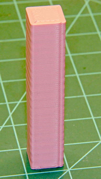
The LED lamps are much bigger than the halogen bulb, but they fit neatly into the housing diameter. All they needed was a bit more front-to-back room, which looked a lot like a chunk of PVC pipe. The housing screws together with a 1.5 mm thread that I can’t produce on my inch lathe; I’m still not set up for thread milling. This being a low-stress application with a lamp that ought to outlast me, I figured I’d just make the belly band slip-fit the two threads, glue it in place, and move on.
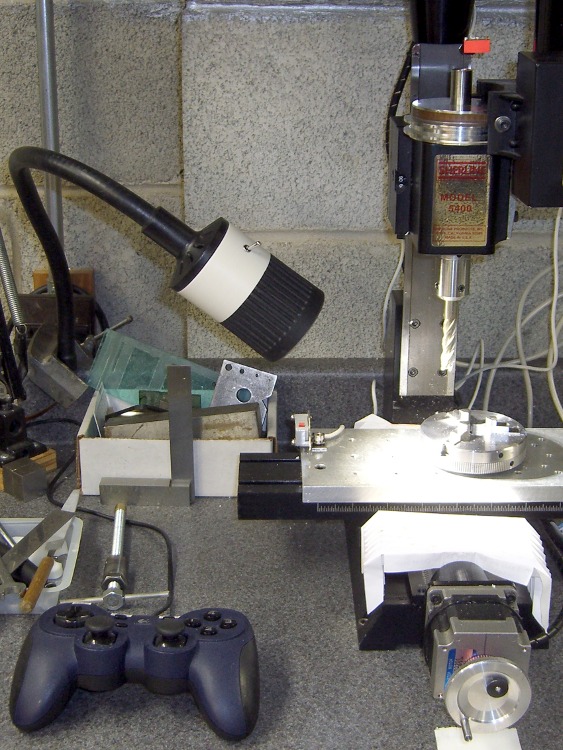
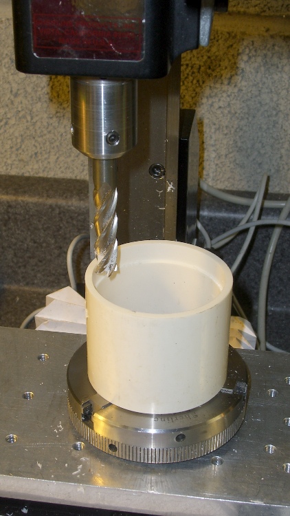
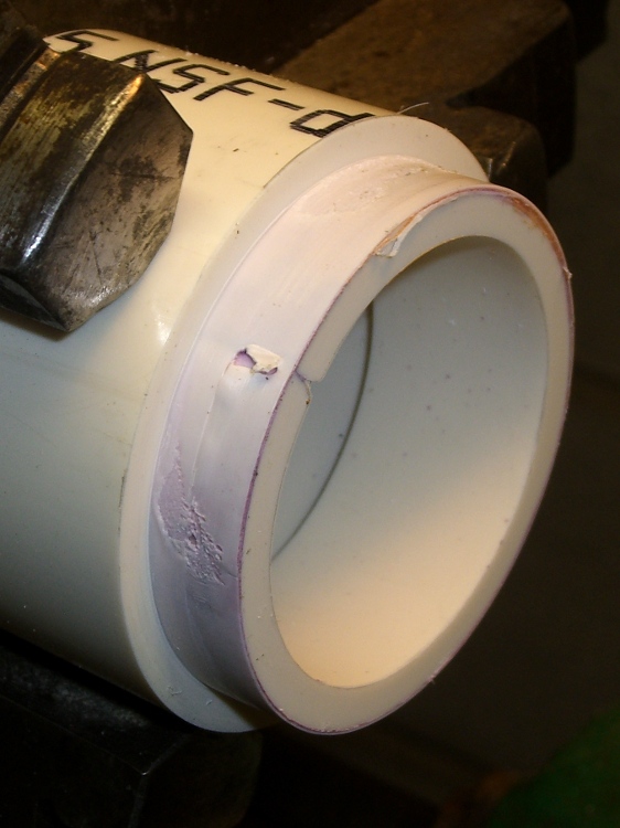
I sawed off a length of PVC pipe, faced off the ends in the lathe, then CNC milled a recess to clear the male threads on the gooseneck part (I hate precision boring in the lathe). Given the rather tenuous grasp of that 3-jaw chuck, I made two passes around the perimeter: pipe ID 52.1, thread OD 54.5, remove 1.2 mm all around, about 9 mm down.
Milling top recess
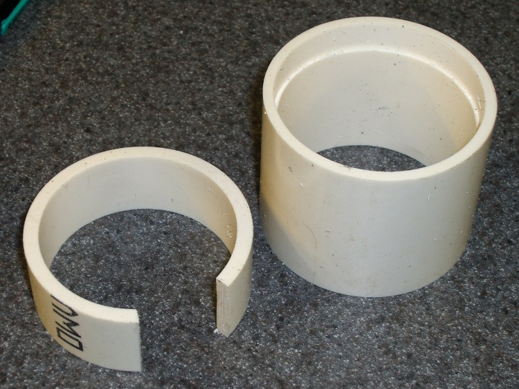
On the other end, the female thread ID = 52.2 and the pipe ID = 52.1, so I glued another ring of PVC pipe inside to provide enough meat to turn it down. Once again, saw off a ring, face the ends, then cut out a segment so that the OD circumference of the inner ring is just slightly smaller than the ID circumference of the outer pipe. The result looked like this:
PVC insert sizing
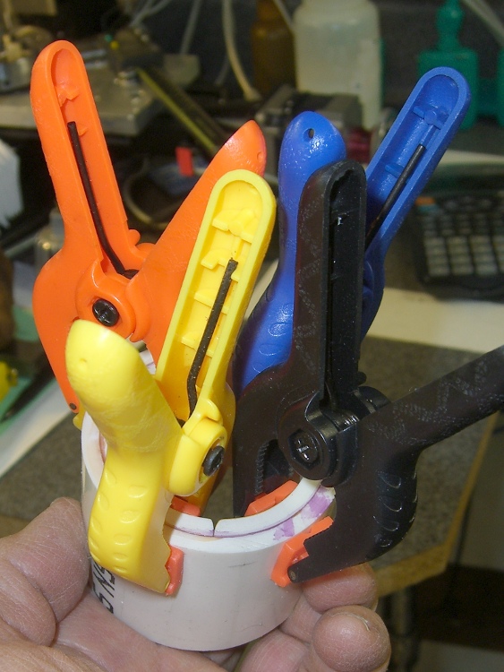
Apply a heat gun to the inner ring until it’s soft enough to stuff into the pipe, clamp it until it hardens, apply PVC cement, and clamp overnight. Contrary to appearances, the ends of the two pipes are flush at the surface. Once again, you cannot have too many clamps:
Clamped PVC insert
Turning down the outside to fit the threads shows just how little meat was left on that pipe:
Skinning down to the insert
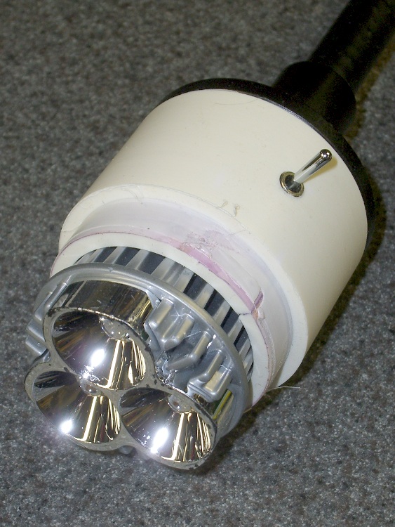
While it was chucked up (and despite my dislike of boring) I bored a bevel to accept the LED lamp and adjusted the OD so the lamp fit snugly between the end of the belly band and the lens holder on the front of the housing:
Floodlight in holder
The switch comes from the Parts Heap. A D drill puts a slightly undersized hole that’s just right for the threaded switch; I simply turned it in by hand. A length of zip cord carries the power up the gooseneck, where various ends get soldered to the switch and lamp.
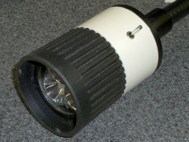
I applied some hot-melt glue to the threads and pushed everything together:
Finished LED Floodlight
The glass lens on the front fits in a molded holder with an annular air gap. The LED lamp housing has all those fancy cooling fins against the inner pipe, so there’s a bit of cooling air flow around the lamp and out through the rear black section. A thermocouple reports the lamp temperature gets up around 75 °C in a 14 °C shop; a 50 °C rise might be a tad warm in the summer, but we’ll see what happens.
The power supply came from the Parts Heap: a 12 V 1 A wall switching power supply in the shape of a wall wart. For now, the zip cord from the lamp terminates in a coaxial power jack that (amazingly enough) fits the wart’s connector, but I’ll eventually put a box in there somewhere.
Clamped the butt end of the gooseneck to the backsplash on the countertop under the mill and It Just Works!
The stock Zzipper fairing handlebar mount consists of an aluminum bar with a plate welded to each end at more-or-less the correct angle to match the fairing curve. The plate has a 1/4 inch hole in one end, wherein a 1/4-20 nylon machine screw clamps the fairing to the plate, with a nylon washer distributing the stress. That doesn’t cope well with the vibrations caused by riding around here, let alone our summer vacation trips on crushed-stone rail trails, and the fairings tend to stress-crack at the holes.
These 3D printed plates are just the latest in a long series of attempts to distribute the stress over a larger area. The outside view:
Fairing mount – outside
The open hole gets another screw to hold the plates in position. The bump on the far side is an Oozebane turd, about which more later.
The view from inside the fairing:
Fairing mount – inside
You can’t see the layer of black foam rubber salvaged from a mouse pad between each plate and the fairing. That should prevent any local stress concentration at the screw and ease the transition to the tapered plate edges.
The solid model looks about like you’d expect:
Fairing Mount Plates – Upper
The hole position depends on the fairing position, as the fairings have three holes. The pictures show the fairing on my bike; it’s in the lowest position, with the screw in the topmost hole. The OpenSCAD file has an option to put the holes where you need them.
The plates are only 8 layers thick, printed with 4 solid layers top and bottom to eliminate any fill. You could do the same by setting the fill to 100%, I suppose. Using 4 outer shells (3 additional) makes the flanged edge nice and flat and uniform.
The layer height is 0.33 mm, with w/t=1.7 for a width of 0.56 mm. Feed rate = 43 mm/s and flow rate = 255. DC Extruder, alas.
Running the first layer at feed = 0.5 and flow = 0.75 produces some fluffing in the fill, but there’s no way to get a lower flow from the DC extruder motor. Flow = 0.75 corresponds to PWM=191; anything lower sometimes fails to start the motor. If it starts, it’ll run, but … that’s not dependable.
I printed them on an aluminum plate for a nice flat bottom surface.
The OpenSCAD source code:
// Clamp plates for Zzipper fairing on Tour Easy recumbents
// Ed Nisley - KE4ZNU - Mar 2011

// Build with...
//	extrusion parameters matching the values below
//	4 outer shells
//	4 solid surfaces at top + bottom
//  slow feeds to ensure hole perimeters stick to fill

include </home/ed/Thing-O-Matic/lib/MCAD/boxes.scad>
include </home/ed/Thing-O-Matic/lib/MCAD/units.scad>

// Select hole layout
// The if statement seems to work only for CSG object trees
// Fortunately, I need only two different layouts...

HoleSelect = 1;						// 0 = his, 1 = hers

HolesTop 	= (0 == HoleSelect) ? [0,1,1] : [1,0,1];
HolesBottom = (0 == HoleSelect) ? [0,1,1] : [1,0,1];

// Set these to match the extrusion parameters for successful building

ThreadZ = 0.33;						// extrusion thickness
ThreadWidth = 0.57;					// extrusion width = ThreadZ x w/t

HoleWindage = ThreadWidth;			// enlarge hole dia by extrusion width

// Plate dimensions

HoleDia = 0.25 * inch;				// these are 1/4-20 bolt holes
HoleSpace = (1) * inch;				// center-to-center spacing
									//  usually 1 inch, but 15/16 on one bike

CornerR = 5.0;						// corner rounding

Layer1X = 90;						// against fairing surface
Layer1Y = 32;
Layer1Z = 2*ThreadZ;

Layer2Margin = 1.5;					// uncovered edge
Layer2X = Layer1X - 2*Layer2Margin;
Layer2Y = Layer1Y - 2*Layer2Margin;
Layer2Z = 3*ThreadZ;

MountX = 46.3 + HoleWindage;		// handlebar mounting bracket end plate
MountHoleSpace = 13.0;				//  end to hole center
MountY = 16.3 + HoleWindage;
MountZ = 4*ThreadZ;					// recess depth
MountCap = 3.0;						// endcap arc height
MountR = (pow(MountCap,2) + 0.25*pow(MountY,2)) / (2*MountCap);	// ... radius

Layer3Margin = 1.5;
Layer3X = Layer2X - 2*Layer3Margin;
Layer3Y = max((Layer2Y - 2*Layer3Margin),(MountY + 8*ThreadWidth));
Layer3Z = 3*ThreadZ;

PlateZ = Layer1Z + Layer2Z + Layer3Z;

// Convenience settings

BuildOffset = 3.0 + Layer1Y/2;		// build Y spacing between top & bottom plates

Protrusion = 0.1;					// extend holes beyond surfaces for visibility

//---------------
// Create plate with selectable holes

module Plate(hs) {

  difference() {

	union() {
		translate([0,0,Layer1Z/2])
		  roundedBox([Layer1X,Layer1Y,Layer1Z],CornerR,true);
		translate([0,0,Layer1Z + Layer2Z/2])
			roundedBox([Layer2X,Layer2Y,Layer2Z],CornerR,true);
		translate([0,0,Layer1Z + Layer2Z + Layer3Z/2])
			roundedBox([Layer3X,Layer3Y,Layer3Z],CornerR,true);
	}

	if (0 != hs[0]) {
	  translate([-HoleSpace,0,PlateZ/2])
		  cylinder(r=(HoleDia + HoleWindage)/2,
					h=(PlateZ + 2*Protrusion),
					center=true,$fn=10);
	}

	if (0 != hs[1]) {
	  translate([0,0,PlateZ/2])
		  cylinder(r=(HoleDia + HoleWindage)/2,
					h=(PlateZ + 2*Protrusion),
					center=true,$fn=10);
	}

	if (0 != hs[2]) {
	  translate([HoleSpace,0,PlateZ/2])
		  cylinder(r=(HoleDia + HoleWindage)/2,
					h=(PlateZ + 2*Protrusion),
					center=true,$fn=10);
	}

  }

}

//---------------
//-- Build the things...

translate([0,BuildOffset,0]) Plate(HolesTop);

translate([0,-BuildOffset,0])
  difference() {
	Plate(HolesBottom);

	translate([-(HoleSpace + MountHoleSpace - MountX/2),0,PlateZ - MountZ/2 + Protrusion/2])
	  intersection() {
		cube([MountX,MountY,(MountZ + Protrusion)],center=true);
		union() {
		  cube([(MountX - 2*MountCap),MountY,(MountZ + Protrusion)],center=true);
		  translate([ (MountX/2 - MountR),0,0])
			cylinder(r=MountR,h=(MountZ + Protrusion),center=true);
		  translate([-(MountX/2 - MountR),0,0])
			cylinder(r=MountR,h=(MountZ + Protrusion),center=true);
		}
	  }
  }
I loves me my Thing-O-Matic, despite its annoyances…
[Update: Stepper extruder parameters and a tweak to make the mount plate track the hole position correctly.]