Ed Nisley's Blog: Shop notes, electronics, firmware, machinery, 3D printing, laser cuttery, and curiosities. Contents: 100% human thinking, 0% AI slop.
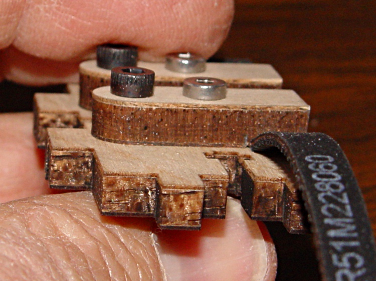
The laser-cut plywood clamps holding the timing belts to the drive ribs slant diagonally across the rib + belt and secure one edge of the belt.
Belt clamp before modification
While this certainly works, it offended my sensibilities and is probably why the instructions call for that low-profile bolt.
Introducing the belt clamp to Mr Disk Sander provided just enough relief to clear the belt’s backing, while not making for a sloppy fit. In round numbers, if you barely trim off the plywood veneer it’ll be about right. Use an ordinary file if one of Mr Sander’s relatives doesn’t live in your shop.
Modified belt clamp
And then it works just like it should. If you were even fussier, you might chamfer the outer edges to allow the belt to lie flatter against the rib, but that’s in the nature of fine tuning. At least on my Thing-O-Matic, there’s plenty of air between a standard bolt head and the adjoining carrier rod.
Modified belt clamp in place
This is obviously not something you should dismantle your Thing-O-Matic for, but if you’re in the delightful position of facing that mountain of parts, this is perfect timing.
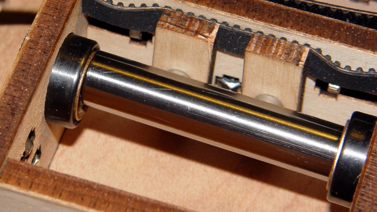
The socket-head cap screws securing the ball bearings that ride on the left-side Y stage rod prevent the X axis motor from sliding rightward along its mounting slots. The rightmost position, as enforced by the SHCS heads, makes the belt far too tight.
This suggests that the ball bearing assembly was an afterthought, perhaps solving the same overconstrained rod problem as I fixed in the X axis stage. The as-built motor position pulls the X axis belt just slightly less taut than a banjo string, which isn’t a Good Thing.
The solution is to replace the four SHCS with pan-head screws to get a bit more clearance. Fortunately, my Parts Heap had some salvaged 3 mm screws of sufficient length, so I avoided a trip to the Big Box retailer. Rather than put everything together and discover the heads were still too tall, I ground them down so just the barest hint of the slot remained:
Modified pan-head screw
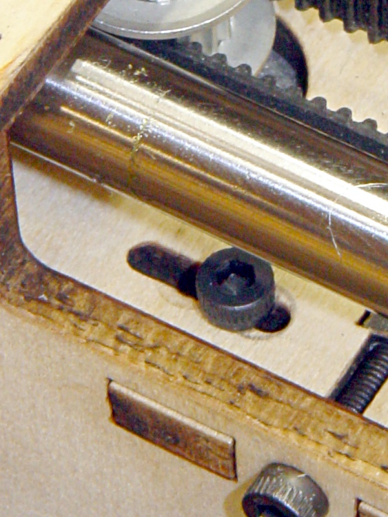
That provided enough clearance to make the X axis belt entirely slack, which means I probably didn’t have to grind the heads in the first place. In any event, the proper position looks more like this:
Adjusted X axis motor position
If you look very closely, you can see the marks from the original position near the middle of the slots. Here’s a blown-up and contrast-stretched view:
X axis motor mounting slot – detail
Those few millimeters make all the difference in the world: the belt is now decently tight, the motor responds well, and all is right with the world.
Many of the discussions in the Makerbot Operators Google Group involve bad prints due to “missing steps”, overheated stepper motors, and other motion-related maladies. The proposed cures generally don’t address the real problem, which has nothing to do with slipping belts, inadequate motor current, or general hygene.
The problem is rod alignment, which is not guaranteed by the laser-cut plywood frame.
The Thing-O-Matic guides all its moving parts with bronze bushings sliding on polished steel rods to ensure low friction and exceedingly long life. Unfortunately, you can easily assemble a TOM with X and Z (and sometimes Y) stages you can barely push by hand: I’ve done it!
The symptoms involve the actual position gradually departing from the commanded position: a G0 X10 Y20 command might actually put the extrusion nozzle at X=9.9 Y=20. That error produces a small offset along the X axis that gets worse on successive layers and eventually causes the object to resemble the Leaning Tower of Pisa. The TOM can’t correct the error, because it doesn’t know where the stage actually stops after a command: the steppers run open-loop.
This can’t be due to a slipping belt, because a toothed timing belt can only skip by multiples of the tooth pitch: a one-tooth “skip” means a 2 mm positioning error that’s immediately obvious. In any event, if the belts are that loose, you have other problems.
It could be a loose belt drive pulley on the motor shaft, but that will produce random offsets in both directions as the setscrew gradually chews a slot around the motor shaft. If that’s the symptom, fix it now because you won’t be able to get that pulley off after the setscrew finishes raising a burr around the shaft.
The errors generally happen in the X direction because the X stage slides on two rods, each of which is fixed at four places: both ends of the Y stage and both ends of the X stage. The tech term for this is “overconstrained”: two points determine a line, but here we have a line that must pass through four points.
If the rod-to-rod spacing in those four places isn’t exactly equal, then the X stage bushings will bind on the rods. Alas, tolerance creep in the plywood and maybe a bit of off-center sanding when you fitted the bushings into the plywood can produce exactly that situation.
The Y stage doesn’t have this problem, because the right side rides on bushings and the left side rides on three ball bearings, making it not so sensitive to
horizontal misalignments.
Diagnosing this in an assembled Thing-O-Matic presents a major nuisance, but is well worth the effort. Release the X stage drive belt by loosening the X axis motor bolts (or, if you haven’t modified those bolts, by dismounting the idler pulley, which means extracting the whole XY assembly from the TOM and taking it apart) so the carriage can slide without moving the belt and turning the motor.
If you can move the X stage back and forth along the entire length of its travel by pushing gently with one fingertip, it’s all good. Most likely, you must apply far more force than that, as was the case in my TOM after I first assembled it: moving the X stage required quite a shove and it definitely didn’t slide freely.
Fixing this is straightforward, at least with the entire X and Y assembly out of the TOM. There are two steps:
Align the X stage bushings so the rods move freely
Align the Y stage mounting points to match the X stage spacing
To begin…
Remove the X stage from the Y stage, then remove the base plate so you can see the inside end of all the bushings. Slide each rod out of one bushing, then try to slide it back. I predict it’ll look something like this:
Misaligned X Axis bushing
The rod wants to avoid the hole in the left bushing. Orbit it around in the right-side bushing until it’s well centered on the left bushing. You want it to look like this when it approaches that bushing:
Aligned X Axis bushing
When it’s properly aligned, slide it in. You should then be able to bat the rod back and forth with your fingertips; if it doesn’t slide freely, slide it out of one bushing, apply more wiggly jiggly action, and get it aligned. Bat the rod back and forth a few times to get a feel for free motion, then repeat for the other rod.
About lubrication: the bronze bushings are self-lubricating, but a bit of oil won’t do any harm. Machine oil is good, cooking oil is bad, butter is terrible. If the rods feel nice and slippery, it’s fine.
When both rods slide freely, pop the X stage back into the Y stage. This is actually possible with both rods in the X stage, although now that you know what you’re looking for, you can slide them out, put the X stage inside, then slide the rods back in again. Remember, you want free rod motion within the X stage itself.
With the rod ends captured in the Y stage, put the front end caps on to hold that rod in place. Slide the X carriage to the right end of its travel (hold the loose rear rod!), then push the rear rod out of the one end piece by pushing it into the plywood while supporting the X carriage. Most likely, the rod will go spung a fraction of a millimeter horizontally as it exits the end piece (you control the vertical offset by supporting the carriage).
That’s the rod’s way of telling you that the end hole is in the wrong position. If the rod slides easily in and out of that hole, then it’s all good. If it doesn’t, then sand the offending side of the hole until the rod slides easily into the hole.
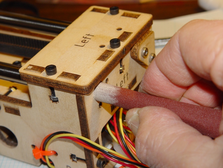
I wrapped a length of sandpaper around a brass tube so the sandpaper formed a cylinder nearly the same diameter as the rod, which prevents sanding a notch into the plywood that makes things worse. Remove wood from the side of the hole, not the top or bottom:
Adjusting rod hole position
When the rod slides freely into the hole with the X stage at that end, slide the stage to the other end and repeat the process. You must do both ends of travel to get all four constraining points lined up properly.
Recheck the rod fit at both ends of travel, then install the end caps.
The X stage should now slide back and forth with just light finger pressure.
If you overdo the sanding, shim the loose side of the hole with aluminum foil and a dab of adhesive. If the rod rattles around, that’s bad; add an all-around shim and put a very thin slice of foam under the end cap to calm it down.
Verily, it is far better to sand a little and check a lot!
You can apply the same process to the Z axis stage and rods. Remove the bolts holding the motor to the top plate, then verify that:
The Z stage freely slides up and down the rods
The rods align with their mounting holes with the Z stage each end
Sand the holes for one of the rods to make that answer come out right, too.
Those bronze bushings work wonderfully well, but only when the rods are
exactly parallel and properly spaced.
[This post is a revised, corrected, and expanded version of a comment I posted on the MBO group.]
This was more tedious than it ought to be, but OpenSCAD now runs on my desktop box and uses OpenGL 2.2, courtesy of a not too obsolete nVidia GeForce 9400 dual-head card.
OpenSCAD has a slew of pre-reqs, most of which were already installed. However, the openscad and cgal non-packages live in the Arch AUR collection, so they required manual twiddling to install.
The pre-reqs:
cgal, which in turn requires cmake via pacman
opencsg
The recommended PKGBUILD patch is easy enough to do by hand.
The final build step takes ten minutes using both cores, but the final result uses OpenCSG the way it should.
Oddly, the OpenSCAD rendering process for the few objects I’ve checked takes longer than on the laptop. Weird.
This does not get the most recent build from the developers, but it’s close enough for my simple needs right now. The mailing list archive is invaluable.
Then there was the laptop saga. Maybe the reason the laptop is faster is that it’s not actually using OpenCSG at all.
The Thing-O-Matic Motherboard rides atop an Arduino Mega (with the auto-reset option disabled), drawing most of its power from the hulking ATX connector at one end. The Mega draws power from the ATX +12 V supply and produces +5 V through its on-board regulator.
As I noted there, that regulator runs surprisingly hot when fed from +12 V, even without any additional current flowing to the Mega’s pins. The solution here required another search through the parts heap, which eventually disgorged a small heatsink that was, I think, intended for a 16-pin DIP, although I obviously added the hole for some other, long-forgotten purpose.
Motherboard regulator heatsink
A bit of fin-bending to clear the (unused) power entry jack, a dab of JB Kwik epoxy, and a clamp to keep it in place while the epoxy cures:
Clamping the Motherboard regulator heatsink
You won’t have such a heatsink, but any similarly shaped chunk of metal, even without fins, should suffice. Nothing critical about it, as long as it clears the Motherboard that will be plugged atop the Mega; you’re just increasing the surface area for heat dissipation.
The Motherboard and Mega sit in the large opening across the Thing-O-Matic’s baseplate from the ATX supply’s fan intake, where they get plenty of cooling air. Do a before-and-after test with a fingertip on the regulator to feel the improvement for yourself.
This is, admittedly, just a feel-good tweak, but a cool regulator is a happy regulator. Spread the joy…
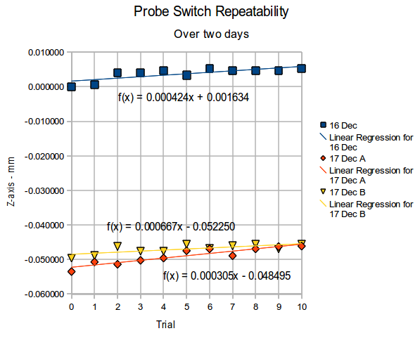
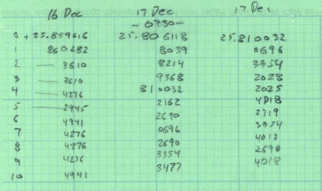
Re-running that probe length switch test a few weeks later produced these results for three trials over the course of two days.
Probe Repeatability – Dec 2010
The Z-axis differences are all relative to the first reading on the first day, so this includes whatever Z-axis changes take place without doing anything else on the mill in between the tests. I turned the power off after making the first set of measurements, so the steppers restarted with up to a plus-or-minus one full step offset; that works out to:
(0.050 inch) * (1 rev / 200 steps) = 0.00025 in = 0.0064 mm
Because EMC2 doesn’t actually know where the stepper is, any uncommanded motion will show up as an offset when the probe switch trips, which is exactly what we see here.
Two things of interest:
The -0.05 mm offset between the two days could well be part of a single step offset
Successive probe positions during a single test don’t change by hardly anything at all
(I’m giving a talk and show-n-telling my Sherline CNC milling machine at Cabin Fever Expo right about now, so having this data readily available seemed prudent. The talk & handouts are there.)
The man with one thermometer knoweth the temperature
The man with many thermometers knoweth not the temperature
Drilling the isothermal block
Given the five thermocouples and their meters shown there, plus the Thing-O-Matic’s thermocouple, I had six different temperatures. They’re close, but we can do better than that.
The general idea is to put all the thermocouple beads in close proximity so they share the same temperature, record their opinions to various temperatures, then figure out an equation that adjusts their disparate opinions to reflect consensus reality.
I cranked out an isothermal block on the Sherline mill, using EMC2’s exceedingly handy polar coordinate notation to get a nice hexagon. Touch off XYZ=0 at the middle of the block, then center-drill and drill:
For lack of anything better, 3000 rpm with a drill matching the ID of the brass tubes, plus dripping cutting fluid as needed.
Thermocouples in block
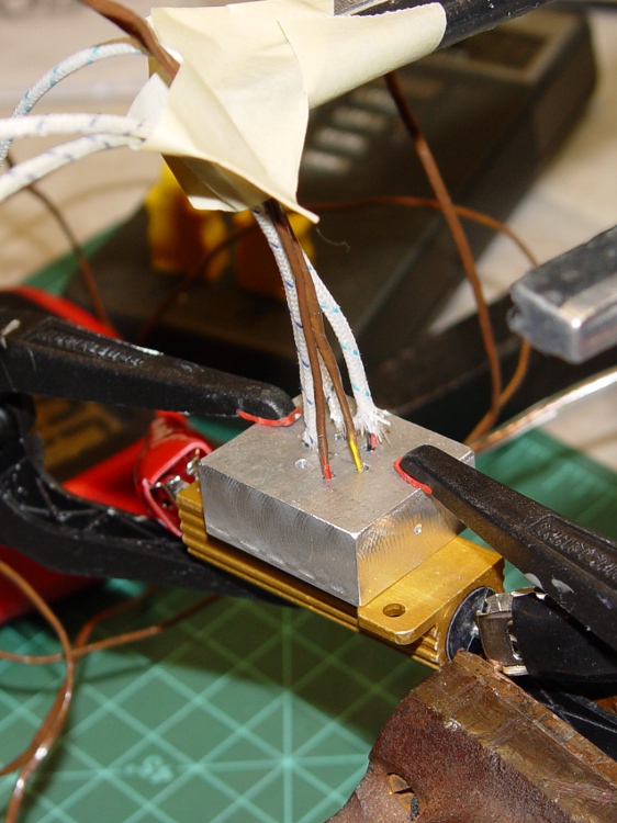
I used a 6 Ω 50 W resistor (the adult version of the resistors on the Thing-O-Matic / MK5 head) as a heat source, clamping the block to the resistors with plastic clamps to provide mechanical force and thermal isolation. Good idea, bad implementation: as you’ll see, those little red tips melt at a rather low temperature.
The TOM thermocouple bead will fit into the empty hole.