The Smell of Molten Projects in the Morning

Ed Nisley's Blog: Shop notes, electronics, firmware, machinery, 3D printing, laser cuttery, and curiosities. Contents: 100% human thinking, 0% AI slop.

Tag: CNC

Making parts with mathematics

  • Thing-O-Matic: MBI Stepper Motor Analysis

    After pondering the stepper motor data collected there and the driver data there, plus running some experiments with different motors, I’ve concluded that the MBI stepper motors aren’t appropriate for the Thing-O-Matic. This post summarizes my doodles and provides some background and justification for what I’ve been doing…

    During the next week or two I’ll continue writing up the results of installing better stepper motors in my TOM, plus some mods required to take advantage of the improved performance. I’ll do a wrapup of the new motors when everything’s settled down and I (think I) understand what’s going on.

    The ideal situation

    This diagram from page 15 of the Allegro A3977 datasheet shows how the current varies in each winding during the course of 32 microsteps. The motors have 200 full steps/rev and 1600 microsteps/rev, so this diagram repeats 50 times during the course of one complete shaft rotation.
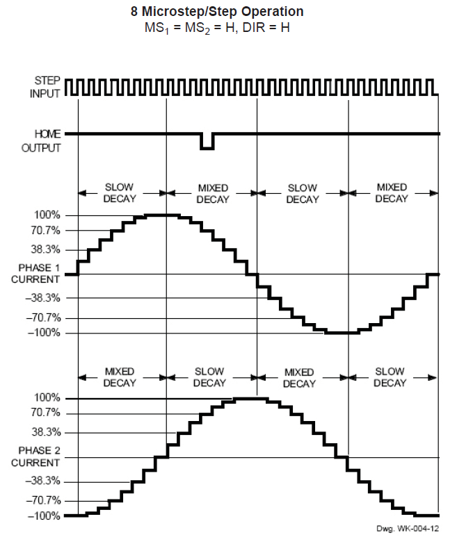
    Allegro A3977 microstepping current waveforms
    Allegro A3977 microstepping current waveforms

    The peak current of each waveform corresponds to the REF pot setting on the MBI driver board:

    current in amperes = (REF pot voltage) / 2

    That peak current must not exceed the motor’s rated Maximum Current, because the winding resistance dissipates that much power as heat. The maximum temperature occurs deep in the windings, far from the metal part of the armature, so blowing air on the motor helps, but does not cure, an overtemperature problem.

    The driver adjusts the current in each winding to generate an approximation of a sinusoid waveform for each microstep. Because the motor torque varies directly with the winding current, the REF pot sets the maximum torque available from the motor.

    The A3977 driver controls the current by switching the MOSFETs on and off: on = increasing current, off = decreasing current. You can fiddle with the rates of increase and decrease, but those are all in the nature of fine tuning. What’s important is that the A3977 shuts off the winding current when it exceeds the product of the REF pot setting and the sinusoidal value for the microstep, then turns it back on when it falls below a somewhat lower level.

    Therefore, the current isn’t actually constant: the whine you hear when the motors are standing still is an audible harmonic or sub-harmonic of the switching frequency. That’s not a bug, it’s a feature!

    At the microsteps corresponding to the peaks of each sinusoidal waveform, one winding carries the maximum current and the other winding carries zero current. There are 200 such positions, each corresponding to one full motor step. At those points, the armature holds the rotor in position with the much-quoted Holding Torque.

    For all other microsteps, the A3977 controls the Pythagorean sum of the two currents to equal the maximum current setting. The two currents pull the rotor toward two adjacent full-step positions, with the actual (nominal) rotor position determined by a bit of trig.

    The power dissipation in the motor at every microstep is therefore:

    (peak current)2 x (winding resistance)

    All that applies to the DC situation with the motor halted at a particular microstep. In order to turn the rotor, the drive must change the winding currents to the values for the next microstep.

    The motor windings are basically inductors with energy stored in their magnetic field, so the current cannot change instantly. The ratio of the inductance (L) and the total circuit resistance (R) is the time constant, abbreviated with a Greek tau (τ):

    τ = L/R

    The current change from one microstep to the next requires 3 time constants to settle within 5% of the final value and 5 time constants to settle within 1%. Those are characteristics of the exponential function and have nothing to do with the particular circuit; once you know the time constant, you know what’s going to happen.

    The voltage applied to the motor winding determines the final value of the current that you use with the time constant. Microstepping drivers expect to apply a voltage far higher than the winding’s rated voltage, then limit the current to the winding’s rated value: the current never reaches the “final value”, but that’s still what you use in the computation. If the supply voltage equals the winding’s rated voltage, then the final value is simply the winding’s rated current.

    The MBI Situation

    The MBI motors (all of them, XYZ and Stepstruder) in a Thing-O-Matic do not operate like that. I’ll use the XY motors as examples, but feel free to run the same analysis on the others.

    To summarize the datasheet values:

    • Inductance L = 44 mH
    • Resistance = 35 Ω
    • Rated voltage = 14 V
    • Rated current = 400 mA

    The motors operate from a +12 V supply, so the maximum winding current will be at most 12 / 35 = 340 mA. The actual power supply voltage seems to around 11.5 V with the heaters running, the A3977 MOSFETs (inside the chip) have a total on-state resistance of about 800 mΩ, and I’ll assume another ohm of wiring resistance along the way. All that reduces the actual maximum current to around 300 mA; I’ll use that, because it’s within 10% off the actual value.

    The MBI-recommended REV voltage setting of 1.5 V sets a 750 mA output current. However, there’s no magic involved: the motors cannot draw more than 300 mA in a Thing-O-Matic, no matter what the REF trimpot may call for.

    With the REF trimpot set to 750 mA and the maximum current limited to 300 mA by the circuit, the A3977 cannot produce the correct current for most of the microsteps. Whenever the microstep current exceeds 300 mA, the A3977 cannot make that happen.

    This diagram shows the actual winding current in the MBI motors for each of the 32 microsteps in four full motor steps:

    Allegro A3977 waveform - current saturation
    Allegro A3977 waveform – current saturation

    The 100% level corresponds to the 750 mA set by the REF trimpot and, as above, the nice sinusoids show the target current for each microstep. The red line shows the actual current for each microstep, none of which can exceed the 300 mA limit. That limit corresponds to 300/750 = 40% of the maximum, just slightly over the 38.3% for the second microstep in each sequence.

    The pink zones mark the microsteps where both windings become current-limited to 300 mA. During those microsteps, the current in the windings doesn’t change and the motor cannot move. Of the 32 microsteps in each group of four full steps, the motor can move during only 16.

    The horrible sounds you hear from an MBI motor happen as the rotor encounters those pink zones: the rotor literally jams to a stop when both windings limit at 300 mA, remains immobile while the currents remain steady, then jerks across the 4 microsteps in the pink zone when the current in one winding drops below 300 mA. This is obviously not conducive to smooth motion or high torque.

    Try this: reduce REF to, say, 400 mV to limit the peak current to 200 mA. Run the motor slowly, because it won’t have much torque, and listen. Set REF back to 1.5 V, run it at the same speed, and listen.

    The power dissipation for all the microsteps in the pink rectangles is:

    2 x (300 mA)2 x 35 = 6.4 W

    The factor of 2 comes from the fact that both windings carry 300 mA in that condition.

    The motor’s rated maximum power is:

    (400 mA)2 x 35 = 5.6 W

    There’s no factor of 2 because the rating applies to one winding carrying the rated current.

    During the other microsteps the power drops slightly, with the best case when one winding carries zero current:

    (300 mA)2 x 35 = 3.2 W

    That’s why MBI motors overheat: they operate at the ragged edge of their power limit while tucked inside a thermally insulating plywood box. If the motor stops on a microstep inside those pink zones, it’ll dissipate 6.4/5.6 = 114% of its rated power.

    Changing the current between microsteps also poses a problem. The time constant for the MBI XY motors is:

    τ = 44 mH / 35 Ω = 1.3 ms

    That means the current settles within 5% in 4 ms and 1% in 6 ms.

    Stock Thing-O-Matics move at about 30 mm/s. The motor pulley has 17 teeth and the belt has teeth on a 2 mm pitch, so the motor must turn at 1 rev/s to move the stage at 34 mm/s. With 1600 microsteps/rev, each microstep takes 625 µs, which is half the time constant.

    I think you can see where this is going…

    The microsteps outside the pink zones could have active current limiting, because the A3977 has some voltage headroom. The first microstep has a current limit 20% of the 750 mA maximum (set by the trimpot = what you want) = 150 mA.

    The current starts rising toward the actual 300 mA maximum (set by the supply voltage and winding resistance = what you get) and after 625 µs it reaches:

    300 mA × (1 - e-0.5) = 120 mA

    So the current doesn’t quite reach the target and the A3977 doesn’t get a chance to do active current limiting.

    The next microstep has a 38% current limit that sets a target of 285 mA, marginally below the 300 mA limit set by the winding resistance. The A3977 continues to apply the full supply voltage, so the winding doesn’t notice anything’s changed and the current continues to rise. At the end of the second microstep the current has reached:

    300 mA × (1 - e-1) = 190 mA

    Which is about 2/3 of the target and the A3977 still doesn’t do active current limiting.

    The full analysis is messier than that, but what you see is pretty close. I won’t go into what happens when the A3977 is trying to reduce the winding current, but a similar analysis applies.

    Also, when the motor rotates slower the microsteps last longer and the current can get closer to the target value. Print at 15 mm/s to get microsteps about 1 time constant long; that’s still short, but it’s better.

    If the motor stops on a microstep outside the pink zones, then the two winding currents will eventually exceed the values for that microstep and the A3977 will begin active current limiting: that’s when you hear the chopper whine. However, if the motor stops on a microstep inside the zones, then it’s dead silent: the currents never reach the level where the A3977 can apply active current limiting.

    Because torque is proportional to current, the motor never delivers its rated torque in any microstep while it’s turning. The motor datasheet includes this torque-speed curve:
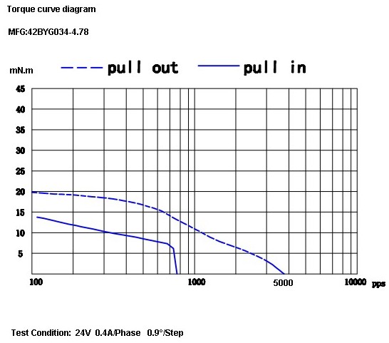
    Cupcake TOM Stepper Torque Curve
    Cupcake TOM Stepper Torque Curve

    The much-quoted Holding Torque is irrelevant. That measures the motor’s ability to hold its position with an external torque applied to the shaft. Unlike CNC milling machines, 3D printers do not impose torques on the XY motors due to forces from a cutting tool.

    What’s important is the bottom curve showing the pull-in torque: the torque available to accelerate the load from a dead stop to the speed shown along the bottom, given in full-step pulses per second.

    At 1 rev/sec the motor sees 200 full steps/sec, at which speed the pull-in torque is about 12 mN·m. However, that’s at the 400 mA full rated current applied from a 24 V source through a current-limiting driver. Because the maximum torque depends on the current and the resistance limits the maximum current to 300 mA, the maximum pull-in torque scales to 9 mN·n.

    I’ll grant the possibility that there’s a misprint and Kysan simply dropped a zero. Pull-in torque around 150 mM·m seems more common with short NEMA 17 motors, but the data sheet is what the data sheet is. The motors behave as though they have no mojo, which leads me to believe the printed word.

    Anyhow, that torque assumes the driver applies the proper winding current in each microstep, which, as you’ve just seen, doesn’t happen. Oddly, the MBI motors provide the highest torque in the pink zones, where the Pythagorean sum of the resistance-limited winding currents is:

    √(2 x 300 mA2) = 420 mA

    So the motors run in a crippled full-step mode that produces more-or-less the rated torque only when the motor isn’t moving, while dissipating too much power. When the motor is moving, the current never reaches the proper level.

    The measurements I made when I had the printer apart indicate that the X and Y stages require far more torque than the MBI motors can provide, even if they were driven correctly. The fact that they work at all has more to do with good luck and spec tolerances than anything else.

    The inadequate torque also answers the question of whether a higher power supply voltage will improve things: no, not much. A 24 V supply (as specified in the datasheet!) will permit operation at the rated current with correct microstepping, but that torque is still far too low.

    I don’t have any inside knowledge, but I think what happened is that these motors date back to the Cupcake printer, which used a simple H-bridge without active current limiting. For that type of driver, the rated voltage of the winding must equal the supply voltage, because the winding resistance provides the current limiting.

    Using A3977 drivers seemed like a simple upgrade to produce the Thing-O-Matic, but a microstepping driver must apply a voltage much higher than the winding’s rated voltage in order to get fast current changes and apply active current limiting. The old motors simply aren’t suited for the new drivers.

    Tomorrow: what better motors can do for a Thing-O-Matic.

    I’m certain I’ve made at least one error in what you’ve just read; comments, criticisms, and corrections are welcome. However, before you comment, RTFM for the A3977 driver, the MBI stepper motors, and any other hardware you’re proposing. Run the numbers first, OK?

    Update:  A reader suggests a rule of thumb relating voltage to inductance …

    Marris Friemannis of Gecko drive fame quotes this rule of thumb (http://www.mechmate.com/forums/showthread.php?t=1618)

    Drive Supply Voltage = 32 * √mH Inductance of the motor

    So in case of 44mH motor, correct voltage would be in excess of 200V, which I choose read as “the motor is junk” :)

    In the stuff 3D printers use, single digit mH values at 24V seem to work fine.

  • NEMA 17 Shaft Adapter

    NEMA 17 5mm to 0.1875 inch shaft adapter
    NEMA 17 5mm to 0.1875 inch shaft adapter

    The NEMA standards for stepper motors don’t specify the shaft dimensions, alas. While most NEMA 17 steppers have 5 mm shafts, the X and Y axis motors in a Thing-O-Matic have 3/16 inch shafts: MBI belt pulleys with 4.76-ish mm ID won’t fit on 5 mm OD shafts.

    (Note: the “17” in NEMA 17 means the mounting holes are on a more-or-less 1.7 inch circle. The side of the motor frame will be close, but that’s not the controlled dimension. Some relevant diagrams live there.)

    I plan to replace the Y axis stepper with a better motor (I got a set of three, one of which is now driving the stepper extruder), which means either buying a new pulley or having some Quality Shop Time. Plus, a bit more length on the Y axis shaft than what comes standard would be a Good Thing, too.

    [Update: From the motor label, not that you’ll ever find one like it…

    • 38 mm case
    • Minebea-Matsushita 17PM-K150-P1V
    • No T6824-02

    ]

    So I built an adapter from 5/16 and 3/16 rod with a setscrew to grab a flat on the stepper shaft and a pin for the torque. The larger rod turned out to be La Salle Fatigue-Proof steel, not that it matters, and the smaller rod is plain old W-1 Water Hardening Drill Rod, both from Brownell’s, a long time ago in a universe far away. You could turn and drill the adapter from a single length of 5/16 rod if you prefer, but take some care to maintain the alignment.

    A bit of lathe & Sherline CNC work:

    • Face one end of the 5/16 rod
    • Drill half an inch with a #9 drill (0.196 + runout = 5 mm)
    • Drill another quarter inch with a #12 drill (0.189 = 4.8 mm)
    • Saw off 3/4 inch, face the raw end
    • Saw & face an inch of 3/16 rod
    • Epoxy little rod in big rod, set upright, wait overnight
    • Cross drill #43 and tap 4-40 near big end
    • Cross drill #56 for 0.045 music wire pin
    • Chamfer pin hole, clean, epoxy pin in place, wait overnight
    • File two flats on 3/16 shaft for MBI pulley setscrews
    Tapping shaft adapter
    Tapping shaft adapter

    I grabbed the small rod in the vise with the large rod resting on the top of the jaws while the epoxy cured, figuring that it’d be pretty much self-aligning. Not that a few mils one way or the other will matter, as it’s driving a timing belt in a flexy machine anyway.

    Cross-drilling the pin hole required eyeballing the center of the length of 3/16 rod within the 5/16 rod. It’s not critical, but avoid missing the poor thing entirely. You want to minimize the nested length, so as to keep the adapter as short as possible, but keep at least one diameter (3/16 inch) so as to maintain alignment.

    Tapping should involve a bottoming tap, but I used what I had and it worked out OK.

    Now, one reason I was willing to do this is that the stock Y axis motor shaft was already too short. As nearly as I can tell, the TOM dimensions were set before MBI started shipping those cork sound-deadening plates, because the shaft is recessed into the pulley by about the thickness of that plate.

    The MBI pulleys are an extremely tight fit on a 3/16 inch rod, so, rather than forcing the pulley, I enlarged the hub with a #12 drill (same as in the adapter) to get another 1.5 mil of clearance; it’s now an easy slip fit on the rod.

    Drilling MBI motor pulley
    Drilling MBI motor pulley

    Anyhow, the bottom flange of the pulley is 17 mm above the ridge on the motor and this one worked out to a bit over 20. No problem, I can just lower the motor a little bit, flip the pulley over to get the setscrew end of the hub on the top, and it’ll have plenty of room. A bit more shaft is much better than not enough, sez I.

    Y axis motor shaft extension
    Y axis motor shaft extension

    The motors came from the usual eBay seller complete with a squishy silicone sound deadening panel that turned out to be exactly the right thickness, when stacked atop a cork sheet, to put the pulley where it needed to be. I cut a second cork sheet, so as to isolate the bolt heads from that acrylic body panel, and it’s all good.

    Y axis motor with shaft adapter
    Y axis motor with shaft adapter

    Now, to print a suitable test object…

  • Skeinforge Build Parameters

    The extrusion settings, more or less, kinda-sorta, for the latest objects:

    • Layer thickness 0.33 mm
    • Perimeter w/t = 1.75 = 0.58 mm
    • Fill w/t = 1.65 (or as needed)
    • Feed 40 mm/s
    • Flow 2 rev/min with geared stepper
    • Perimeter feed/flow 75% of normal (probably not needed)
    • First layer at 20% of normal feed & flow
    • 210 °C (some at 220 °C) Thermal Core
    • 120 °C build platform (lower at plate surface)
    • Reversal: 20 rev/min, 90 ms reverse & push-back (lower better?)
    • Fill: 2 extra shells, 3 solid surface layers, 0.25 solidity, 0.3 overlap
    • Thread sequence: Loops / perimeter / infill
    • Cool: slow down, minimum 15 sec/layer
    • Bottom / splodge / stretch disabled

    Wouldn’t it be great if you could export all that stuff to a text file in a readable format? The CSV files come close, but they’re not really meant for human consumption.

    Subject to revision, your mileage may vary, past performance is no indication of future yield, perfectly safe when used exactly as directed, shake before using, don’t touch that dial!

  • HBP + Aluminum Build Plate + ABS Film = Win!

    A close look at the first few layers of some recent objects shows why I’m willing to put up with all the hassle described over the last few weeks.

    For small objects, take a look at my build of coasterman’s calibration set:

    50 mm tower - build detail
    50 mm tower – build detail

    Leach field pipe plug:

    Leach field plug - build detail
    Leach field plug – build detail

    Prototype X rod follower:

    X Rod Follower - build detail
    X Rod Follower – build detail

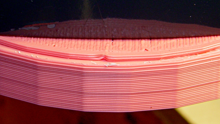
    Microscope LED ring light (two pieces glued on the obvious line):

    Microscope ring light - build detail
    Microscope ring light – build detail

    Fan adapter plate:

    Fan adapter plate - build detail
    Fan adapter plate – build detail

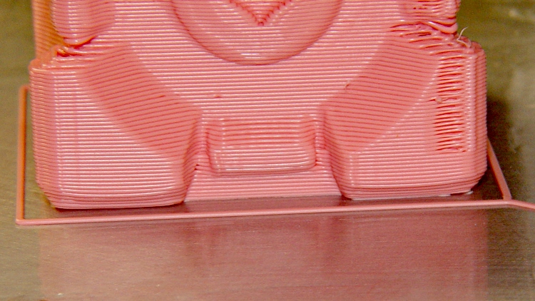
    Companion cube, with a slightly warped right corner:

    Companion Cube - build detail
    Companion Cube – build detail

    Now, those objects may have other problems, but two things work really well:

    • The first layer sticks like it was glued to the ABS film
    • The side walls build perfectly straight, without bulges or shrinkage

    What’s important to me: this is dependable and repeatable.

    It’s not yet a simple routine, because these objects were built while I was hacking away at the HBP + aluminum plate platform, some are on the old ABP + aluminum plate arrangement, and they’re not all first-attempt parts. However, given a proper setup, It. Just. Works.

    Part of the process involves a very slow first-layer feed: about 10 mm/s. At that pace the molten ABS has enough time to bond with the layer on the plate, even around corners; much faster and it can pull free.

    The Extruder runs at 210 °C, the HBP at 120 °C, feed is 40 mm/s, and traverse is around 50 mm/s.

    It is yet to be seen if this lashup will remain stable, but the first indications seem pretty good.

  • Monitoring Build Plate Leveling with the Outline Extrusion

    The Skeinforge Outline plugin draws a rectangle around the first perimeter layer of an object. I use that single-width, single-layer extrusion to monitor the height of the nozzle above the build platform and the tilt of the plate. The Outline extrusion will either peel off separately or come off as the film peels away from the plate when I twist the object off.

    These Outlines come from a variety of objects. The one in the lower left was a test case that I stopped after extruding only the Outline.

    ABS coatings from aluminum build plates
    ABS coatings from aluminum build plates

    I measure the Outline along each edge; larger objects provide three data points along each side of the build platform.

    The good part of this is that it reports the build platform’s behavior during an actual extrusion, so you can keep an eye on whether it’s drifting out of alignment. The aluminum plates present a sufficiently flat surface that any variations will be due to a non-level HBP or an off-calibration Z-axis.

    These numbers from around a large Outline told me that I should tweak the Z axis height down by 0.1 mm to increase the first layer thickness back to about 0.33 mm. The lower-right corner was slightly thicker because the wiper hit the Thermal Core insulation.

    0.24 0.22 0.17
    0.27 0.17
    0.27 0.22
    0.28 0.32
    0.22 0.21 0.24

    Given those values, I can tweak the leveling screws to adjust the platform tilt. What I don’t have at this point is any long-term record of how consistent my hacked HBP will be. But at least I’ve got numbers!

  • Un-milling Some Slots

    The first aluminum build plates had to fit around the gimcrackery atop my tweaked ABP: two solderless grounding lugs and a lump of Wire Glue. The new HBP setup put the grounding lug below the fixed plate and did away with the lump, so the removable plate could have five holes and a wiper cutout without any fancy trimming.

    I’d squared up three plates and machined only two for the ABP, so I had one plate that just needed drilling. Rather than machining two new plates, I filled the cutouts on the old plates with JB Industro Weld epoxy, flycut the excess, and drilled new holes.

    Flycut and drilled epoxy fill
    Flycut and drilled epoxy fill

    This was straightforward manual CNC: get the plate square on the table, touch off the plate edges, and then drill the holes in two steps.

    If those thin epoxy webs break off the outside of the holes, it’s not the end of the world: the plates won’t go anywhere because they’re indexed by the holes on the other side.

    Memo to Self: Next time, make a fixture to hold the plates relative to a starting hole and eliminate all the tedious alignment steps.

  • Microscope LED Ring Illuminator

    A batch of LED ring lights arrived from halfway around the planet and I’d earmarked one for a microscope ring illuminator, despite the crappy color spectrum of white LEDs. It’s better than the fluorescent desk lamp I’d been using up to this point.

    This shows the business end of the LED ring light, which would probably look better more professional without the full-frontal Barbie color scheme:

    Microscope LED Ring light - snout view
    Microscope LED Ring light – snout view

    It’s less overwhelming from the top:

    Microscope with LED illuminator
    Microscope with LED illuminator

    The power cable came with the ring. I unsoldered it, fed the end through the shade, resoldered it, snipped off the automobile lamp adapter, wired it to a switch and a 12 V 200 mA wall wart, and hot-melt-glued the switch to the microscope. Yet another vampire load, alas.

    The two parts must be printed separately to eliminate any problem with overhang, as the finished widget would have vertical walls on both sides. I thought about support material, realized that would be a lot like work, and split the thing into two parts.

    LED ring light - mounting plate and shade
    LED ring light – mounting plate and shade

    The walls on the shade ring show the same backlash problem that cropped up there; I built these before tweaking the belts.

    The mounting plate screws into the microscope’s accessory thread:

    Microscope LED Ring Light - Mount Plate
    Microscope LED Ring Light – Mount Plate

    Admittedly, “screws into” may be an exaggeration: the mount is just a cylindrical feature slightly larger than the microscope’s minor thread diameter; it’s barely more than a snug friction fit. I clipped out four small sections to allow that ring to bend slightly as it engages the threads.

    A shade contains the LED ring and keeps direct light off the objective lenses. There’s a tiny hole on one side to let the power wires out:

    Microscope LED Ring Light - Shade
    Microscope LED Ring Light – Shade

    The two parts got glued together with the same ABS-in-MEK gunk that I apply to the aluminum build plate:

    Clamping LED ring light parts
    Clamping LED ring light parts

    I applied three blobs of hot-melt glue inside the shade, lined up the LED ring’s power wire with the exit hole, and smooshed it into place. Pause for a breath and it’s done!

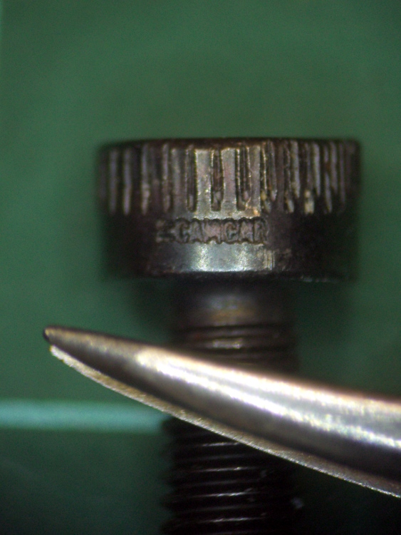
    The result actually looks pretty good, despite the weird yellow-and-blue spectrum you get free with every “white” LED. I reset the camera’s color correction using a white sheet of paper. This is an ordinary M3 socket head cap screw, familiar to Thing-O-Matic owners everywhere, and a tweaked needle-point tweezer:

    Sample image using LED ring light
    Sample image using LED ring light

    The microscope camera mount works surprisingly well, particularly given how simple it was to build.

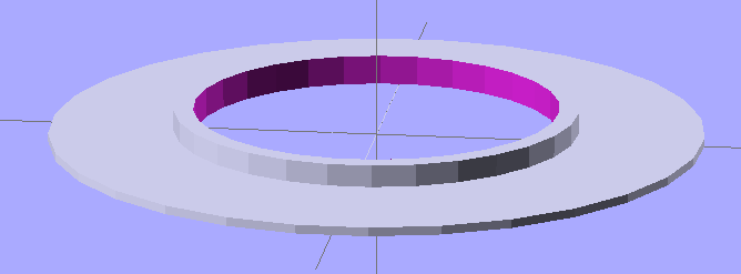
    The OpenSCAD source makes the shade walls a bit taller than you see above. When I run out of pink filament, this one’s on the rebuild list!

    // Microscope LED Ring Illuminator Mount
    // Ed Nisley - KE4ZNU - Mar 2011
    
    // Build with...
    //	extrusion parameters matching the values below
    //	2 extra shells
    //	3 solid surfaces at top + bottom
    
    Build = "Ring";					// Mount or Ring
    
    // Extrusion parameters for successful building
    
    ThreadZ = 0.33;						// should match extrusion thickness
    WT = 1.75;							// width over thickness
    ThreadWidth = ThreadZ * WT;			// should match extrusion width
    
    HoleWindage = ThreadWidth;			// enlarge hole dia by extrusion width
    
    // Screw mount dimensions
    
    MountOD = 46.85 - ThreadWidth;		// Microscope thread diameter (thread minor)
    MountDepth = 2.5;					// ... length
    MountID = MountOD - 6*ThreadWidth;	// ID of mount body -- must clear lenses
    
    echo(str("Mount ID: ",MountID));
    echo(str("Mount OD: ",MountOD));
    
    PlateThick = 3*ThreadZ;				// Thickness of mounting plate beyond rings
    
    echo(str("Plate: ",PlateThick));
    
    // LED Ring holder dimensions
    
    RingID = 54.0;
    RingOD = 71.0;
    RingFit = 0.5;						// radial gap from ID and OD
    
    InnerShade = 6.0;					// Shade walls around ring
    OuterShade = 10.0;
    ShadeWall = 4*ThreadWidth;			//  wall thickness
    
    HolderID = RingID - 2*RingFit - 2*ShadeWall;
    HolderOD = RingOD + 2*RingFit + 2*ShadeWall;
    
    echo(str("Holder ID:",HolderID));
    echo(str("Holder OD:",HolderOD));
    
    LeadWidth = 4.0 + HoleWindage;		// LED power lead hole
    LeadTall = 2.0 + HoleWindage;
    
    Protrusion = 0.1;					// extend holes beyond surfaces for visibility
    
    //---------------
    // Create thread gripper and plate
    
    module Mount() {
    
      difference() {
    	union() {
    	  translate([0,0,PlateThick])
    		cylinder(r=(MountOD/2 + HoleWindage),h=MountDepth);
    	  cylinder(r=HolderOD/2,h=PlateThick);
    	}
    
    	translate([0,0,-Protrusion])
    	  cylinder(r=MountID/2,h=(PlateThick + MountDepth + 2*Protrusion));
      }
    
    }
    
    //----------------
    // Create LED ring holder
    
    module Ring() {
    
      difference() {
    	union() {
    	  cylinder(r=HolderOD/2,h=PlateThick);
    
    	  translate([0,0,PlateThick]) {
    		difference() {
    		  cylinder(r=HolderOD/2,h=OuterShade);
    		  cylinder(r=(HolderOD/2 - ShadeWall),h=(OuterShade + Protrusion));
    		}
    
    		cylinder(r=(HolderID/2 + ShadeWall),h=InnerShade);
    	  }
    	}
    
    	translate([0,0,-Protrusion])
    	  cylinder(r=HolderID/2,h=(InnerShade + PlateThick + 2*Protrusion));
    
    	translate([(HolderOD/2 - ShadeWall/2),0,(PlateThick + ShadeWall/2 + LeadTall/2)]) {
    	  scale([ShadeWall*2,LeadWidth,LeadTall])
    		rotate(a=[0,90,0])
    		  cylinder(r=0.5,h=1.0,center=true,$fn=12);
    	}
      }
    
    }
    
    //---------------
    // Build what's needed
    
    if (Build == "Mount") {
      Mount();
    }
    else {
      Ring();
    }