The Smell of Molten Projects in the Morning

Ed Nisley's Blog: Shop notes, electronics, firmware, machinery, 3D printing, laser cuttery, and curiosities. Contents: 100% human thinking, 0% AI slop.

Tag: CNC

Making parts with mathematics

  • Pololu Stepper Driver Board Heatsinking: Crude Prototype

    Those cute little Pololu stepper driver boards using the Allegro A4988 chip have one conspicuous problem: there’s no good way to heatsink the chip. The doc recommends heatsinking for currents around 1 A and some informal testing shows it will trip out on thermal protect around 800 mA, so heatsinking really isn’t optional.

    A thermal pad from the chip bonds to vias that conduct heat through the PCB to the bottom surface copper layer: putting a heatsink on the top doesn’t help as much as one on the bottom. What I’m doing here is a first pass at a bulk heatsink that would work with several of the driver chips lined up in a row; this one is ugly and doesn’t work well, but it should let me do some further electrical tests.

    The general idea is to clamp the heatsink around the board, with the chip as the top-side pressure point. The catch: no room for an actual heatsink underneath, because that’s where the connector pins live. You could mount the board upside-down, but then there’s no good way to tweak the stepper current trimpot. That may not be a problem after you get things set up, although I’d hate to unplug and replug the board for each adjustment.

    So I think a reasonable solution involves a metal strip to conduct the heat out the ends and up to the heatsink. What I’ve done here does not accomplish that; I’m just feeling around the parameter space.

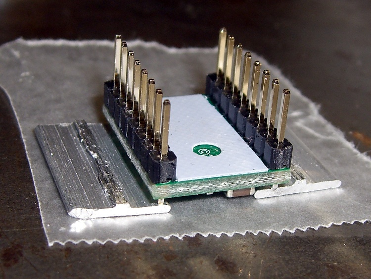
    You can’t get too enthusiastic with the clamping force, lest you crush the chip, so moderate pressure is the rule of the day. However, the chip sits low on the board, surrounded by taller components, so I put a drop of epoxy on top and flipped it over to produce a short thermally conductive column that’s higher than everything else:

    Pololu stepper board - epoxy curing
    Pololu stepper board – epoxy curing

    The blue sheet comes from a trimmed-down TO-220 transistor heatsink pad; it’s thermally conductive silicone, provides a bit of compliance against the PCB, and insulates the REF trimpot test point from the heatsink.

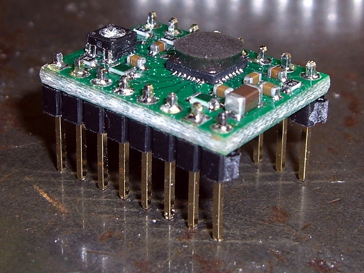
    The result looks OK, but it would be better to embed a small metal block between thinner epoxy layers to get better thermal conductivity:

    Pololu stepper board - epoxy blob on driver chip
    Pololu stepper board – epoxy blob on driver chip

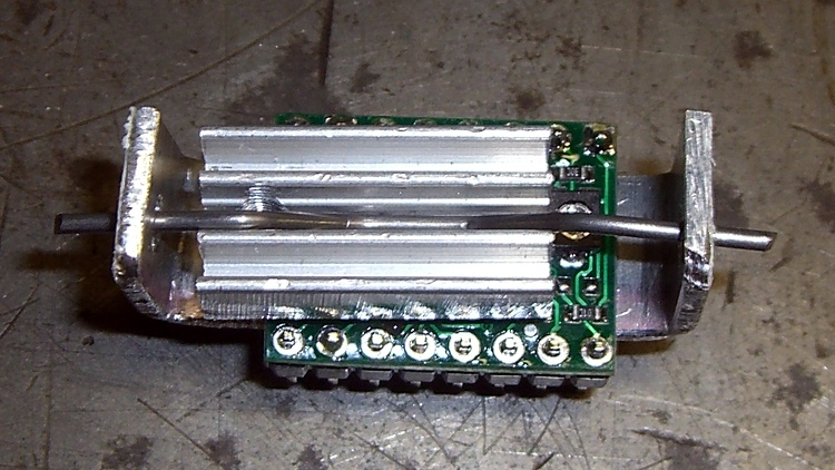
    Although most of the heat goes out the bottom, you still need something on the top to take the spring pressure. I trimmed down the TO-220 heatsink that came with that silicone pad; it must mount off-center to permit access to the trimpot but, alas, blocks the voltage monitoring pad and both sense resistors. A length of 45-mil music wire bent into a flat M  provides the spring:

    Pololu stepper board - heatsink top view
    Pololu stepper board – heatsink top view

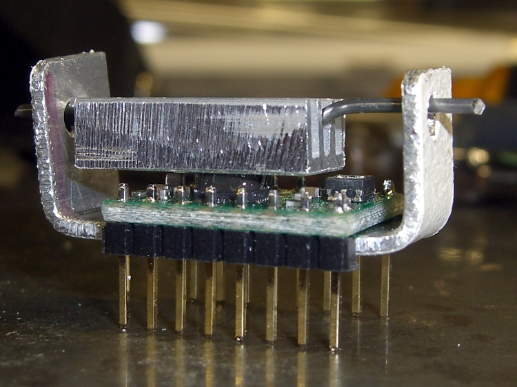
    The side view show how the kludge fits together:

    Pololu stepper board - crude heatsink
    Pololu stepper board – crude heatsink

    The final result is truly ugly. The epoxy column didn’t turn out nearly as parallel to the PCB as I’d like, so some filing and finishing will be in order.

    Now, to find out if it’ll allow the chip to run above 1 A for at least a while.

  • Stepper Motor Oscillocope Synchronization: Arduino to the Rescue!

    In order to get good scope pictures of the winding current in a stepper motor, the scope must sync to the step pulses. However, it must also sync to the groups of 32 step pulses that make up a single set of four full steps, because the winding current repeats for each of those groups. Triggering once per revolution and delaying for a fixed amount will get you where you need to be.

    The sync wheel provides a once-per-revolution pulse, but there’s some jitter in the edge for all the usual reasons and you’d be better off with a sync based on the stepper driver’s step input. The general idea is to find the leading edge of the optical pulse, find the next step pulse, then produce output pulses based on the step signal. Assuming a regular step pulse stream (from a pulse generator, for example), the output will be both locked to the wheel rotation and to the step pulses.

    Normally this calls for a tedious wiring session involving logic gates and counters, but an Arduino has all the requisite machinery built in. The trick is to generate the pulses using the ATmega’s hardware, rather than program instructions, thus eliminating the usual jitter caused by instruction execution time.

    I set up Timer 1 in Mode 4 (CTC with OCR1A controlling the matches) to count step pulse inputs on its T1 external clock input pin and produce a once-per-revolution output pulse on the OC1A pin. Because the output changes on the rising edge of the input clock, its rising and falling edges will provide rock-solid stable scope synchronization.

    The big picture goes a little something like this:

    • Tell the counter to set the output on match, load the duration of the output pulse
    • Wait for the once-per-revolution signal, then enable the external clock input
    • Wait for the comparison to happen and reset the match flag
    • Set a one-pulse delay and tell set the counter to clear the output on match
    • Wait for the compare, clear the flag, turn off the counter
    • Wait until the once-per-rev signal goes low
    • And then do it all over again

    Which produces this:

    Sync Wheel
    Sync Wheel

    Top trace = optical signal from interrupter, middle = 1/rev sync from Arduino OC1A pin, bottom = step pulses. The motor is turning 3.5 rev/s = 210 rev/min. The top half of the screen is at 2 ms/div, the bottom half at 200 μs/div.

    You could synchronize the counter to the 1/rev input exactly once, then produce the output pulse just by counting stepper pulses. It’d also be nice to have a pulse that repeats for each group of 32 microsteps within each set of four full steps, perhaps settable to a particular microstep within the group. All that’s in the nature of fine tuning.

    Of course, devoting an Arduino to this project would be absurd, but for a one-off effort it makes a lot of sense.

    The Arduino source code:

    // Stepper motor driver synchronization
    // Ed Nisley KE4ZNU June 2011
    
    //-- Pin definitions, all of which depend on internal hardware: do *not* change
    
    #define PIN_REV	2					// INT0 = positive 1/rev pulse from optical switch
    #define PIN_STEP 5					// T1 = positive 1/step pulse from stepper driver
    #define PIN_TRIGGER 9				// OC1A = positive trigger pulse to scope
    
    #define SYNC_OFFSET	15				// steps from 1/rev puse to start of first 4-full-step group
    
    #define PIN_TRACE_A    10
    #define PIN_TRACE_B    11
    #define PIN_TRACE_C    12
    
    #define PIN_LED		13
    
    //---------------------
    // Useful routines
    
    //--- Input & output pins
    
    void TogglePin(char bitpin) {
    	digitalWrite(bitpin,!digitalRead(bitpin));    // toggle the bit based on previous output
    }
    
    //----------------
    // Initializations
    
    void setup() {
    
      pinMode(PIN_REV,INPUT);		// INT0 1/rev pulse from wheel
    
      pinMode(PIN_STEP,INPUT);		// T1 step pulse from stepper driver
    
      pinMode(PIN_LED,OUTPUT);
      digitalWrite(PIN_LED,LOW);
    
      pinMode(PIN_TRACE_A,OUTPUT);
      pinMode(PIN_TRACE_B,OUTPUT);
      pinMode(PIN_TRACE_C,OUTPUT);
    
    //--- Prepare Timer1 to count external stepper drive pulses
    
      TCCR1B = B00001000;				// Timer1: Mode 4 = CTC, TOP = OCR1A, clock stopped
    
      pinMode(PIN_TRIGGER,OUTPUT);		// OC1A to scope trigger
    
    }
    
    //----------------
    // The main event
    
    void loop() {
    
    //-- Wait for rising edge of 1/rev pulse from optical switch
    
      TCCR1A = B11000000;						// COM1A set on compare
      TCNT1 = 0;								// ensure we start from zero
      OCR1A = SYNC_OFFSET;						// set step counter
    
      while(!digitalRead(PIN_REV)) {			// stall until 1/rev input rises
    	TogglePin(PIN_TRACE_A);
      }
    
    //-- Got it, fire up the timer to count stepper driver pulses
    
      TCCR1B |= B00000111;						// enable clock from T1 pin, rising edge
    
      digitalWrite(PIN_LED,HIGH);				// show we got here
      digitalWrite(PIN_TRACE_A,LOW);
    
      while(!(TIFR1 & _BV(OCF1A))) {			// wait for compare
    	digitalWrite(PIN_TRACE_B,digitalRead(PIN_STEP));
    	continue;
      }
      TIFR1 |= _BV(OCF1A);						// clear match flag
    
    //-- Scope sync pulse now active
    
      digitalWrite(PIN_LED,LOW);				// show we got here
      digitalWrite(PIN_TRACE_B,LOW);
    
    //-- Wait for another step pulse to clear scope sync
    
      TCCR1A = B10000000;						// COM1A clear on compare
      OCR1A = 1;								// wait for another pulse
    
      while(!(TIFR1 & _BV(OCF1A))) {			// wait for compare
    	digitalWrite(PIN_TRACE_B,digitalRead(PIN_STEP));
    	continue;
      }
      TIFR1 |= _BV(OCF1A);						// clear match flag
      digitalWrite(PIN_TRACE_B,LOW);
    
    //-- Shut down counter and wait for end of 1/rev pulse
    
      TCCR1B &= ~B00000111;						// turn off timer clock
    
      while(digitalRead(PIN_REV)) {				// stall until 1/rev pulse goes low again
    	TogglePin(PIN_TRACE_C);
      }
      digitalWrite(PIN_TRACE_B,LOW);
    
    }
    
  • Stepper Motor Sync Wheel

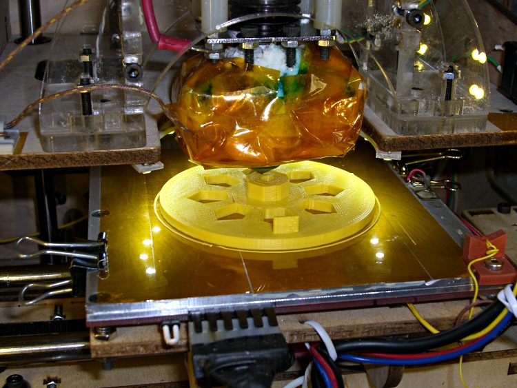
    A need for pix of the current waveforms in a stepper motor produced a need to synchronize to the shaft rotation. Rather than cobble something up using random spare parts, I printed a wheel with a tab:

    Final rotation sync disk
    Final rotation sync disk

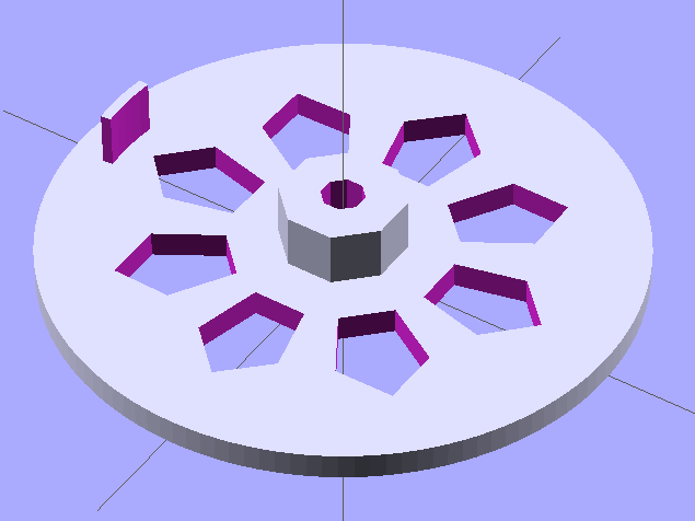
    The model looks about like you’d expect:

    Synch wheel solid model
    Synch wheel solid model

    Those stretched pentagonal holes give it a vaguely religious aspect, don’t they?

    The tab is 2/50 of the circumference, so that the resulting pulse neatly brackets two consecutive groups of four full-step pulses. There’s no way to align the tab with the rotor position, so producing a good scope sync pulse becomes a simple matter of software.

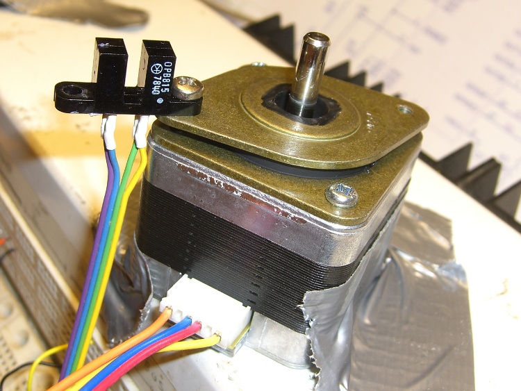
    The tab’s length and radial position corresponds to this carefully engineered bit of mayhem:

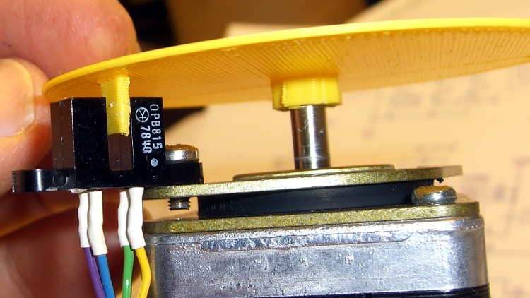
    Optical interrupter on stepper isolator bushing
    Optical interrupter on stepper isolator bushing

    The shaft hole will be just slightly too small for the motor shaft, which is perfectly fine. Drill the hole to 5 mm using a #9 drill, working your way up from about #12 to keep the hole concentric.

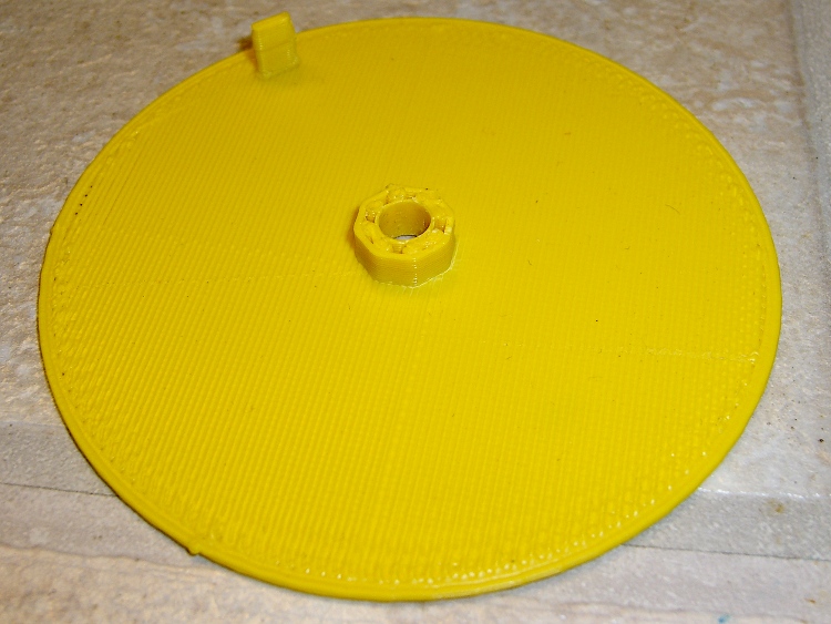
    Actually, that was the second version. The first was a quick-and-dirty disk with a tab, but it came out too floppy at only 1 mm thick and utterly boring:

    Simple rotation sync disk
    Simple rotation sync disk

    But it served as the prototype to settle the tab dimensions and location:

    First synch disk with optical interrupter
    First synch disk with optical interrupter

    The OpenSCAD source:

    // Optical Interrupter
    // Suited for low speed demonstrations!
    // Ed Nisley KE4ZNU June 2011
    
    //- Extrusion parameters - must match reality!
    //  Print with +2 shells and 3 solid layers
    
    ThreadThick = 0.33;
    ThreadWidth = 2.0 * ThreadThick;
    
    //- Plate dimensions
    
    MotorShaftDia = 5.0;
    MotorShaftDiaSides = 8;
    MotorShaftPolyRadius = (MotorShaftDia/2)/cos(180/MotorShaftDiaSides);
    
    HubDia = MotorShaftDia + 16*ThreadWidth;
    HubThick = ceil(10.0/ThreadThick)*ThreadThick;		// total, not added to plate
    HubSides = 8;
    
    BladeRadius = 31.5;				// to center of optical switch gap
    BladeThick = 2*ThreadWidth;		// measured radially
    BladeAngle = (2/50)*360;		// 50 repeats of 4 full step sequences per rev
    BladeHeight = 7.0;				// beyond ribs
    
    PlateRadius = BladeRadius + 5.0;
    PlateThick = ceil(3.0/ThreadThick) * ThreadThick;
    
    HoleCenterRad = (BladeRadius + HubDia/2)/2;
    HoleDia = 0.75 * (3.14159 * 2 * HoleCenterRad)/HubSides;
    HoleSides = 5;
    
    //- Convenience items
    
    Protrusion = 0.1;
    $fn = 128;						// make large circles very smooth
    
    //- Build it!
    
    difference() {
      union() {
    	cylinder(r=PlateRadius,h=PlateThick);			// base plate
    
    	cylinder(r=HubDia/2,h=HubThick,$fn=HubSides);	// hub
    
    	translate([0,0,PlateThick])						// blade
    	  difference() {
    		cylinder(r=BladeRadius+BladeThick/2,h=BladeHeight);
    		cylinder(r=BladeRadius-BladeThick/2,h=BladeHeight + Protrusion);
    		rotate([0,0,(180 - BladeAngle/2)])
    		  translate([PlateRadius,0,(BladeHeight + Protrusion)/2])
    			cube([PlateRadius*2,PlateRadius*2,BladeHeight+Protrusion],center=true);
    		rotate([0,0,(BladeAngle/2)])
    		  translate([PlateRadius,0,(BladeHeight + Protrusion)/2])
    			cube([PlateRadius*2,PlateRadius*2,BladeHeight+Protrusion],center=true);
    	  }
    
      }
    
      translate([0,0,-Protrusion])						// shaft hole
    	cylinder(r=MotorShaftPolyRadius,
    			 h=HubThick+2*Protrusion,
    			 $fn=MotorShaftDiaSides);
    
      for (Angle = [0:(HubSides-1)])					// beautification holes
    	rotate([0,0,Angle*(360/HubSides)])
    	  translate([HoleCenterRad,0,-Protrusion])
    		rotate([0,0,180])
    		  scale([1.33,1.0,1.0])
    			cylinder(r=HoleDia/2,
    					 h=(PlateThick + 2*Protrusion),
    					 $fn=HoleSides);
    
    }
    

    Yeah, that optical switch really is older than you are…

  • Why Manual CNC Is A Bad Idea

    Crushed tool length probe switch
    Crushed tool length probe switch

    Most of my machining involves one-off setups and simple cuts, so I usually type G-Code directly into EMC2’s Axis interface: CNC hits precise locations and makes smoother cuts than I ever could. Most of the time, that works really well.

    Occasionally, though, I think one thing and type something else.

    Just a typo, happens all the time…

    Better, of course, to write a little program and debug it, but then a simple task starts to look a lot like work.

    Fortunately, I have a bunch of those switches on hand.

  • Thing-O-Matic: Work Flow

    The reason I didn’t see the yellow low-overheat LED blink on when the Thermal Core ran away was that I’m usually upstairs except when actually printing.

    My modus operandi involves sitting at my upstairs desk, fiddling with an OpenSCAD solid model until I like it, then exporting the STL file. This PC has larger screens, better graphics hardware, a fast CPU, a Comfy Chair, and ready access to the kitchen.

    The Thing-O-Matic lives in the Basement Laboratory, connected to a dual-core Atom D520 PC running Ubuntu 10.04 LTS with ReplicatorG to control the printer. That PC dual-boots into the RTAI-patched kernel that runs EMC2 for the Sherline mill and is firmly cabled to the Sherline driver box. That PC’s monitor is up on the wall, the chair is a modified lab stool, and the miniature keyboard is barely suited for hunt-and-poke controls. Not a good place to sit and type.

    That PC also has a USB webcam showing an interior view of the printer. I run XawTV, a minimal video capture program, to put that view on the PC’s desktop. I could set it up as a webserver camera, but that seems like too much work.

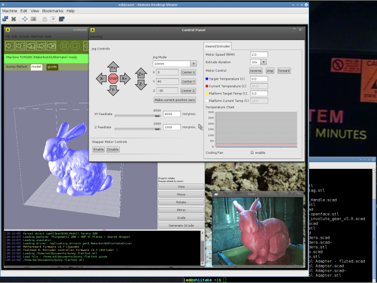
    I use the Ubuntu desktop-sharing program to view / control the downstairs programs in a window on my (larger) upstairs monitor, so I can fiddle with RepG from the Comfy Chair. There’s a moderate lag due to stuffing the GUI through the network, but it’s tolerable for small changes & tweaks. The webcam view occupies one corner of the screen.

    This is a staged reenactment showing the remote “downstairs” desktop in the left, with the “upstairs” desktop visible to the right:

    Remote Desktop Screenshot - lowres
    Remote Desktop Screenshot – lowres

    All the files live on our simpleminded server, which sits in the Basement Laboratory’s Computer Wing, and the PCs mount NFS shares from the server. I do all the bulk text editing & file fiddling from the Comfy Chair.

    So I save the STL file from the upstairs PC, flip to the window showing the downstairs machine’s desktop, copy the STL to a local drive to avoid lag during operation, run RepG to open the STL and slice it into G-Code, fire the Thing-O-Matic, and trot downstairs to watch the proceedings.

    As a rule, I don’t run the printer unattended, but now it looks like it’s a Bad Idea to run the heaters without being nearby. You knew that already, right?

  • Thing-O-Matic: Platform Height Consistency vs. Build Plates

    After building a bunch of stuff (about which more later), the Skirt extrusions showed a consistent tilt of about 0.1 mm downward to the right and the Skirt along the that side was consistently around 0.42 mm thick. So I cranked the right side down by 0.10 mm (just over 1/6 turn) and changed the G92 setting to Z1.50 to move the plate up by 0.05 mm.

    Three test extrusions in quick succession gave these results (in multiples of 0.01 mm). I used the plates in reverse numerical sequence due to an accident of history:

    Plate 3 36 31
    38 34 35 31
    36 38 36 34
    33 37
    Plate 2 37 33
    40 36 41 34
    37 37 36 37
    34 36
    Plate 1 33 31
    35 32 35 33
    33 33 33 36
    31 34

    It just won’t get any better than that!

  • Thing-O-Matic: Z-Minimum Probe G-Code

    The G-Code in start.gcode homes all three axes, but now I have two limit switches on the Z axis: the MBI Z-Maximum at the top and a new Z-Minimum on the platform. The Z axis platform can’t miss the switch at the top, but I must position the nozzle directly over the Z-Minimum switch on the platform before probing for it. Homing the stage at the top of the Z axis makes sure the nozzle starts more-or-less at the right height over the switch, which then provides an exact adjustment.

    For the home switches on my Sherline CNC milling machine, the EMC2 homing routines proceed in two stages: a fast slew to find the switch, then a slow approach to ensure the axis doesn’t overrun the switch. That seemed like a good way to ensure that the X and Y stages would home repeatably enough to hit a 2 mm button with a 1 mm nozzle every time.

    I recycled the default home sequence for coarse homing, albeit with the speeds cranked up a bit:

    (- coarse home axes -)
    G162 Z F1000	(home Z to get nozzle out of danger zone)
    G161 Y F4000	(retract Y to get X out of front opening)
    G161 X F4000	(now safe to home X)
    G92 X-53.0 Y-59.0 Z117.0	(set XYZ coordinate zeros)
    

    Then the fine homing sequence backs off a few millimeters and bumps the switches very slowly:

    (- fine home axes)
    G0 X-51 Y-57 Z115 F400	(back off switches)
    G161 Y F200
    G161 X F200
    G162 Z F200
    G92 X-53.0 Y-59.0 Z117.0	(re-set XYZ coordinate zeros)
    

    You could set relative motion mode with G91; that might be cleaner all around.

    I discovered experimentally that you must set all three axes in the G92 command, because any missing axes get set to 0.0: probably not what you want. It’s not what I expected, either, but this isn’t the EMC2 G-Code dialect I’m more familiar with.

    In normal use, the extruder has been heating for quite a while and there’s no pressure inside. There’s most likely a long strand of filament hanging off the end that will interfere with the switch, so a preliminary wipe is in order. I first pause the nozzle over the middle of the platform as a visual indication that everything started up OK, then make a dogleg around the wiper blade to the front of the wipe station:

    (- manual nozzle wipe)
    G0 X0 Y0 Z10	    (pause at center to build confidence)
    G4 P500
    G0 X40 Y-57.0 Z10	(move to front, avoid wiper blade)
    G0 X56            (to wipe station)
    G0 Z6.0           (down to wipe level)
    M6 T0			        (wait for temperature settling)
    G1 Y-40	F1000		  (slowly wipe nozzle)
    

    With the dry wipe done, move to the Z-Min switch and poke it very very slowly:

    (- home Z downward to platform switch)
    G0 X55.9 Y8 Z3	      (get over build platform switch)
    G161 Z0 F50	          (home downward very slowly)
    G92 X55.7 Y8 Z1.45	  (set Z for actual switch trip height)
    G0 Z6.0			          (back off switch to wipe level)
    

    I had to determine the actual height of the trip point experimentally, by doing some test extrusions and adjusting that Z1.45 to make the answer come out right. I’m sure that will change as things settle into their final places.

    Ditto for the exact XY location of the Z-Min switch, which I found by using a very slow G1 move to Z2.0 in place of the G161 probe.

    Note that you increase the Z value in G92 to lower the initial nozzle position and vice versa. It helps to draw some diagrams and work through the whole thing to be sure you understand it; that’s what I had to do, anyway.

    Then return the nozzle to the wipe station by running over the blade again to dislodge any gunk on the front side, crank up the extruder to build up pressure, and wipe again to get rid of the snot ball:

    (- start extruder and re-wipe)
    G0 X56 Y-40     (set up for wipe from rear)
    G1 Y-57.0 F1000 (wipe to front)
    M108 R2.0	      (set stepper extruder speed)
    M101		        (Extruder on, forward)
    G4 P4000  	    (take up slack, get pressure)
    M103		        (Extruder off)
    G4 P4000  	    (Wait for filament to stop oozing)
    G1 Y-40	F1000		(slowly wipe nozzle again)
    G0 X0           (get away from wiper blade)
    

    Running the extruder here ensures that, no matter what, the molten ABS in the hot end begins the print in a consistent state every time. The extruded length varies from a few millimeters to a real string, so there’s obviously plenty of variation.

    Then I put a manual splodge turd at the middle of the front edge of the platform. This is unnecessary now that SF40 shuts off the extruder before zipping off to the first Skirt, so I’ll probably junk it in the near future:

    (- manual splodge)
    G0 X0 Y-58		  (to front center)
    G0 Z0.5 		    (just over surface)
    M108 R2.0	      (set stepper extruder speed)
    M101            (start extruder)
    G4 P2000        (build up a turd)
    

    Putting all that together with some odds & ends gives the complete current version of start.gcode:

    (---- start.gcode begins ----)
    (MakerBot Thing-O-Matic with aluminum HBP and Z-min platform switch)
    (Tweaked for TOM 286 - Ruttmeister MK5 stepper extruder mod)
    (Ed Nisley - KE4ZNU - May 2011)
    (- set initial conditions -)
    G21		(set units to mm)
    G90		(set positioning to absolute)
    (- begin heating -)
    M104 S210 T0	(extruder head)
    M109 S120 T0	(HBP)
    (- coarse home axes -)
    G162 Z F1000	(home Z to get nozzle out of danger zone)
    G161 Y F4000	(retract Y to get X out of front opening)
    G161 X F4000	(now safe to home X)
    G92 X-53.0 Y-59.0 Z117.0	(set XYZ coordinate zeros)
    (- fine home axes)
    G0 X-51 Y-57 Z115 F400	(back off switches)
    G161 Y F200
    G161 X F200
    G162 Z F200
    G92 X-53.0 Y-59.0 Z117.0	(re-set XYZ coordinate zeros)
    (- manual nozzle wipe)
    G0 X0 Y0 Z10	    (pause at center to build confidence)
    G4 P500
    G0 X40 Y-57.0 Z10	(move to front, avoid wiper blade)
    G0 X56            (to wipe station)
    G0 Z6.0           (down to wipe level)
    M6 T0			        (wait for temperature settling)
    G1 Y-40	F1000		  (slowly wipe nozzle)
    (- home Z downward to platform switch)
    G0 X55.9 Y8 Z3	      (get over build platform switch)
    G161 Z0 F50	          (home downward very slowly)
    G92 X55.7 Y8 Z1.45	  (set Z for actual switch trip height)
    G0 Z6.0			          (back off switch to wipe level)
    (- start extruder and re-wipe)
    G0 X56 Y-40     (set up for wipe from rear)
    G1 Y-57.0 F1000 (wipe to front)
    M108 R2.0	      (set stepper extruder speed)
    M101		        (Extruder on, forward)
    G4 P4000  	    (take up slack, get pressure)
    M103		        (Extruder off)
    G4 P4000  	    (Wait for filament to stop oozing)
    G1 Y-40	F1000		(slowly wipe nozzle again)
    G0 X0           (get away from wiper blade)
    (- manual splodge)
    G0 X0 Y-58		  (to front center)
    G0 Z0.5 		    (just over surface)
    M108 R2.0	      (set stepper extruder speed)
    M101            (start extruder)
    G4 P2000        (build up a turd)
    (---- start.gcode ends ----)
    

    Then I did a bunch of measurements to see how it worked…