The Smell of Molten Projects in the Morning

Ed Nisley's Blog: Shop notes, electronics, firmware, machinery, 3D printing, laser cuttery, and curiosities. Contents: 100% human thinking, 0% AI slop.

Tag: CNC

Making parts with mathematics

  • Building an LED Floodlight Into a Task Lamp

    Building an LED Floodlight Into a Task Lamp

    LED Gooseneck Floodlight
    LED Gooseneck Floodlight

    Eks forced me to take a pile of crap useful make-froms, including a gooseneck task lamp that was probably bolted onto a machine tool in its former life. It sported a 20 W halogen bulb, but looked to be just about exactly the right size for those LED floodlights, which is why I didn’t put up much of a fuss about taking it off his hands.

    The LED lamps are much bigger than the halogen bulb, but they fit neatly into the housing diameter. All they needed was a bit more front-to-back room, which looked a lot like a chunk of PVC pipe. The housing screws together with a 1.5 mm thread that I can’t produce on my inch lathe; I’m still not set up for thread milling. This being a low-stress application with a lamp that ought to outlast me, I figured I’d just make the belly band slip-fit the two threads, glue it in place, and move on.

    I sawed off a length of PVC pipe, faced off the ends in the lathe, then CNC milled a recess to clear the male threads on the gooseneck part (I hate precision boring in the lathe). Given the rather tenuous grasp of that 3-jaw chuck, I made two passes around the perimeter: pipe ID 52.1, thread OD 54.5, remove 1.2 mm all around, about 9 mm down.
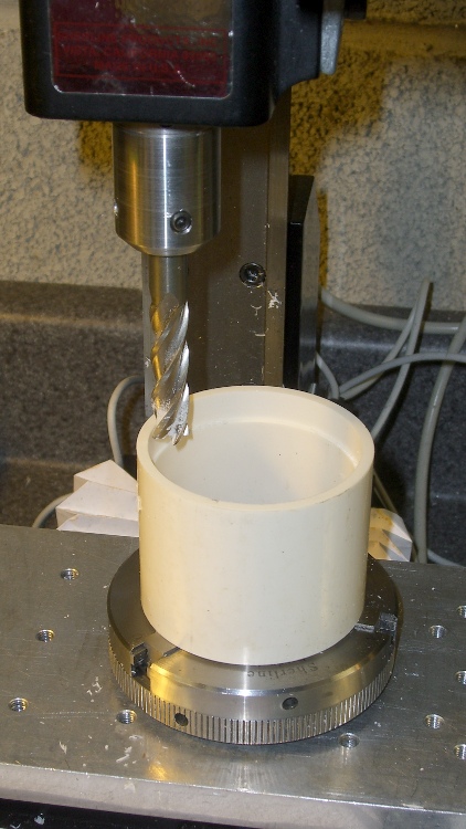
    Milling top recess
    Milling top recess

    On the other end, the female thread ID = 52.2 and the pipe ID = 52.1, so I glued another ring of PVC pipe inside to provide enough meat to turn it down. Once again, saw off a ring, face the ends, then cut out a segment so that the OD circumference of the inner ring is just slightly smaller than the ID circumference of the outer pipe. The result looked like this:
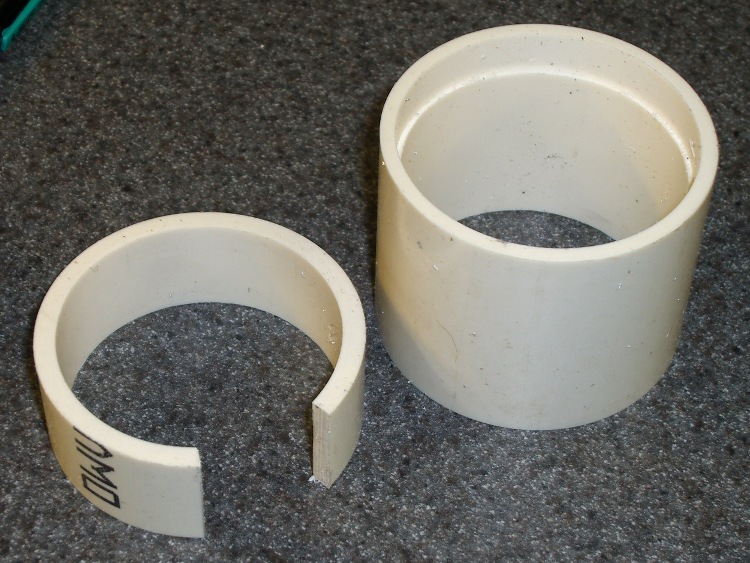
    PVC insert sizing
    PVC insert sizing

    Apply a heat gun to the inner ring until it’s soft enough to stuff into the pipe, clamp it until it hardens, apply PVC cement, and clamp overnight. Contrary to appearances, the ends of the two pipes are flush at the surface. Once again, you cannot have too many clamps:
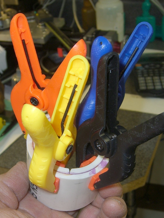
    Clamped PVC insert
    Clamped PVC insert

    Turning down the outside to fit the threads shows just how little meat was left on that pipe:
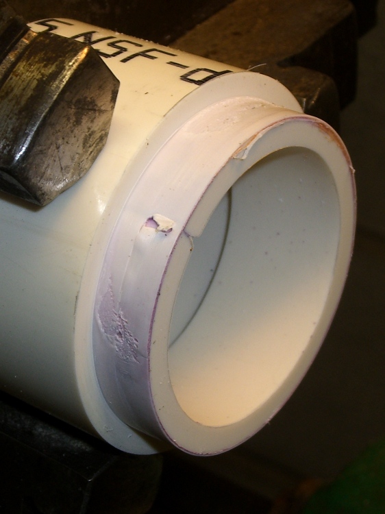
    Skinning down to the insert
    Skinning down to the insert

    While it was chucked up (and despite my dislike of boring) I bored a bevel to accept the LED lamp and adjusted the OD so the lamp fit snugly between the end of the belly band and the lens holder on the front of the housing:
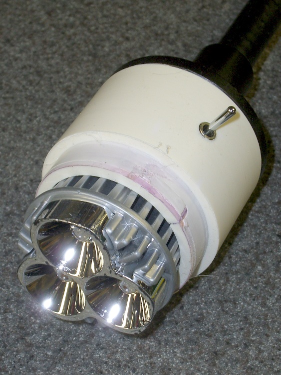
    Floodlight in holder
    Floodlight in holder

    The switch comes from the Parts Heap. A D drill puts a slightly undersized hole that’s just right for the threaded switch; I simply turned it in by hand. A length of zip cord carries the power up the gooseneck, where various ends get soldered to the switch and lamp.

    I applied some hot-melt glue to the threads and pushed everything together:
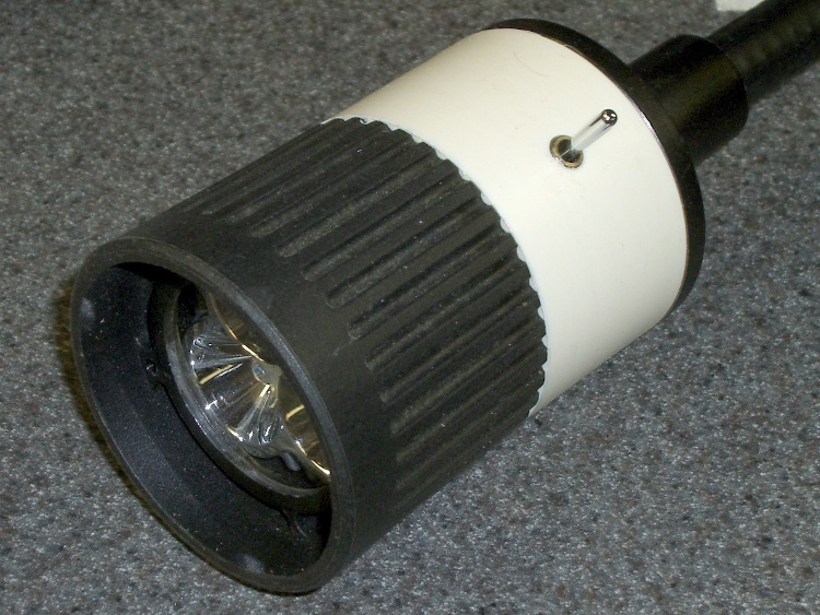
    Finished LED Floodlight
    Finished LED Floodlight

    The glass lens on the front fits in a molded holder with an annular air gap. The LED lamp housing has all those fancy cooling fins against the inner pipe, so there’s a bit of cooling air flow around the lamp and out through the rear black section. A thermocouple reports the lamp temperature gets up around 75 °C in a 14 °C shop; a 50 °C rise might be a tad warm in the summer, but we’ll see what happens.

    The power supply came from the Parts Heap: a 12 V 1 A wall switching power supply in the shape of a wall wart. For now, the zip cord from the lamp terminates in a coaxial power jack that (amazingly enough) fits the wart’s connector, but I’ll eventually put a box in there somewhere.

    Clamped the butt end of the gooseneck to the backsplash on the countertop under the mill and It Just Works!

  • Tour Easy: Zzipper Fairing Upper Mount Plates

    The stock Zzipper fairing handlebar mount consists of an aluminum bar with a plate welded to each end at more-or-less the correct angle to match the fairing curve. The plate has a 1/4 inch hole in one end, wherein a 1/4-20 nylon machine screw clamps the fairing to the plate, with a nylon washer distributing the stress. That doesn’t cope well with the vibrations caused by riding around here, let alone our summer vacation trips on crushed-stone rail trails, and the fairings tend to stress-crack at the holes.

    These 3D printed plates are just the latest in a long series of attempts to distribute the stress over a larger area. The outside view:

    Fairing mount - outside
    Fairing mount – outside

    The open hole gets another screw to hold the plates in position. The bump on the far side is an Oozebane turd, about which more later.

    The view from inside the fairing:

    Fairing mount - inside
    Fairing mount – inside

    You can’t see the layer of black foam rubber salvaged from a mouse pad between each plate and the fairing. That should prevent any local stress concentration at the screw and ease the transition to the tapered plate edges.

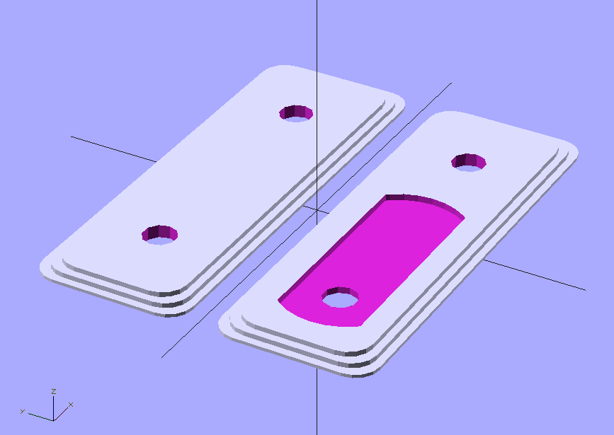
    The solid model looks about like you’d expect:

    Fairing Mount Plates - Upper
    Fairing Mount Plates – Upper

    The hole position depends on the fairing position, as the fairings have three holes. The pictures show the fairing on my bike; it’s in the lowest position, with the screw in the topmost hole. The OpenSCAD file has an option to put the holes where you need them.

    The plates are only 8 layers thick, printed with 4 solid layers top and bottom to eliminate any fill. You could do the same by setting the fill to 100%, I suppose. Using 4 outer shells (3 additional) makes the flanged edge nice and flat and uniform.

    The layer height is 0.33 mm, with w/t=1.7 for a width of 0.56 mm. Feed rate = 43 mm/s and flow rate = 255. DC Extruder, alas.

    Running the first layer at feed = 0.5  and flow = 0.75 produces some fluffing in the fill, but there’s no way to get a lower flow from the DC extruder motor. Flow = 0.75 corresponds to PWM=191; anything lower sometimes fails to start the motor. If it starts, it’ll run, but … that’s not dependable.

    I printed them on an aluminum plate for a nice flat bottom surface.

    The OpenSCAD source code:

    // Clamp plates for Zzipper fairing on Tour Easy recumbents
    // Ed Nisley - KE4ZNU - Mar 2011
    
    // Build with...
    //	extrusion parameters matching the values below
    //	4 outer shells
    //	4 solid surfaces at top + bottom
    //  slow feeds to ensure hole perimeters stick to fill
    
    include </home/ed/Thing-O-Matic/lib/MCAD/boxes.scad>
    include </home/ed/Thing-O-Matic/lib/MCAD/units.scad>
    
    // Select hole layout
    // The if statement seems to work only for CSG object trees
    // Fortunately, I need only two different layouts...
    
    HoleSelect = 1;						// 0 = his, 1 = hers
    
    HolesTop 	= (0 == HoleSelect) ? [0,1,1] : [1,0,1];
    HolesBottom = (0 == HoleSelect) ? [0,1,1] : [1,0,1];
    
    // Set these to match the extrusion parameters for successful building
    
    ThreadZ = 0.33;						// extrusion thickness
    ThreadWidth = 0.57;					// extrusion width = ThreadZ x w/t
    
    HoleWindage = ThreadWidth;			// enlarge hole dia by extrusion width
    
    // Plate dimensions
    
    HoleDia = 0.25 * inch;				// these are 1/4-20 bolt holes
    HoleSpace = (1) * inch;				// center-to-center spacing
    									//  usually 1 inch, but 15/16 on one bike
    
    CornerR = 5.0;						// corner rounding
    
    Layer1X = 90;						// against fairing surface
    Layer1Y = 32;
    Layer1Z = 2*ThreadZ;
    
    Layer2Margin = 1.5;					// uncovered edge
    Layer2X = Layer1X - 2*Layer2Margin;
    Layer2Y = Layer1Y - 2*Layer2Margin;
    Layer2Z = 3*ThreadZ;
    
    MountX = 46.3 + HoleWindage;		// handlebar mounting bracket end plate
    MountHoleSpace = 13.0;				//  end to hole center
    MountY = 16.3 + HoleWindage;
    MountZ = 4*ThreadZ;					// recess depth
    MountCap = 3.0;						// endcap arc height
    MountR = (pow(MountCap,2) + 0.25*pow(MountY,2)) / (2*MountCap);	// ... radius
    
    Layer3Margin = 1.5;
    Layer3X = Layer2X - 2*Layer3Margin;
    Layer3Y = max((Layer2Y - 2*Layer3Margin),(MountY + 8*ThreadWidth));
    Layer3Z = 3*ThreadZ;
    
    PlateZ = Layer1Z + Layer2Z + Layer3Z;
    
    // Convenience settings
    
    BuildOffset = 3.0 + Layer1Y/2;		// build Y spacing between top & bottom plates
    
    Protrusion = 0.1;					// extend holes beyond surfaces for visibility
    
    //---------------
    // Create plate with selectable holes
    
    module Plate(hs) {
    
      difference() {
    
    	union() {
    		translate([0,0,Layer1Z/2])
    		  roundedBox([Layer1X,Layer1Y,Layer1Z],CornerR,true);
    		translate([0,0,Layer1Z + Layer2Z/2])
    			roundedBox([Layer2X,Layer2Y,Layer2Z],CornerR,true);
    		translate([0,0,Layer1Z + Layer2Z + Layer3Z/2])
    			roundedBox([Layer3X,Layer3Y,Layer3Z],CornerR,true);
    	}
    
    	if (0 != hs[0]) {
    	  translate([-HoleSpace,0,PlateZ/2])
    		  cylinder(r=(HoleDia + HoleWindage)/2,
    					h=(PlateZ + 2*Protrusion),
    					center=true,$fn=10);
    	}
    
    	if (0 != hs[1]) {
    	  translate([0,0,PlateZ/2])
    		  cylinder(r=(HoleDia + HoleWindage)/2,
    					h=(PlateZ + 2*Protrusion),
    					center=true,$fn=10);
    	}
    
    	if (0 != hs[2]) {
    	  translate([HoleSpace,0,PlateZ/2])
    		  cylinder(r=(HoleDia + HoleWindage)/2,
    					h=(PlateZ + 2*Protrusion),
    					center=true,$fn=10);
    	}
    
      }
    
    }
    
    //---------------
    //-- Build the things...
    
    translate([0,BuildOffset,0]) Plate(HolesTop);
    
    translate([0,-BuildOffset,0])
      difference() {
    	Plate(HolesBottom);
    
    	translate([-(HoleSpace + MountHoleSpace - MountX/2),0,PlateZ - MountZ/2 + Protrusion/2])
    	  intersection() {
    		cube([MountX,MountY,(MountZ + Protrusion)],center=true);
    		union() {
    		  cube([(MountX - 2*MountCap),MountY,(MountZ + Protrusion)],center=true);
    		  translate([ (MountX/2 - MountR),0,0])
    			cylinder(r=MountR,h=(MountZ + Protrusion),center=true);
    		  translate([-(MountX/2 - MountR),0,0])
    			cylinder(r=MountR,h=(MountZ + Protrusion),center=true);
    		}
    	  }
      }
    

    I loves me my Thing-O-Matic, despite its annoyances…

    [Update: Stepper extruder parameters and a tweak to make the mount plate track the hole position correctly.]

  • 3D Printed Pactec Box Panel

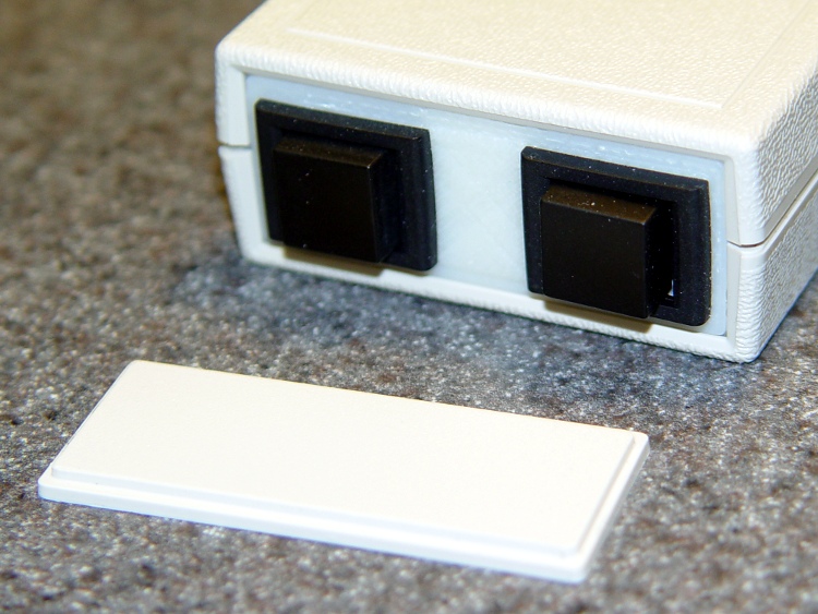
    As part of the Thermal Lockout project, I planned to put a pair of big pushbutton switches on the end of a little Pactec box, thusly:

    Pactec box - printed panel
    Pactec box – printed panel

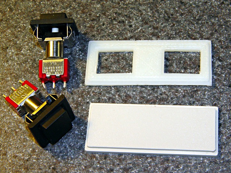
    I was in the midst of figuring out how to clamp that tiny panel to the Sherline milling machine’s table and gnaw out those big holes, when I realized I could just print out a new panel with the holes already in place:

    Pactec panels with switches
    Pactec panels with switches

    No muss, no fuss, no exciting chips… and no tedious corner filing, either.

    The 3D model has the hole for an LED that I added later; the panel shown above acquired that hole during a brief conference with Mr Drill Press.

    Thermal Cutout Box - switch plate model
    Thermal Cutout Box – switch plate model

    In actual point of fact, I had to do a bit of edge filing for the switches, as the holes came out slightly undersized. The HoleWindage setting should take care of that for the next time around. The panel was a drop-in replacement for the original: all the outside dimensions & thicknesses were spot on.

    The OpenSCAD source code:

    // End panel for PacTec 61191-01 box
    //    Panel 61580-01
    // Ed Nisley - KE4ZNU - Feb 2011
    
    Layer1Z = 1.50;
    Layer2Z = 1.00;
    
    HoleWindage = 0.55;                // approximately equal to extrusion width
    Protrusion = 0.1;                // stick out over top and bottom
    
    SwitchOffsetX = 15.0;
    
    SwitchX = 16.0 + HoleWindage;
    SwitchY = 12.0 + HoleWindage;
    SwitchZ = Layer1Z + Layer2Z;
    
    LedR = (5.0 + HoleWindage)/2;
    LedZ = SwitchZ;
    
    difference() {
     union() {
     translate([0,0,Layer1Z/2]) cube([55,22.5,Layer1Z],center=true);
     translate([0,0,(Layer1Z + Layer2Z)/2]) cube([52.6,19.5,Layer1Z + Layer2Z],center=true);
     }
    
     translate([SwitchOffsetX,0,SwitchZ/2])
     cube([SwitchX,SwitchY,SwitchZ + 2*Protrusion],center=true);
    
     translate([-SwitchOffsetX,0,SwitchZ/2])
     cube([SwitchX,SwitchY,SwitchZ + 2*Protrusion],center=true);
    
     translate([0,0,LedZ/2])
     cylinder(r=LedR,h=LedZ + 2*Protrusion,center=true,$fn=10);
    
    }
    
  • Sherline Collet Pusher Pin Holder

    Locking pin holder in use
    Locking pin holder in use

    Although that collet pusher works fine, the locking pin holder often teleported itself inside the vacuum cleaner. It recently reappeared on the far end of the main workbench, a good 15 feet away from the Sherline as the swarf flies. This, to misquote Churchill, is an impertinence up with which I shall not put.

    Herewith, a replacement offering several advantages:

    • Won’t fit up the vacuum’s snout
    • Easy to grip
    • Perfect pin alignment
    • 3D printing FTW!

    It’s a flat block resting on the flat top of the pulley, with a nice arc matching the pusher’s OD. A small hole for the pin at exactly the right altitude makes the whole thing rock-solid stable: it slides firmly into position.

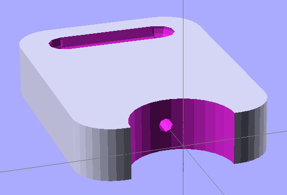
    The 3D model looks like you’d expect:

    Pin holder - OpenSCAD model
    Pin holder – OpenSCAD model

    The finger grips were just for pretty, as you don’t need that much traction to extract the thing.

    A similar view of the real object with the bottom surface up and some flash around the edges:

    Locking pin holder - spindle end view
    Locking pin holder – spindle end view

    The as-printed block put the pin about 0.2 mm above the spindle hole, so I rubbed it on Mr Belt Sander (with the power off) until it fit. I printed the block on the aluminum plate platform; the Z height home setting evidently needs a tweak. However, the hole was exactly the correct distance from the top surface: flipping the block over fit perfectly.

    The OpenSCAD source code:

    // Collet extractor locking pin holder for Sherline spindle
    // Ed Nisley - KE4ZNU - Feb 2011
    
    include </home/ed/Thing-O-Matic/lib/MCAD/boxes.scad>
    include </home/ed/Thing-O-Matic/lib/MCAD/units.scad>
    
    PusherOD = 17.35;					// Shell of collet pusher
    
    PulleyOD = 65.5;					// For 3k rpm head
    
    PinHoleCtr = (3/16) * inch;			// pin hole center above pulley surface
    PinDia = 2.50;						// pin is about #40 drill
    PinHoleDepth = 10.0;				// hole depth from PusherOD
    
    HoleWindage = 0.55;					// Approximate extrusion width
    Padding = 0.1;						// A bit of spacing to make things obvious
    
    HolderWidth = 2 * PusherOD;						// Overall holder width
    HolderProtrusion = 15;							// sticks out beyond pulley
    HolderLength = PulleyOD/2 + HolderProtrusion;	//	... length
    HolderThickness = 2*PinHoleCtr;					//	... thickness
    HolderRounding = HolderWidth/5;					// corner rounding
    
    GripLength = 0.70 * HolderWidth;	// grip notch
    GripWidth = 0.25 * GripLength;
    GripIndent = HolderProtrusion/2;
    
    difference() {
    
    // main slab
    
      translate([-HolderLength/2,0,0])
    	roundedBox([HolderLength,HolderWidth,HolderThickness],HolderRounding,true,$fn=4*8);
    
    // pin hole
    
      translate([-(PusherOD/2 + PinHoleDepth/2 - Padding),0,0])
      rotate([0,90,0])
    	cylinder(r=PinDia/2,h=(PinHoleDepth + Padding),center=true,$fn=8);
    
    // upper grip
    
      translate([-(HolderLength - GripIndent),0,(HolderThickness/2)])
      rotate([90,0,0])
    	cylinder(r=GripWidth/2,h=(GripLength - GripWidth),center=true);
    
      translate([-(HolderLength - GripIndent),((GripLength - GripWidth)/2),(HolderThickness/2)])
    	sphere(r=GripWidth/2,$fn=10);
    
      translate([-(HolderLength - GripIndent),-((GripLength - GripWidth)/2),(HolderThickness/2)])
    	sphere(r=GripWidth/2,$fn=10);
    
    // lower grip
    
      translate([-(HolderLength - GripIndent),0,-(HolderThickness/2)])
      rotate([90,0,0])
    	cylinder(r=GripWidth/2,h=(GripLength - GripWidth),center=true);
    
      translate([-(HolderLength - GripIndent),((GripLength - GripWidth)/2),-(HolderThickness/2)])
    	sphere(r=GripWidth/2,$fn=8);
    
      translate([-(HolderLength - GripIndent),-((GripLength - GripWidth)/2),-(HolderThickness/2)])
    	sphere(r=GripWidth/2,$fn=8);
    
    // spindle shaft
    
      cylinder(r=(PusherOD/2)+HoleWindage,h=(HolderThickness + 2*Padding),center=true);
    
    }
    
  • Thing-O-Matic: Measuring Build Plate Alignment

    The advantage of an aluminum build plate is that it’s flat, but it must also be parallel to the XY axis movements: the nozzle should have a constant altitude across the entire surface of the plate. There’s a tool for measuring that: a dial test indicator.

    Measuring build plate alignment
    Measuring build plate alignment

    I still don’t have solid way to mount the DTI to the Z axis stage, but the bar clamp works reasonably well. The DIT has a full-scale range of about 30 mils = 0.76 mm, with half on either size of the zero center point. Obviously the probe isn’t at right angles to the DTI body, but it’s close enough for differences of a few mils.

    The G-Code routine (see below) positions the Z stage in the middle of the platform and prompts you to mount the DTI and set the reading to 0.0. That requires a bit of delicate fiddling and anything within a few mils should be fine. Don’t adjust the leadscrew by hand, because all this depends on repeatable positioning.

    With that in place, the G-Code will raise the DTI, move the stage, lower the DTI, pause for five seconds while you note the reading, then repeat. For my DTI, the readings are in mils = 0.001 inch and, while I could record half-mil values, it’s not worth the effort.

    You’ll get nine numbers showing the height across the plate, spaced 20 mm in X and 25 mm in Y:

    0 3 6
    2 2 2
    1 -2 -4

    Subtract the minimum number from all the rest to remove the height offset and get everything referenced to zero:

    Minimum -4
    4 7 10
    6 6 6
    5 2 0

    Looks like the plate isn’t quite a planar surface (it’s bent!) and it tilts upward to the right rear, but the total difference amounts to 10 mils = 0.010 inch = 0.25 mm. I think that’s smaller than the variation caused by jitter and vibration and general creakiness in the X and Y stages. The repeatability seems to be within two or three mils, which is probably the limit of the hardware.

    Bottom line: good enough for now!

    The flat aluminum plate reveals a definite front-to-back bow in the heater plate. Clamping the two tightly together would fix that and improve heat transfer, but then the aluminum plate wouldn’t be easily removable when it’s hot.

    Put this G-Code routine (call it Flatness.gcode) in the ReplicatorG scripts/calibration directory and you’ll be able to run it from the menu:

    (Measure surface flatness)
    (MakerBot Thing-O-Matic with ABP and aluminum plate)
    (Tweaked for TOM 286)
    (Ed Nisley - KE4ZNU - Feb 2011)
    (-- The usual setup --)
    G21		(set units to mm)
    G90		(set positioning to absolute)
    (-- Home axes --)
    G162 Z F1500	(home Z to get nozzle out of danger zone)
    G161 Y F4000	(retract Y to get X out of front opening)
    G161 X F4000	(now safe to home X)
    (-- Set coordinate zeros --)
    G92 X-53.0 Y-58.0
    (G92 Z115.3)	(set Z for ABP with belt)
    G92 Z112.8	(set Z for ABP with aluminum sheet platform)
    (-- Get height gauge set up --)
    G0 X-10 Y10 Z25	(center gauge probe on platform)
    M1	(Attach gauge, set to 0.0 mm)
    G92 X0 Y0 Z0.0
    G0 Z2.0		(traverse height)
    (-- Begin probing --)
    G1 Z0.0		(denter)
    G4 P5000
    G0 Z2.0
    G0 X-40.0	(left center)
    G1 Z0.0
    G4 P5000
    G0 Z2.0
    G0 Y-50.0	(left front)
    G1 Z0.0
    G4 P5000
    G0 Z2.0
    G0 X0.0		(mid front)
    G1 Z0.0
    G4 P5000
    G0 Z2.0
    G0 X40.0	(right front)
    G1 Z0.0
    G4 P5000
    G0 Z2.0
    G0 Y0.0		(right center)
    G1 Z0.0
    G4 P5000
    G0 Z2.0
    G0 Y50.0	(right rear)
    G1 Z0.0
    G4 P5000
    G0 Z2.0
    G0 X0.0		(mid rear)
    G1 Z0.0
    G4 P5000
    G0 Z2.0
    G0 X-40.0	(left rear)
    G1 Z0.0
    G4 P5000
    G0 Z2.0
    G0 X0.0	Y0.0	(center again)
    G1 Z0.0
    G4 P5000
    (G0 Z5)
    
  • Thing-O-Matic: Aluminum Build Plate

    This is a variation of Thing 6384: an aluminum plate sitting atop the Automated Build Platform’s bare heat spreader, minus the belt. HIs truly ingenious idea was to cover the plate with a thin layer of ABS to ensure adhesion: an ABS filament bonds very well to ABS!

    Aluminum build plate in action
    Aluminum build plate in action

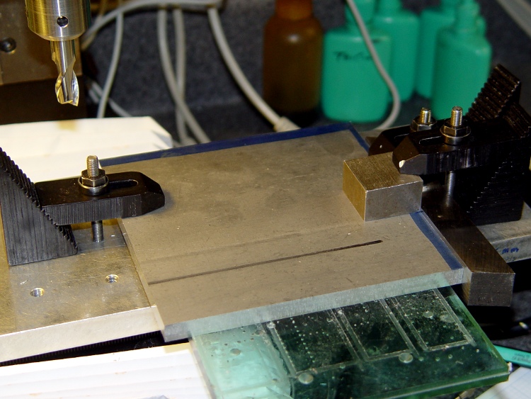
    I started with a big sheet of 3/32 inch aluminum, a bit thinner than the 1/8 inch sheet he used, which is what I had in the Parts Heap. Bandsawed three chunks to rough shape, squared up the edges on the Sherline with manual CNC:

    Squaring the sheets
    Squaring the sheets

    That was complicated by the Sherline’s cramped work envelope. The 5/8 inch lathe bit on the right sits at exactly right angles to the X axis and serves as the reference plane. To make it happen:

    • Stack the three plates, clamp to table aligned against lathe bit
    • Whack off the far edge
    • Put clean edge against lathe bit
    • Whack off another edge
    • Measure / scribe 120 mm from each new edge (thus the blue stripes)
    • Align & cut

    That actually worked quite well, although you’d think the angular error would build up as I rotated the plates. I checked and tweaked the angle after the first cut and it was all good.

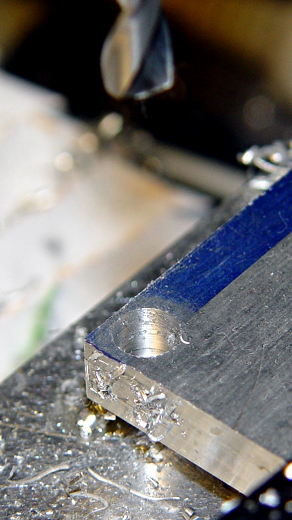
    Tight hole clearance
    Tight hole clearance

    Then drill six clearance holes for the socket head cap screws holding the heater plate to the ABP; a #1 drill gave a few mils clearance, which is all it needs. The holes are 4 mm in from the edges of the 120 mm square, with the two middle ones at, yes, 60 mm.

    However, there’s not much meat between the edge of the plate and the holes: call it 1.1 mm. If you do this, using 122 mm plates would produce less scary-close results. That’s why I like manual CNC for this stuff: no need to lay it out, tap in the numbers and it just Works.

    My APB heater has a static drain connected to the heat spreader, so I milled a 2 mm recess around the right-hand screws to clear the lugs, wires, and Wire Glue blob. The silicone wiper gets its own cutout, which I made a snug fit so that the rubber would push the plate against the screw heads and hold it in place.

    Milled recesses
    Milled recesses

    I machined recesses on only one plate, so I could incorporate any changes in the other two. The initial setup was atop a scrap plastic sheet which, as it turned out, wasn’t particularly flat. The edges of that not-quite-complete hole on the left were nasty-sharp.

    Thin-shaved plate edge
    Thin-shaved plate edge

    Then clean off the ink with xylene, scrub the plate with a 220-grit sanding sponge, and it looks really nice. Impossible to photograph a uniform gray surface, though: the autofocus goes nuts.

    While all that was going on, I’d dumped some MEK into a polyethylene jar along with a handful of calibration cubes and similar debris. I used MEK, rather than acetone, because it’s somewhat less aggressively flammable while still being a good solvent for ABS. Right now, the gunk has the consistency of thin honey, which may be too thick to spread easily; I’m still figuring this out. I apply the gunk with a folded coffee filter: scrape the puddle around to cover the whole plate, then let it dry. This is best done outdoors, except that right now it’s well below freezing out there.

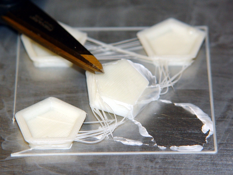
    Here’s what the film looks like under the start of a quartet of dodecahedrons I ran off to see if they stuck properly:

    ABS coating on aluminum build plate
    ABS coating on aluminum build plate

    The bottom surface looks like it was machined: dead flat,nice edges, good thread definition. The parts stick like they were glued to the surface, with no tendency to pull up at the corners.

    The Outline thread shows some adhesion trouble for the first 10 mm or so. After that, it’s nailed right to the ABS film. That’s why I use Outline, at least until I figure out a better way to start the thread.

    After I finish the next two plates, I’ll have a somewhat quick-change build platform: pull the hot plate off (holding it with pliers!) and slap a new one on. Not as convenient as the ABP, but much better for building precision parts like gears and extruder motor mounts.

  • Miniature Ball Bearing Sizes

    Having had to look up ball bearing sizes far too often, here’s the table…

    Bearing ID OD Thick
    603 3 9 5
    623 3 10 4
    633 3 13 5
    683 3 7 3
    693 3 8 4
    605 5 14 5
    625 5 16 5
    635 5 19 6
    606 6 17 6
    626 6 19 6
    608 8 22 7
    629 9 26 8

    The first digit is something like the bearing type; I think 6xx = miniature bearings.

    The second digit has something to do with the overall size, but is a code rather than an actual dimension.

    The last digit is, hal-lay-loo-ya, the actual bore diameter.

    [Update: Shows what I know; an excellent explanation of the numbers lives there. The short summary:

    • First digit: bearing type, 6 = single row deep groove
    • Second digit: series, 0 = extra light, 2 = light, 3 = medium duty, 8 & 9 = thinner
    • If three digits, third digit = ID in mm
    • If four digits, last two = ID/5, except 00-03 = 10/12/15/17

    Moral: always verify everything you read on the InterTubes!]

    Of course, a randomly chosen eBay listing will list the bearing size as:

    • ID x thickness x OD
    • OD x thickness x ID
    • ID x OD x thickness
    • and be wrong in at least one dimension

    Of most interest to Thing-O-Matic hackers: a 635 bearing ought to fit a NEMA 17 stepper shaft (pay attention if you’re buying surplus: not all are 5 mm) and slip into the same hole as a 626 bearing.

    Alas, there seems to be no 5 mm ID bearing equivalent to the 606 bearing in the MK5 extruder head, but a 0.5 mm = 20 mil shim around the outside would adapt a 625 to that hole. Might take some careful forming, though.

    Buy ’em in bulk and save…