The Smell of Molten Projects in the Morning

Ed Nisley's Blog: Shop notes, electronics, firmware, machinery, 3D printing, laser cuttery, and curiosities. Contents: 100% human thinking, 0% AI slop.

Tag: CNC

Making parts with mathematics

  • Thing-O-Matic: Revised Homing

    After adding F feed speed parameters to all the G0 commands in my start.gcode (to work around that bug), I decided to use the new-with-firmware-2.8 feature that stores the home offsets in the Thing-O-Matic’s EEPROM. That turned out to be, one might say, a thinly documented feature, so this may be a useful summary…

    The Official Way to set the EEPROM, which you can find in ReplicatorG/scripts/calibration/Thing-O-Matic calibration.gcode, goes a little something like this:

    • Manually position the nozzle dead center on the build plate, just touching the surface
    • Use G92 to set all axes to 0.0
    • Home the axes to the switches
    • Use M131 X Y Z A B to store the current values in EEPROM

    Having already found good values for those offsets as part of the aluminum build plate adventure, I jammed them into EEPROM using RepG’s Machine→Motherboard Onboard Preferences. The values I’m using are:

    • X = -53.0
    • Y = -59.0
    • Z = 116.0

    For some unknown reason that has nothing to do with floating point representation (I mean sheesh even the 32-bit version of IEEE 754 floating point has at least 10 decimal digits of precsion), RepG modifies only the negative values sufficiently to be bothersome:

    • X = -52.964
    • Y = -58.976

    Having stored the offsets, I wondered how to fetch them. That is also, of course, completely undocumented, but I eventually traced down the answer in (deep breath)

    skein_engines/skeinforge-35/skeinforge_application/prefs/SF35-Thingomatic-HBP-Stepstruder/alterations/start.gcode

    That’s not true for all the start.gcode files you might find, though, and there are many such in far more obvious places.

    So, OK, I fetch the EEPROM coordinates using M132 after doing both the coarse home (they’ll be pretty close) and the fine home (they’ll be dead on, modulo the changes), then wipe the nozzle and poke the Z-minimum height switch (which is why I really really care about random changes in the stored values) to find the actual height above the aluminum build surface.

    At exactly this position it would be nice to set only the Z height to the actual switch thickness, but G92 sets all un-mentioned axes to zero, so you can’t set just one axis. I have no idea how M131 and M132 behaves in that regard; none of this stuff is documented anywhere that I can find and this stopped being funny a while ago.

    So, knowing the XYZ coordinates of the switch, I reset the XYZAB axes using G92.

    The current working start.gcode that I devoutly hope will continue to work for a while:

    (---- start.gcode begins ----)
    (MakerBot Thing-O-Matic with aluminum HBP and Z-min platform switch)
    (Tweaked for TOM 286 - Ruttmeister MK5 stepper extruder mod)
    (Ed Nisley - KE4ZNU - July 2011)
    (Hack to work around bad G0 speed)
    (- set initial conditions)
    G21		(set units to mm)
    G90		(set positioning to absolute)
    (- begin heating)
    M104 S210 T0	(extruder head)
    M109 S110 T0	(HBP)
    (- coarse home axes)
    G162 Z F1000	(home Z to get nozzle out of danger zone)
    G161 Y F4000	(retract Y to get X out of front opening)
    G161 X F4000	(now safe to home X)
    M132 X Y Z A B	(fetch home offsets from EEPROM)
    (- fine home axes)
    G0 X-51 Y-55 Z114 F400	(back off switches)
    G161 Y F200
    G161 X F200
    G162 Z F200
    M132 X Y Z A B	(fetch home offsets from EEPROM)
    (- manual nozzle wipe)
    G0 F6000 X0 Y0 Z10	(pause at center to build confidence)
    G4 P500
    G0 X40 Y-57.0 Z10	(move to front, avoid wiper blade)
    G0 X56				(to wipe station)
    G0 Z6.0				(down to wipe level)
    M6 T0				(wait for temperature settling)
    G1 Y-45	F1000		(slowly wipe nozzle)
    (-----------------------------------------------)
    (- Make sure the XY position matches the G92    )
    (- home Z downward to platform switch)
    G0 F6000 X56.4 Y7.6 Z3		(get over build platform switch)
    G161 Z0 F50					(home downward very slowly)
    G92 X56.4 Y7.6 Z1.60		(set Z height)
    G0 F6000 Z6.0				(back off switch to wipe level)
    (-----------------------------------------------)
    (- start extruder and re-wipe)
    G0 X56 Y-45     (set up for wipe from rear)
    G1 Y-57.0 F1000 (wipe to front)
    M108 R2.0		(set stepper extruder speed)
    M101			(Extruder on, forward)
    G4 P4000  	    (take up slack, get pressure)
    M103			(Extruder off)
    G4 P4000  	    (Wait for filament to stop oozing)
    G1 Y-45	F1000	(slowly wipe nozzle again)
    G0 F6000 X0		(get away from wiper blade)
    (- build some pressure)
    M108 R2.0		(set stepper extruder speed)
    M101			(start extruder)
    G4 P100			(run for a bit)
    (---- start.gcode ends ----)


    For what it’s worth, I put that file in the sf_40_alterations directory, blew away the previous versions in all the profiles, and replaced them with symlinks to that single file. When the next change comes along, I can modify one file and all the profiles will pick up the change at once.

  • Helmet Mirror: Smaller Mirror Shaft

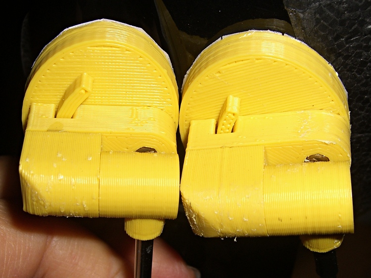
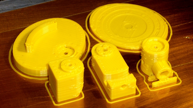
    This is the slightly smaller mount corresponding to the OpenSCAD code there for the two-section inspection mirror shaft, hot from the printer:

    Helmet mirror mount on build platform - smaller mirror shaft
    Helmet mirror mount on build platform – smaller mirror shaft

    It’s about the same as the previous version, despite trimming a few millimeters from the diameters and spacings:

    Helmet mirror mount size comparison
    Helmet mirror mount size comparison

    I’ll print the next one in a darker color. At least it’s not pink…

    The OpenSCAD source:

    // Helmet mirror mount
    // Ed Nisley KE4ZNU June 2011
    
    include </home/ed/Thing-O-Matic/lib/MCAD/units.scad>
    include </home/ed/Thing-O-Matic/lib/MCAD/boxes.scad>
    include </home/ed/Thing-O-Matic/lib/visibone_colors.scad>
    
    //-- Layout Control
    
    Layout = "Build";					// Build Fit Show None
    
    Examine = "None";				// AzMount ElMount ElBody ElPlate HelmetPlate None
    
    //-- Extrusion parameters
    
    ThreadThick = 0.33;
    ThreadWT = 2.0;
    ThreadWidth = ThreadThick * ThreadWT;
    
    HoleWindage = 0;			// enlarge hole dia by this amount
    
    //-- Useful sizes
    
    Tap2_56 = 0.070 * inch;
    Clear2_56 = 0.082 * inch;
    Head2_56 = 0.156 * inch;
    Head2_56Thick = 0.055 * inch;
    Nut2_56Dia = 0.204 * inch;
    Nut2_56Thick = 0.065 * inch;
    
    Tap3_48 = 0.079 * inch;
    Clear3_48 = 0.096 * inch;
    Head3_48 = 0.184 * inch;
    Head3_48Thick = 0.058 * inch;
    Nut3_48Dia = 0.201 * inch;
    Nut3_48Thick = 0.073 * inch;
    
    Tap4_40 = 0.089 * inch;
    Clear4_40 = 0.110 * inch;
    Head4_40 = 0.211 * inch;
    Head4_40Thick = 0.065 * inch;
    Nut4_40Dia = 0.228 * inch;
    Nut4_40Thick = 0.086 * inch;
    
    //-- Azimuth Mount
    
    AzMountDia = 12.0;
    AzMountLength = 14.0;
    
    AzFacets = 30;
    
    echo(str("Azmuth mount dia: ",AzMountDia," length: ",AzMountLength));
    
    //-- Mirror sizes
    
    MirrorShaftDia = 3.60;
    MirrorShaftOffset = -1.5;				// vertical offset from center of AzMountBody
    MirrorShoulderLen = 3*MirrorShaftDia;
    MirrorShoulderDia = min(AzMountDia,MirrorShaftDia + 6*ThreadWidth);
    
    MirrorStudDia = Tap3_48;
    MirrorStudLen = 2.0;
    
    //-- Elevation Mount / Body / Plate
    
    ElMountDia = AzMountDia;
    ElMountLength = 2.0 + ElMountDia;
    
    ElMountBase = 2.0;
    
    ElMountRounding = 2.0;
    
    ElMountFacets = AzFacets;
    
    ElBodyWidth = ElMountDia;
    ElBodyBlockLength = ElMountLength + AzMountLength/2 - MirrorShaftOffset;
    ElBodyThick = 8.0;
    
    echo(str("Elevation body overall: ",(ElBodyBlockLength + ElBodyWidth/2)," width: ",ElBodyWidth));
    
    ElPlateTall = ElBodyBlockLength + 0.70*ElBodyWidth;
    ElPlateWidth = 1.25 * ElPlateTall;
    ElPlateThick = Nut3_48Thick + 3*ThreadThick;
    
    ElPlatePlusX = ElPlateThick + (ElMountDia/2 + ElMountBase) + ElBodyThick;
    
    echo(str("Elevation plate tall: ",ElPlateTall," width: ",ElPlateWidth));
    
    ElArcRadius = (3/4) * ElBodyBlockLength;
    ElArcThick = 4*ThreadWidth;
    ElArcHeight = (1/2) * ElBodyThick;
    ElArcAngle = 35;
    ElArcFacets = 32;
    
    ElPlateFacets = 52;
    
    //-- Helmet Interface Plate
    
    HelmetCX = 60.0;
    HelmetMX = 4.0;
    HelmetRX = (pow(HelmetMX,2) + pow(HelmetCX,2)/4)/(2*HelmetMX);
    
    HelmetPlateC = max(ElPlateTall,ElPlateWidth);
    HelmetPlateTheta = atan(HelmetPlateC/HelmetRX);
    HelmetPlateM = 2*HelmetRX*pow(sin(HelmetPlateTheta/4),2);
    
    HelmetPlateThick = ThreadThick*(ceil(HelmetPlateM/ThreadThick) + 1);
    
    //-- Bearing Interfaces
    
    BearingWidth = 3*ThreadWidth;
    
    BearingOverlap = 3*ThreadThick;
    BearingClearance = 1*ThreadThick;
    
    BearingStudDia = min(AzMountDia,ElBodyWidth) - 2*BearingWidth;
    
    //-- Convenience values
    
    Protrusion = 0.1;		// make holes look good
    
    //----------------------
    // Useful routines
    
    module PolyCyl(Dia,Height) {			// based on nophead's polyholes
    
      Sides = ceil(Dia) + 2;
      FixDia = Dia / cos(180/Sides);
    
      cylinder(r=(FixDia + HoleWindage)/2,
               h=Height,
    	   $fn=Sides);
    }
    
    PegSize = 1.0;
    
    module ShowPegGrid(Size) {
    	for (x=[-5:5])
    	  for (y=[-5:5])
    		translate([x*10,y*10,Size/2])
    		  cube(Size,center=true);
    
    }
    
    //----------------------
    // Azimuth Mount
    
    module AzMount() {
    
      difference() {
    	union() {
    	  cylinder(r=AzMountDia/2,h=AzMountLength,$fn=AzFacets);		// body
    	  translate([0,0,AzMountLength/2 + MirrorShaftOffset])
    		rotate([-90,0,0])
    		  cylinder(r=MirrorShoulderDia/2,
    				   h=MirrorShoulderLen,$fn=AzFacets);				// mirror shaft shoulder
    
    	  if (Layout != "Fit")
    		for (y=[0:1])												// shoulder support
    		  translate([-AzMountDia/2,(4*y + AzMountDia/2 + ThreadWidth),0])
    			difference() {
    			  cube([AzMountDia,2*ThreadWidth,AzMountLength/6]);
    			  translate([AzMountDia/2,-Protrusion,AzMountLength/2 + MirrorShaftOffset])
    				rotate([-90,0,0])
    				  cylinder(r=MirrorShoulderDia/2,h=ThreadWidth + 2*Protrusion);
    			}
    	}
    
        translate([0,-Head3_48/2,AzMountLength/2 + MirrorShaftOffset])
          rotate([-90,0,0])
    		PolyCyl(MirrorShaftDia,(AzMountDia + MirrorShoulderLen));	// mirror shaft
    
        translate([0,-(Head3_48/2 - Protrusion),AzMountLength/2 + MirrorShaftOffset])
    	  rotate([90,0,0])
    		PolyCyl(MirrorStudDia,MirrorStudLen+Protrusion);			// mirror stud
    
        translate([0,0,
    	       Head3_48Thick - (AzMountLength - MirrorShaftDia)/2 + MirrorShaftOffset - Protrusion])
          PolyCyl(Head3_48,AzMountLength + Protrusion);					// mounting screw head
    
        translate([0,0,-Protrusion])
          cylinder(r=(Clear3_48 + HoleWindage)/2,
    	  h=(AzMountLength + 2*Protrusion),
    	  $fn=ceil(Clear3_48)+2);										// mounting screw clearance
    
    	translate([0,0,AzMountLength/2 + Head3_48Thick + MirrorShaftDia/2 + MirrorShaftOffset - Protrusion])
    	  cylinder(r1=(Head3_48/cos(180/7) + HoleWindage)/2,
    			   r2=Clear3_48/2,
    			   h=(3*ThreadThick + Protrusion),
    			   $fn=7);												// overhang support
    
        translate([0,0,AzMountLength/2 + MirrorShaftOffset])
          rotate([0,90,0])
    		PolyCyl(Tap2_56,AzMountDia/2 + Protrusion);					// setscrew hole
    
        translate([0,0,AzMountLength - (BearingOverlap + BearingClearance)])
    	  PolyCyl(BearingStudDia,
    			  BearingOverlap + BearingClearance + Protrusion);		// bearing surface
    
      }
    
    }
    
    //----------------------
    // Elevation Mount
    
    module ElMount() {
    
      difference() {
    
    	union() {
    
    	  translate([(ElMountDia/4 + ElMountBase/2),0,(ElMountLength/2 + BearingOverlap)])
    		rotate([0,90,0])
    		  cube([ElMountLength,ElMountDia,(ElMountDia/2 + ElMountBase)],
    			  center=true);											// mounting block
    
    	  translate([0,0,BearingOverlap]) {
    //		color([0.4,0.3,0.3,0.7])
    		cylinder(r=ElMountDia/2,
    				 h=ElMountLength - ElMountDia/2,
    				 $fn=ElMountFacets);								// cylinder to Az
    
    //		color([0.3,0.4,0.3,0.7])
    		translate([0,0,ElMountLength - ElMountDia/2]) {				// curved interface
    		  intersection() {
    			cylinder(r=ElMountDia/2,h=ElMountDia/2,$fn=ElMountFacets);
    			translate([0,ElMountDia/2,0])
    			  rotate([90,0,0])
    				cylinder(r=ElMountDia/2,h=ElMountDia,$fn=ElMountFacets);
    		  }
    		}
    
    	  }
    
    	  cylinder(r=(BearingStudDia - HoleWindage)/2,h=BearingOverlap);	// bearing stud
    	}
    
    	translate([0,0,-Protrusion])
    	  PolyCyl(Tap3_48,(3/4)*ElMountLength + BearingOverlap + Protrusion);	// AzMount screw
      }
    }
    
    //----------------------
    // Elevation Body
    
    module ElBody() {
    
      difference() {
    	union() {
    	  translate([-ElBodyBlockLength,-ElBodyWidth/2,0])
    		cube([ElBodyBlockLength,ElBodyWidth,ElBodyThick]);
    	  translate([0,0,ElBodyThick])
    		cylinder(r=(ElBodyWidth - 2*BearingWidth)/2,h=BearingOverlap);
    	  cylinder(r=ElBodyWidth/2,h=ElBodyThick,$fn=ElMountFacets);
    	}
    
    	PolyCyl(Clear3_48,ElBodyThick + BearingOverlap + Protrusion);
    
    	translate([0,0,-Protrusion])
    	  PolyCyl(Head3_48,Head3_48Thick);
    
    	translate([-ElArcRadius,0,ElBodyThick - ElArcHeight/2])
    	  rotate([0,-90,0])
    		PolyCyl(Tap2_56,ElBodyBlockLength - ElArcRadius + Protrusion);
    
    	translate([0,0,ElBodyThick - (ElArcHeight + BearingClearance)])
    	  difference() {
    		cylinder(r=ElArcRadius + (ElArcThick/2 + BearingClearance),
    				 h=ElArcHeight + BearingClearance + Protrusion,
    				 $fn=ElArcFacets);
    		cylinder(r=ElArcRadius - (ElArcThick/2 + BearingClearance),
    				 h=ElArcHeight + BearingClearance + Protrusion,
    				 $fn=ElArcFacets);
    	  }
    
      }
    
    }
    
    //----------------------
    // Elevation Plate
    
    module ElPlate() {
    
      union() {
    	difference() {
    	  translate([ElBodyWidth/2 - ElPlateTall/2,0,0])
    		scale([ElPlateTall,ElPlateWidth,1.0])
    		  cylinder(r=0.5,h=ElPlateThick,$fn=ElPlateFacets);
    	  translate([0,0,-Protrusion])
    		PolyCyl(Tap3_48,ElPlateThick + 2*Protrusion);
    	  translate([0,0,ElPlateThick - (BearingOverlap + BearingClearance)])
    		PolyCyl(BearingStudDia,(BearingOverlap + BearingClearance) + Protrusion);
    	  translate([0,0,-Protrusion])
    		cylinder(r=Nut3_48Dia/2,h=(1.1*Nut3_48Thick + Protrusion),$fn=6);
    	}
    
    	translate([0,0,ElPlateThick])
    	difference() {
    	  cylinder(r=ElArcRadius + ElArcThick/2,
    			   h=ElArcHeight,
    			   $fn=ElArcFacets);
    	  cylinder(r=ElArcRadius - ElArcThick/2,
    			   h=ElArcHeight + Protrusion,
    			   $fn=ElArcFacets);
    	  rotate([0,0,90 - ElArcAngle])
    	    translate([ElArcRadius + ElArcThick,0,ElArcHeight/2])
    		  cube([2*ElArcRadius + ElArcThick,
    				2*ElArcRadius + ElArcThick,
    				ElArcHeight + Protrusion],
    				center=true);
    	  rotate([0,0,-(90 - ElArcAngle)])
    	    translate([ElArcRadius + ElArcThick,0,ElArcHeight/2])
    		  cube([2*ElArcRadius + ElArcThick,
    				2*ElArcRadius + ElArcThick,
    				ElArcHeight + Protrusion],
    				center=true);
    	}
      }
    }
    
    //----------------------
    // Helmet Interface Plate
    
    module HelmetPlate() {
    
      difference() {
    	scale([ElPlateTall,ElPlateWidth,1.0])
    	  cylinder(r=0.5,h=HelmetPlateThick,$fn=ElPlateFacets);
    
    	translate([0,0,HelmetRX + HelmetPlateThick - HelmetPlateM])
    	  sphere(r=HelmetRX,$fn=256,$fs=0.1);
    
      }
    }
    
    //----------------------
    // Lash it together
    
    if (Examine == "AzMount")
      AzMount();
    
    if (Examine == "ElMount")
      ElMount();
    
    if (Examine == "ElBody")
      ElBody();
    
    if (Examine == "ElPlate")
      ElPlate();
    
    if (Examine == "HelmetPlate")
      HelmetPlate();
    
    if ((Layout == "Build" || Layout == "Show") && Examine == "None") {
      translate([-10,-20,0])
    	rotate([0,0,90])					// mis-align top fill from ElMount
    	  AzMount();
    
      translate([-10,20,ElMountLength + BearingOverlap])
    	rotate([0,180,-90])
    	  ElMount();
    
      translate([0,0,0])
    	rotate([0,0,0])
    	  ElBody();
    
      translate([10,15,0])
    	rotate([0,0,215])					// mis-align top fill from ElBody
    	  ElPlate();
    
      translate([20,-20,0])
    	rotate([0,0,-45])
    	  HelmetPlate();
    
      if (Layout == "Show")
    	ShowPegGrid(PegSize);
    
    }
    
    if ((Layout == "Fit") && Examine == "None") {
      translate([0,0,-(AzMountLength/2 + MirrorShaftOffset)])
    	color(MFG) AzMount();
    
      translate([0,0,AzMountLength/2 - MirrorShaftOffset - BearingOverlap])
    	color(DHC) ElMount();
    //	color([  0/255, 204/255, 204/255,0.5]) ElMount();
    
    	translate([ElMountDia/2 + ElMountBase,0,0])
    	  rotate([0,90,0])
    		color(DFC) ElBody();
    
    	translate([ElPlatePlusX,0,0])
    	  rotate([180,90,0])
    		color(LHC) ElPlate();
    
    	translate([ElPlatePlusX,0,ElPlateTall/2 - ElBodyWidth/2])
    	  rotate([0,90,0])
    		color(LWM) HelmetPlate();
    }
    
  • Stepper Motor Back EMF

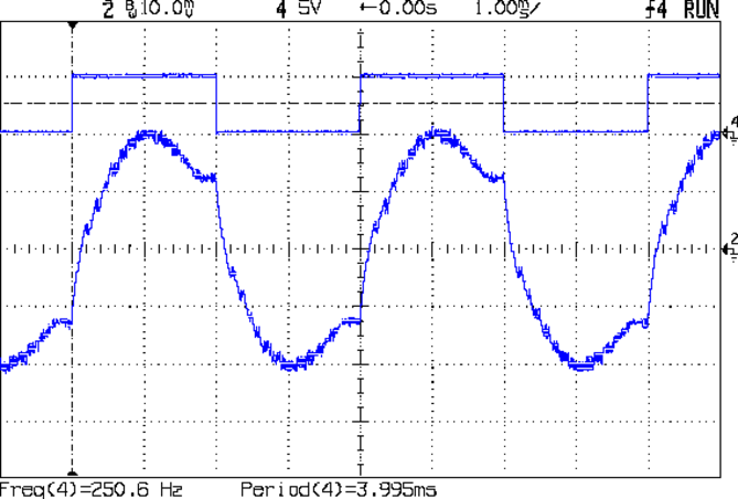
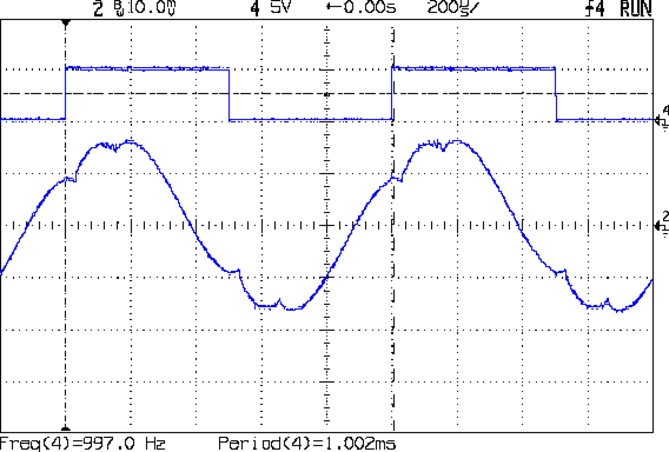
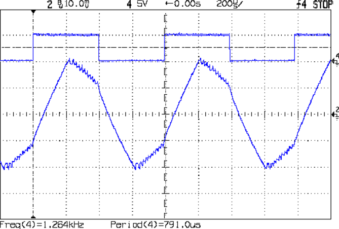
    Some simple measurements using that Pololu driver in its default mixed decay mode and that Arduino sync generator. The captions give the operating conditions; basically, I’m varying the rotation speed by cranking the signal generator driving the Pololu board.

    At 1 rev/s, it’s about as good as it gets:

    Back EMF - 9V 400mA 1 RPS
    Back EMF – 9V 400mA 1 RPS

    At 5 rev/s, the driver has trouble getting current out of the winding:

    Back EMF - 9V 400mA 5 RPS
    Back EMF – 9V 400mA 5 RPS

    At 10 rev/s, things are getting ugly:

    Back EMF - 9V 400mA 10 RPS
    Back EMF – 9V 400mA 10 RPS

    At 20 rev/s, the back EMF has pretty much taken control of the current and the driver is going along for the ride:

    Back EMF - 9V 400mA 20 RPS
    Back EMF – 9V 400mA 20 RPS

    At 25 rev/s, the driver produces only occasional dents in the waveform:

    Back EMF - 9V 400mA 25 RPS
    Back EMF – 9V 400mA 25 RPS

    At 25.3 rev/s, the motor stalled. Even with no back EMF (what with the rotor being stopped and buzzing in frustration), the driver can’t force the current to behave:

    Back EMF - 9V 400mA 25.3 RPS
    Back EMF – 9V 400mA 25.3 RPS

    I don’t have any way to measure the motor’s output torque, but at 1500 RPM there won’t be any worth mentioning.

    For what it’s worth, 25 rev/s means the driver is handling 40 k steps/sec = 25 µs/step. The motors in a Thing-O-Matic run at 3 rev/s to move the XY stages at 100 mm/s, so scale what you see here accordingly.

  • Helmet Mirror Mount: First Light

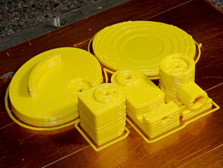
    Printing went smoothly after two preliminary passes to work out the sizes and alignments; this is the second pass, which you can tell because the mirror shoulder has three supports instead of the two shown in the solid model:

    Mirror mount parts on build plate
    Mirror mount parts on build plate

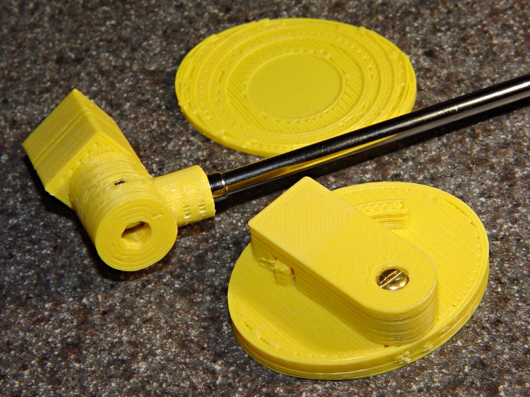
    One view of the parts, with the mirror shaft in place:

    Mirror mount partial assembly - top
    Mirror mount partial assembly – top

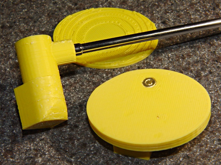
    Another view, showing the bottom of the Elevation Plate with the recessed nut:

    Mirror mount parts partial assembly - bottom
    Mirror mount parts partial assembly – bottom

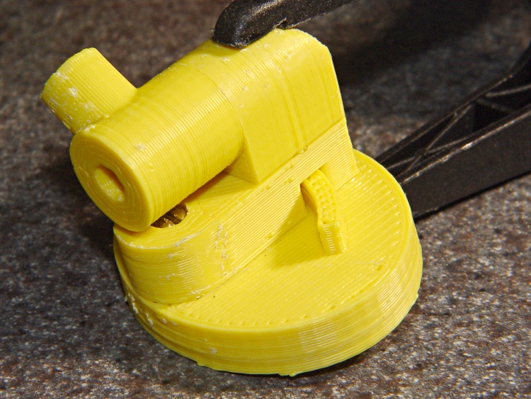
    Assembling the two glue joints required an overnight clamping:

    Mirror mount - glued and clamped
    Mirror mount – glued and clamped

    Then a layer of double-stick foam tape affixes it firmly to the helmet:

    Mirror mount - on helmet
    Mirror mount – on helmet

    It’s a bit too big and way ugly, but works pretty much as expected.

    Two lengths of heatshrink tubing now lock the mirror shaft sections in place; they tended to rotate slightly under normal vibration.

    The OpenSCAD code and model have a few modifications from this object. The next one won’t have the third section of mirror shaft, which makes the shoulder and Az Mount smaller, and the Az Mount is 1 mm closer to the El Body. That shaves a few millimeters off the whole thing.

    The mirror clamp out there on the end is much too large and has too many fiddly parts. I think a little printed doodad would work, but that’s in the nature of fine tuning.

  • Helmet Mirror Mount: Solid Model

    Helmet mirror mount - 3D model - Fit layout
    Helmet mirror mount – 3D model – Fit layout

    After a bit of OpenSCAD twiddling, those doodles turned into a printable model. This view shows what it looks like all neatly assembled:

    The tiny hole on the top of the Elevation Body accepts a 2-56 setscrew that grabs the arc protruding from the Elevation Plate and locks the up-and-down setting. The Azimuth Mount pivots on the 3-48 screw holding it to the Elevation Mount.

    Both of those pivots must be loose enough to move when you bump the mirror and tight enough to stay put in normal use. It’s a delicate balance and I’m not convinced this will work for the long term, but it’s a brassboard.

    The 2-56 stud on the end of the mirror shaft screws into a socket in the rear side of the Az Mount. Another 2-56 setscrew in the Az Mount (facing the El Body), grabs the side of the shaft and prevents it from rotating.

    All the parts lay out on their backs for printing, with a grid to show how they fit on the build platform:

    Helmet mirror mount - 3D model - Show layout
    Helmet mirror mount – 3D model – Show layout

    The mirror shaft shoulder on the Az Mount (front center) sticks out in mid air and requires a little bit of support.

    The El Mount (left rear) builds surprisingly well with its curved top surface downward. If it’s rotated 90 degrees with the curve facing to the left, Skeinforge grumps about not being able to do something or another and generates totally bogus G-Code.

    The Helmet Plate has a 3 mm deep depression that more-or-less corresponds to the helmet’s surface. It’s gouged out by a huge sphere sitting on the plate, with a radius calculated from the measured helmet curvature.

    The OpenSCAD source code has two useful parameters near the top:

    • Layout selects the overall appearance: Fit, Show, or Build
    • Examine selects a single part for inspection & tweakage

    You’ll need the MCAD and Visibone libraries to make this work. It’s the original code, without the tweaks to the grid mentioned in the comments there:

    // Helmet mirror mount
    // Ed Nisley KE4ZNU June 2011
    
    include </home/ed/Thing-O-Matic/lib/MCAD/units.scad>
    include </home/ed/Thing-O-Matic/lib/MCAD/boxes.scad>
    include </home/ed/Thing-O-Matic/lib/visibone_colors.scad>
    
    //-- Layout Control
    
    Layout = "Show";					// Build Fit Show None
    
    Examine = "None";				// AzMount ElMount ElBody ElPlate HelmetPlate None
    
    //-- Extrusion parameters
    
    ThreadThick = 0.33;
    ThreadWT = 2.0;
    ThreadWidth = ThreadThick * ThreadWT;
    
    HoleWindage = 0;			// enlarge hole dia by this amount
    
    //-- Useful sizes
    
    Tap2_56 = 0.070 * inch;
    Clear2_56 = 0.082 * inch;
    Head2_56 = 0.156 * inch;
    Head2_56Thick = 0.055 * inch;
    Nut2_56Dia = 0.204 * inch;
    Nut2_56Thick = 0.065 * inch;
    
    Tap3_48 = 0.079 * inch;
    Clear3_48 = 0.096 * inch;
    Head3_48 = 0.184 * inch;
    Head3_48Thick = 0.058 * inch;
    Nut3_48Dia = 0.201 * inch;
    Nut3_48Thick = 0.073 * inch;
    
    Tap4_40 = 0.089 * inch;
    Clear4_40 = 0.110 * inch;
    Head4_40 = 0.211 * inch;
    Head4_40Thick = 0.065 * inch;
    Nut4_40Dia = 0.228 * inch;
    Nut4_40Thick = 0.086 * inch;
    
    //-- Azimuth Mount
    
    AzMountDia = 12.0;
    AzMountLength = 14.0;
    
    AzFacets = 30;
    
    echo(str("Azmuth mount dia: ",AzMountDia," length: ",AzMountLength));
    
    //-- Mirror sizes
    
    MirrorShaftDia = 3.60;
    MirrorShaftOffset = -1.5;				// vertical offset from center of AzMountBody
    MirrorShoulderLen = 3*MirrorShaftDia;
    MirrorShoulderDia = min(AzMountDia,MirrorShaftDia + 6*ThreadWidth);
    
    MirrorStudDia = Tap3_48;
    MirrorStudLen = 2.0;
    
    //-- Elevation Mount / Body / Plate
    
    ElMountDia = AzMountDia;
    ElMountLength = 2.0 + ElMountDia;
    
    ElMountBase = 2.0;
    
    ElMountRounding = 2.0;
    
    ElMountFacets = AzFacets;
    
    ElBodyWidth = ElMountDia;
    ElBodyBlockLength = ElMountLength + AzMountLength/2 - MirrorShaftOffset;
    ElBodyThick = 8.0;
    
    echo(str("Elevation body overall: ",(ElBodyBlockLength + ElBodyWidth/2)," width: ",ElBodyWidth));
    
    ElPlateTall = ElBodyBlockLength + 0.70*ElBodyWidth;
    ElPlateWidth = 1.25 * ElPlateTall;
    ElPlateThick = ceil(4.0 / ThreadThick) * ThreadThick;
    
    ElPlatePlusX = ElPlateThick + (ElMountDia/2 + ElMountBase) + ElBodyThick;
    
    echo(str("Elevation plate tall: ",ElPlateTall," width: ",ElPlateWidth));
    
    ElArcRadius = (3/4) * ElBodyBlockLength;
    ElArcThick = 4*ThreadWidth;
    ElArcHeight = (1/2) * ElBodyThick;
    ElArcAngle = 35;
    ElArcFacets = 32;
    
    ElPlateFacets = 52;
    
    //-- Helmet Interface Plate
    
    HelmetCX = 60.0;
    HelmetMX = 4.0;
    HelmetRX = (pow(HelmetMX,2) + pow(HelmetCX,2)/4)/(2*HelmetMX);
    
    HelmetPlateC = max(ElPlateTall,ElPlateWidth);
    HelmetPlateTheta = atan(HelmetPlateC/HelmetRX);
    HelmetPlateM = 2*HelmetRX*pow(sin(HelmetPlateTheta/4),2);
    
    HelmetPlateThick = ThreadThick*(ceil(HelmetPlateM/ThreadThick) + 1);
    
    //-- Bearing Interfaces
    
    BearingWidth = 3*ThreadWidth;
    
    BearingOverlap = 3*ThreadThick;
    BearingClearance = 1*ThreadThick;
    
    BearingStudDia = min(AzMountDia,ElBodyWidth) - 2*BearingWidth;
    
    //-- Convenience values
    
    Protrusion = 0.1;		// make holes look good
    
    PegSize = 1.0;
    
    //----------------------
    // Useful routines
    
    module PolyCyl(Dia,Height) {			// based on nophead's polyholes
    
      Sides = ceil(Dia) + 2;
      FixDia = Dia / cos(180/Sides);
    
      cylinder(r=(FixDia + HoleWindage)/2,
               h=Height,
    	   $fn=Sides);
    }
    
    module ShowPegGrid(Size) {
    	for (x=[-5:5])
    	  for (y=[-5:5])
    		translate([x*10,y*10,Size/2])
    		  cube(Size,center=true);
    
    }
    
    //----------------------
    // Azimuth Mount
    
    module AzMount() {
    
      difference() {
    	union() {
    	  cylinder(r=AzMountDia/2,h=AzMountLength,$fn=AzFacets);		// body
    	  translate([0,0,AzMountLength/2 + MirrorShaftOffset])
    		rotate([-90,0,0])
    		  cylinder(r=MirrorShoulderDia/2,
    				   h=MirrorShoulderLen,$fn=AzFacets);				// mirror shaft shoulder
    
    	  if (Layout != "Fit")
    		for (y=[0:1])												// shoulder support
    		  translate([-AzMountDia/2,(4*y + AzMountDia/2 + ThreadWidth),0])
    			difference() {
    			  cube([AzMountDia,2*ThreadWidth,AzMountLength/6]);
    			  translate([AzMountDia/2,-Protrusion,AzMountLength/2 + MirrorShaftOffset])
    				rotate([-90,0,0])
    				  cylinder(r=MirrorShoulderDia/2,h=ThreadWidth + 2*Protrusion);
    			}
    	}
    
        translate([0,-Head3_48/2,AzMountLength/2 + MirrorShaftOffset])
          rotate([-90,0,0])
    		PolyCyl(MirrorShaftDia,(AzMountDia + MirrorShoulderLen));	// mirror shaft
    
        translate([0,-(Head3_48/2 - Protrusion),AzMountLength/2 + MirrorShaftOffset])
    	  rotate([90,0,0])
    		PolyCyl(MirrorStudDia,MirrorStudLen+Protrusion);			// mirror stud
    
        translate([0,0,
    	       Head3_48Thick - (AzMountLength - MirrorShaftDia)/2 + MirrorShaftOffset - Protrusion])
          PolyCyl(Head3_48,AzMountLength + Protrusion);					// mounting screw head
    
        translate([0,0,-Protrusion])
          cylinder(r=(Clear3_48 + HoleWindage)/2,
    	  h=(AzMountLength + 2*Protrusion),
    	  $fn=ceil(Clear3_48)+2);										// mounting screw clearance
    
    	translate([0,0,AzMountLength/2 + Head3_48Thick + MirrorShaftDia/2 + MirrorShaftOffset - Protrusion])
    	  cylinder(r1=(Head3_48/cos(180/7) + HoleWindage)/2,
    			   r2=Clear3_48/2,
    			   h=(3*ThreadThick + Protrusion),
    			   $fn=7);												// overhang support
    
        translate([0,0,AzMountLength/2 + MirrorShaftOffset])
          rotate([0,90,0])
    		PolyCyl(Tap2_56,AzMountDia/2 + Protrusion);					// setscrew hole
    
        translate([0,0,AzMountLength - (BearingOverlap + BearingClearance)])
    	  PolyCyl(BearingStudDia,
    			  BearingOverlap + BearingClearance + Protrusion);		// bearing surface
    
      }
    
    }
    
    //----------------------
    // Elevation Mount
    
    module ElMount() {
    
      difference() {
    
    	union() {
    
    	  translate([(ElMountDia/4 + ElMountBase/2),0,(ElMountLength/2 + BearingOverlap)])
    		rotate([0,90,0])
    		  cube([ElMountLength,ElMountDia,(ElMountDia/2 + ElMountBase)],
    			  center=true);											// mounting block
    
    	  translate([0,0,BearingOverlap]) {
    //		color([0.4,0.3,0.3,0.7])
    		cylinder(r=ElMountDia/2,
    				 h=ElMountLength - ElMountDia/2,
    				 $fn=ElMountFacets);								// cylinder to Az
    
    //		color([0.3,0.4,0.3,0.7])
    		translate([0,0,ElMountLength - ElMountDia/2]) {				// curved interface
    		  intersection() {
    			cylinder(r=ElMountDia/2,h=ElMountDia/2,$fn=ElMountFacets);
    			translate([0,ElMountDia/2,0])
    			  rotate([90,0,0])
    				cylinder(r=ElMountDia/2,h=ElMountDia,$fn=ElMountFacets);
    		  }
    		}
    
    	  }
    
    	  cylinder(r=(BearingStudDia - HoleWindage)/2,h=BearingOverlap);	// bearing stud
    	}
    
    	translate([0,0,-Protrusion])
    	  PolyCyl(Tap3_48,(3/4)*ElMountLength + BearingOverlap + Protrusion);	// AzMount screw
      }
    }
    
    //----------------------
    // Elevation Body
    
    module ElBody() {
    
      difference() {
    	union() {
    	  translate([-ElBodyBlockLength,-ElBodyWidth/2,0])
    		cube([ElBodyBlockLength,ElBodyWidth,ElBodyThick]);
    	  translate([0,0,ElBodyThick])
    		cylinder(r=(ElBodyWidth - 2*BearingWidth)/2,h=BearingOverlap);
    	  cylinder(r=ElBodyWidth/2,h=ElBodyThick,$fn=ElMountFacets);
    	}
    
    	PolyCyl(Clear3_48,ElBodyThick + BearingOverlap + Protrusion);
    
    	translate([0,0,-Protrusion])
    	  PolyCyl(Head3_48,Head3_48Thick);
    
    	translate([-ElArcRadius,0,ElBodyThick - ElArcHeight/2])
    	  rotate([0,-90,0])
    		PolyCyl(Tap2_56,ElBodyBlockLength - ElArcRadius + Protrusion);
    
    	translate([0,0,ElBodyThick - (ElArcHeight + BearingClearance)])
    	  difference() {
    		cylinder(r=ElArcRadius + (ElArcThick/2 + BearingClearance),
    				 h=ElArcHeight + BearingClearance + Protrusion,
    				 $fn=ElArcFacets);
    		cylinder(r=ElArcRadius - (ElArcThick/2 + BearingClearance),
    				 h=ElArcHeight + BearingClearance + Protrusion,
    				 $fn=ElArcFacets);
    	  }
    
      }
    
    }
    
    //----------------------
    // Elevation Plate
    
    module ElPlate() {
    
      union() {
    	difference() {
    	  translate([ElBodyWidth/2 - ElPlateTall/2,0,0])
    		scale([ElPlateTall,ElPlateWidth,1.0])
    		  cylinder(r=0.5,h=ElPlateThick,$fn=ElPlateFacets);
    	  translate([0,0,-Protrusion])
    		PolyCyl(Tap3_48,ElPlateThick + 2*Protrusion);
    	  translate([0,0,ElPlateThick - (BearingOverlap + BearingClearance)])
    		PolyCyl(BearingStudDia,(BearingOverlap + BearingClearance) + Protrusion);
    	  translate([0,0,-Protrusion])
    		cylinder(r=Nut3_48Dia/2,h=(1.1*Nut3_48Thick + Protrusion),$fn=6);
    	}
    
    	translate([0,0,ElPlateThick])
    	difference() {
    	  cylinder(r=ElArcRadius + ElArcThick/2,
    			   h=ElArcHeight,
    			   $fn=ElArcFacets);
    	  cylinder(r=ElArcRadius - ElArcThick/2,
    			   h=ElArcHeight + Protrusion,
    			   $fn=ElArcFacets);
    	  rotate([0,0,90 - ElArcAngle])
    	    translate([ElArcRadius + ElArcThick,0,ElArcHeight/2])
    		  cube([2*ElArcRadius + ElArcThick,
    				2*ElArcRadius + ElArcThick,
    				ElArcHeight + Protrusion],
    				center=true);
    	  rotate([0,0,-(90 - ElArcAngle)])
    	    translate([ElArcRadius + ElArcThick,0,ElArcHeight/2])
    		  cube([2*ElArcRadius + ElArcThick,
    				2*ElArcRadius + ElArcThick,
    				ElArcHeight + Protrusion],
    				center=true);
    	}
      }
    }
    
    //----------------------
    // Helmet Interface Plate
    
    module HelmetPlate() {
    
      difference() {
    	scale([ElPlateTall,ElPlateWidth,1.0])
    	  cylinder(r=0.5,h=HelmetPlateThick,$fn=ElPlateFacets);
    
    	translate([0,0,HelmetRX + HelmetPlateThick - HelmetPlateM])
    	  sphere(r=HelmetRX,$fn=256,$fs=0.1);
    
      }
    }
    
    //----------------------
    // Lash it together
    
    if (Examine == "AzMount")
      AzMount();
    
    if (Examine == "ElMount")
      ElMount();
    
    if (Examine == "ElBody")
      ElBody();
    
    if (Examine == "ElPlate")
      ElPlate();
    
    if (Examine == "HelmetPlate")
      HelmetPlate();
    
    if ((Layout == "Build" || Layout == "Show") && Examine == "None") {
      translate([-10,-20,0])
    	rotate([0,0,90])					// mis-align top fill from ElMount
    	  AzMount();
    
      translate([-10,20,ElMountLength + BearingOverlap])
    	rotate([0,180,-90])
    	  ElMount();
    
      translate([0,0,0])
    	rotate([0,0,0])
    	  ElBody();
    
      translate([10,15,0])
    	rotate([0,0,215])					// mis-align top fill from ElBody
    	  ElPlate();
    
      translate([20,-20,0])
    	rotate([0,0,-45])
    	  HelmetPlate();
    
      if (Layout == "Show")
    	ShowPegGrid(PegSize);
    
    }
    
    if ((Layout == "Fit") && Examine == "None") {
      translate([0,0,-(AzMountLength/2 + MirrorShaftOffset)])
    	color(MFG) AzMount();
    
      translate([0,0,AzMountLength/2 - MirrorShaftOffset - BearingOverlap])
    	color(DHC) ElMount();
    //	color([  0/255, 204/255, 204/255,0.5]) ElMount();
    
    	translate([ElMountDia/2 + ElMountBase,0,0])
    	  rotate([0,90,0])
    		color(DFC) ElBody();
    
    	translate([ElPlatePlusX,0,0])
    	  rotate([180,90,0])
    		color(LHC) ElPlate();
    
    	translate([ElPlatePlusX,0,ElPlateTall/2 - ElBodyWidth/2])
    	  rotate([0,90,0])
    		color(LWM) HelmetPlate();
    }
    
  • OpenSCAD Layout Grid

    OpenSCAD Build Surface Grid
    OpenSCAD Build Surface Grid

    This OpenSCAD module spreads an array of cubes across the otherwise featureless preview window, so I know whether the gizmo I’m building or the parts I’m arranging actually fit on the Thing-O-Matic’s build platform. This doesn’t get out to the very edge, but if it looks close, then I should pay more attention anyway.

    module ShowPegGrid(Size) {
    
     for (x=[-5:5])
      for (y=[-5:5])
       translate([x*10,y*10,Size/2])
        cube(Size,center=true);
    
    }
    
    ShowPegGrid(1.0);
    

    You obviously don’t want to extrude these things, so put the ShowPegGrid() statement inside an if, so you can turn it off for the final build layout.

  • Stepper Motor Winding Current Rise Time

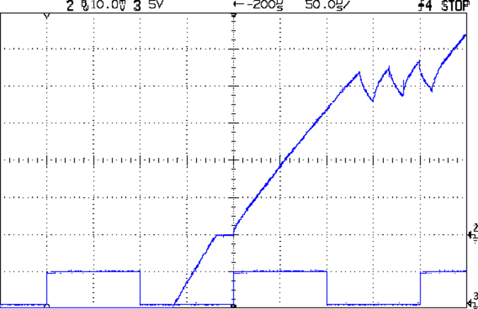
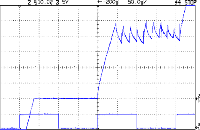
    Here’s how the stepper drive voltage affects the current rise, using that kludge to sync the scope on one of those motors with L=2.6 mH and R=2.2 Ω. The peak winding current is 1 A, so the first step current-limits at 200 mA.

    At 9 V:

    Current Rise - 9 V 1A 3 RPS
    Current Rise – 9 V 1A 3 RPS

    At 18 V:

    Current Rise - 18 V 1A 3 RPS
    Current Rise – 18 V 1A 3 RPS

    Knowing the rise time and current change, you can calculate the actual voltage across the inductor using:

    VL = L di/dt

    With 9 V drive the motor sees:

    4.4 V = 2.6 mH x 220 mA / 130 us

    With 18 V drive the motor sees:

    14 V = 2.6 mH x 240 mA / 45 us

    So, in round numbers, the driver MOSFETs, winding resistance, and all the crappy solderless breadboard connections soak up about 4 V of the available supply voltage. There’s some back EMF in there, too, but I haven’t measured that part of the puzzle yet.

    The motor is turning at 3 rev/s in 1/8 microstepping mode, so each microstep is:
    200 us = 1/(3 rev/s x 1600 step/rev)