Ed Nisley's Blog: Shop notes, electronics, firmware, machinery, 3D printing, laser cuttery, and curiosities. Contents: 100% human thinking, 0% AI slop.
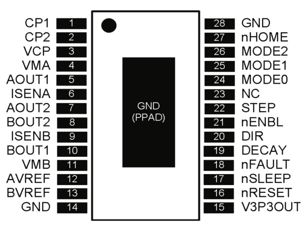
The DRV8825 stepper driver chip has a -Home output going active during the (micro)step corresponding to 45°, where both winding currents equal 71% of the peak value:
DRV8825 pinout
Unfortunately, pin 27 is another unconnected pin on the DRV8825 PCB, without even a hint of a pad for E-Z soldering.
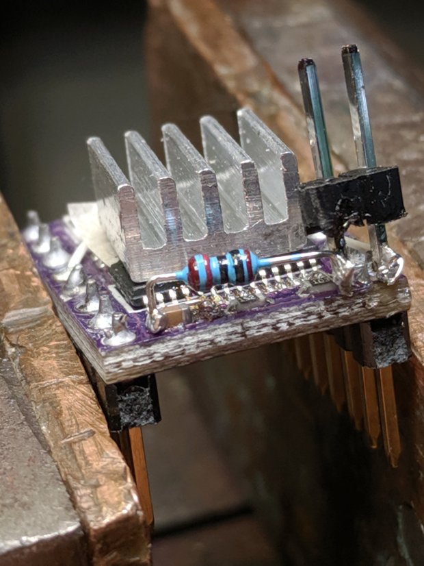
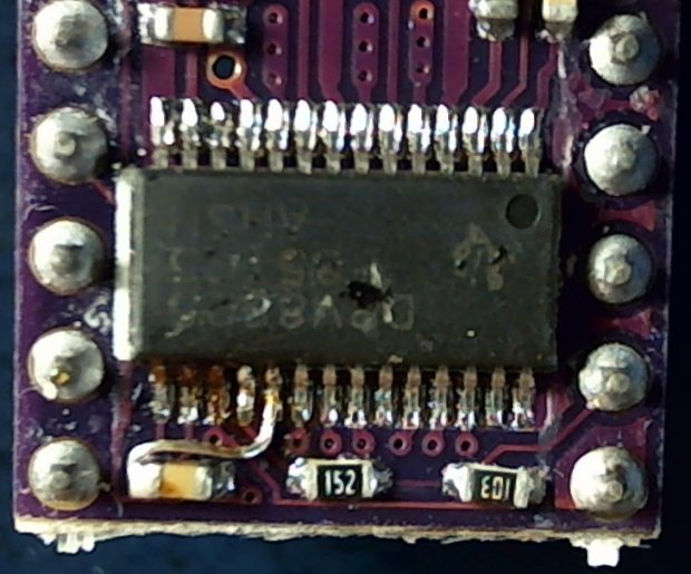
It’s also an open-drain output in need of a pullup, so I globbed on a 1/8 W 10 kΩ resistor in addition to the tiny wire from the IC pad to the left header pin:
DRV8825 PCB – Home signal output
Read it from the right: brown black black red gold. Even in person, the colors don’t look like that, not even a little bit: always measure before installation!
The right header pin is firmly soldered to the PCB ground pin I also used for the 1:8 microstep hack. The whole affair received a generous layer of hot melt glue in the hope of some mechanical stabilization, although hanging a scope probe off those pins can’t possibly end well.
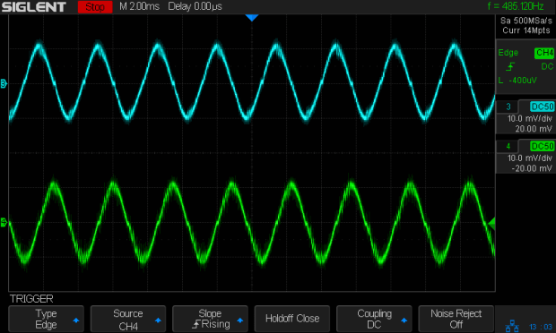
The general idea is to provide a scope sync output independent of the motor speed, so I can look at the current waveforms:
3018 X – Fast – 12V – 140mm-min 1A-div
The alert reader will note the pulse occurs on the down-going side of the waveforms, which means I have the current probes clipped on backwards or, equivalently, on the wrong wire. The point is to get a stable sync, so it’s all good no matter which way the current goes.
The CNC 3018-Pro normally holds a small DC motor with a nicely cylindrical housing,so this was an easy adaptation of the MPCNC’s diamond drag bit holder:
CNC 3018-Pro – Diamond bit – overview
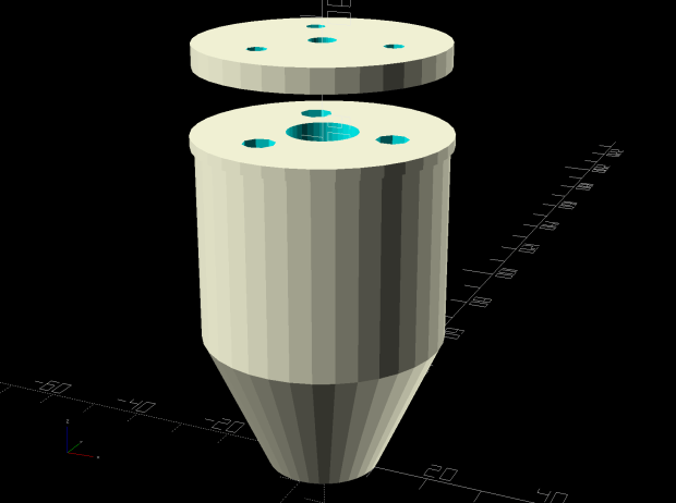
The lip around the bottom part rests atop the tool clamp, with the spring reaction plate sized to clear the notch in the Z-axis stage.
The solid model looks about like you’d expect:
Diamond Scribe – Mount – solid model
The New Thing compared to the MPCNC holder is wrapping LM6UU bearings around an actual 6 mm shaft, instead of using LM3UU bearings for the crappy diamond bit shank:
CNC 3018-Pro – Diamond bit – epoxy curing
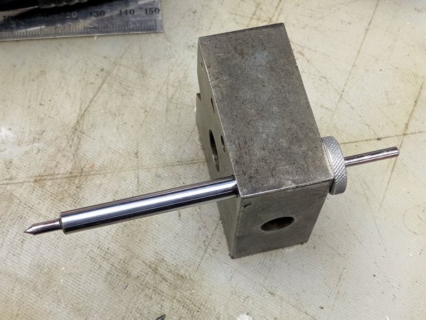
I cut the shank in two pieces, epoxied them into 3 mm holes drilled into the 6 mm shaft, then epoxied the knurled stop ring on the end. The ring is curing in the bench block to stay perpendicular to the 6 mm shaft.
The spring constant is 55 g/mm and it’s now set for 125 g preload:
CNC 3018-Pro – Diamond bit – force measurement
A quick test says all the parts have begun flying in formation:
This file contains hidden or bidirectional Unicode text that may be interpreted or compiled differently than what appears below. To review, open the file in an editor that reveals hidden Unicode characters.
Learn more about bidirectional Unicode characters
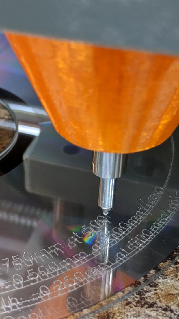
With the 3018-Pro used for drag engraving on CDs and hard drive platters, there’s no need for all the clearance below the Z-axis carriage required for the OEM motor and ER11 collet chuck. A chunk of laminate countertop and a hunk of Celotex foam insulation produce a nicely flat surface 47 mm above the platform:
CNC 3018 Table Riser
It’s surprisingly flat:
Table Flatness Measurement – 2019-08-30
Those are millimeters of clearance between the gray plastic clamp around the diamond drag tool holder (about which, more later) and my trusty bench block, measured at 50 mm intervals across the platform. The lower figures appeared after tightening the upper-left screw by a little over 1/6 turn = 0.2 mm, making the entire platform flat & aligned within ±0.1 mm.
Yeah, not bad for a scrap countertop!
The four M6 socket head cap screws pass through the stack into T-nuts in the platform:
CNC 3018 Table Riser – screw clearance
The countertop was thick enough to allow countersinking the screws slightly below the surface:
CNC 3018 Table Riser – screw countersink
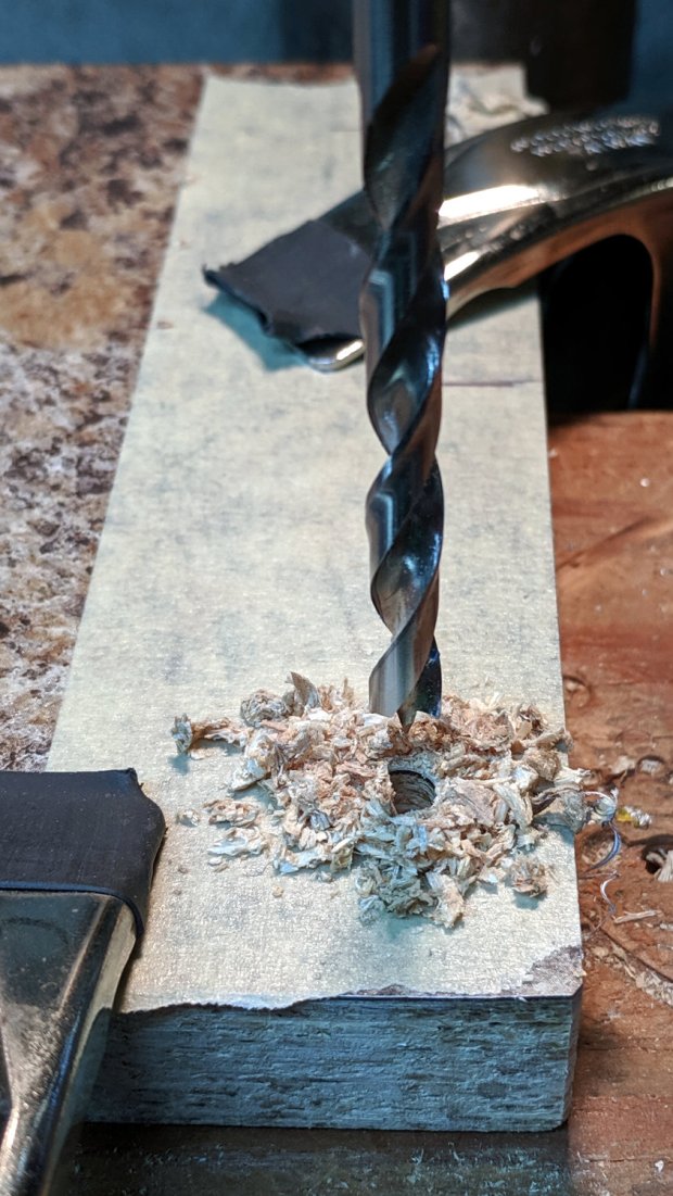
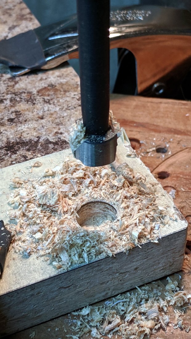
I transfer-punched the screw clearance hole locations into the Celotex and drilled it with an ordinary twist drill. It wasn’t pretty, but nobody will ever notice.
Two sheets, maybe 1 mm thick, of closed-cell foam below the Celotext provide enough squish to align the top surface without straining anything. The screws are firmly tight, so they shouldn’t work their way loose under minimal engraving loads.
Taping the CDs to the surface works well for now, although a simpler version of the fixture may be in order.
The X axis driver is an unmodified DRV8825 PCB operating in default mixed-decay mode. The Y axis DRV8825 has its DECAY pin pulled high, thereby putting it in fast decay mode.
The scope timebase varies to match the programmed feed rate. Because the X and Y axes move simultaneously, each axis moves at 1/√2 the programmed speed:
G1 X10 Y10 F100 → 71 mm/min on X and Y
The motor generates minimal back EMF at slow speeds, so the winding sees nearly the full supply voltage. As described in the previous post, the basic problem arises when the current rises too fast during each PWM cycle:
V = L di/dt
di/dt = 24 V / 3 mH = 8 kA/s
The first 1:32 microstep away from 0 calls for 5% of max current = 50 mA at a 1 A peak. The DRV8825 datasheet says the PWM typically runs at 30 kHz = 33 µs/cycle, during which the current will change by 270 mA:
267 mA = 8 kA/s × 33.3 µs
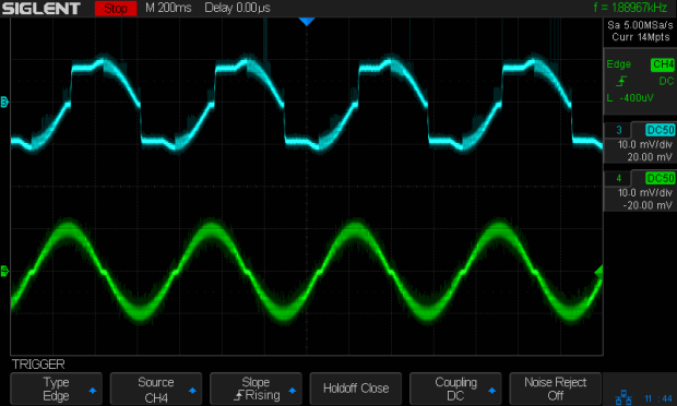
Notice how the current slams to a nearly constant, much-too-high value just after the first microstep. The incorrect current level decreases with lower supply voltage, because the rate-of-change decreases and the commanded current level reaches the actual (incorrect) current sooner.
Varying the motor voltage at a constant 10 mm/min:
3018 XY – Mixed Fast – 24V – 10mm-min 1A-div
3018 XY – Mixed Fast – 20V – 10mm-min 1A-div
3018 XY – Mixed Fast – 15V – 10mm-min 1A-div
3018 XY – Mixed Fast – 12V – 10mm-min 1A-div
3018 XY – Mixed Fast – 10V – 10mm-min 1A-div
Note that reducing the supply voltage doesn’t change the motor winding current, because the DRV8825 controls the current during each microstep, at least to the best of its ability.
Also note that the current overshoots the target for those microsteps, even when the motor is stopped, because there’s no back EMF, so the power dissipation is too high even at rest.
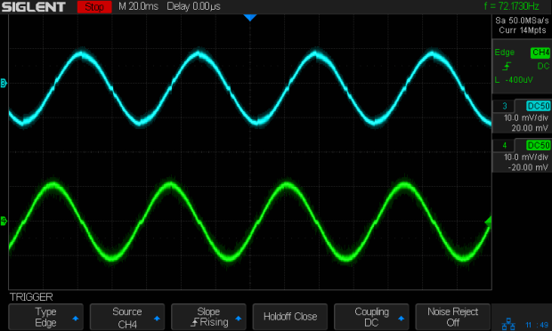
Enough back EMF appears at 100 mm/min to begin tamping down the current overshoot at 24 V:
3018 XY – Mixed Fast – 24V – 100mm-min 1A-div
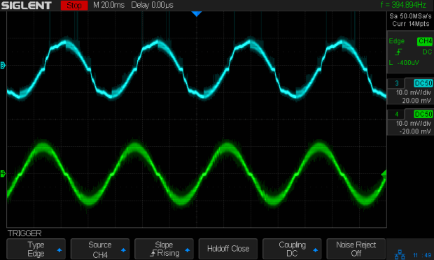
The current waveform looks good at 12 V:
3018 XY – Mixed Fast – 12V – 100mm-min 1A-div
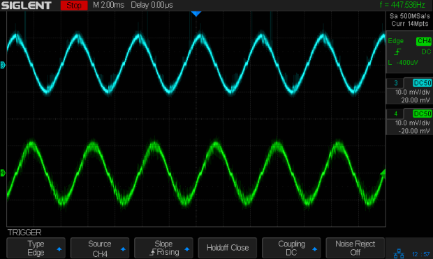
The back EMF at 1000 mm/min nearly eliminates the overshoot at 24 V, with fast decay in the Y axis causing some PWM ripple:
3018 XY – Mixed Fast – 24V – 1000mm-min 1A-div
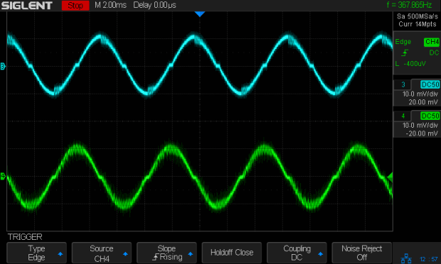
Both decay modes look good at 12 V:
3018 XY – Mixed Fast – 12V – 1000mm-min 1A-div
At 1500 mm/min, the highest reasonable speed for the thing, and a 24 V supply, both waveforms still look good:
3018 XY – Mixed Fast – 24V – 1500mm-min 1A-div
However, the back EMF is now high enough to buck the 12 V supply, preventing the current from decreasing fast enough in mixed decay mode (top trace):
3018 XY – Mixed Fast – 12V – 1500mm-min 1A-div
Tweaking the GRBL config to allow 2000 mm/min feeds shows the waveforms starting to become triangular, even at 24 V:
3018 XY – Mixed Fast – 24V – 2000mm-min 1A-div
And a 12 V supply opposed by the back EMF simply can’t change the current fast enough to keep up with the DRV8825 microstep current levels:
3018 XY – Mixed Fast – 12V – 2000mm-min 1A-div
Bottom line: a +12 V motor supply and DRV8825 drivers modified to run in fast decay mode look like the best setup for the 3018-Pro: good current control at low speeds with enough moxie to handle higher speeds.
I should hack the DRV8825 boards into 1:8 microstep mode to reduce the IRQ rate by a factor of four, then see what happens to the back EMF at absurd speeds.
Mixed decay mode begins as fast decay, but at a fixed period of time (75% of the PWM cycle) switches to slow decay mode for the remainder of the fixed PWM period. This occurs only if the current through the winding is decreasing (per the indexer step table); if the current is increasing, then slow decay is used.
The 24 V supply on the CNC 3018-Pro provides too much voltage for the motors, because slow decay mode can’t handle those rising slopes:
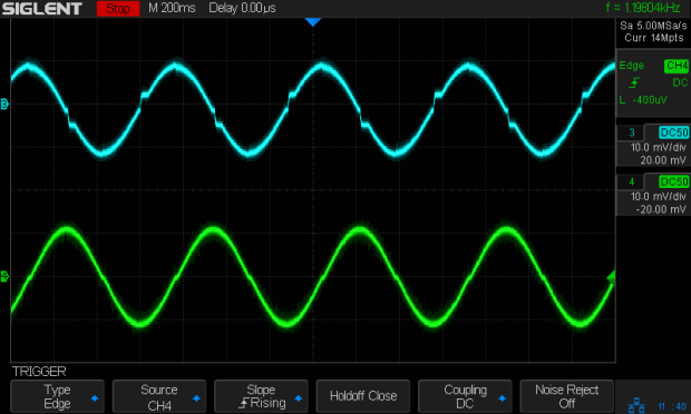
3018 XY – Mixed Fast – 24V – 10mm-min 12V 1A-div
Note that “rising” means the current increases with either polarity from 0 A at the midline. The DRV8825 uses a MOSFET H-bridge to drive winding current in either direction from the +24 V motor supply voltage.
Both traces show motor winding current at 1 A/div, with the XY axes creeping along at 10 mm/min (thus, 7.1 mm/min each). The upper trace is the X axis, with a stock DRV8825 module in mixed decay mode. The lower trace is the Y axis, with its DRV8825 hacked into fast decay mode.
The basic problem, about which more later, comes from the current rising too fast during each PWM cycle:
V = L di/dt
di/dt = 24 V / 3 mH = 8 kA/s
The first 1:32 microstep away from 0 calls for 5% of max current = 50 mA at a 1 A peak. The DRV8825 datasheet says the PWM typically runs at 30 kHz = 33 µs/cycle, during which the current will change by 270 mA:
267 mA = 8 kA/s × 33.3 µs
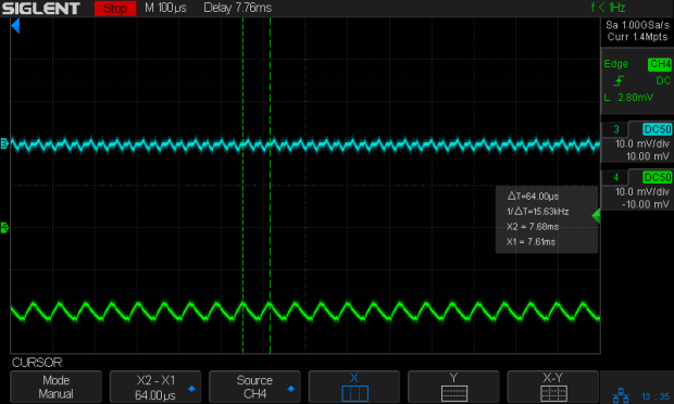
Some preliminary measurements suggest these (probably counterfeit) DRV8825 chips actually run at 16 kHz = 66 µs/cycle:
3018 X – ripple 1 step – 18V – A0 B-90 500mA-div
During those cycles the current can increase by more than 500 mA. The first scope picture shows an abrupt increase to maybe 700 mA, so, yeah, that’s about right.
Having the wrong current in one winding means the motor isn’t positioned correctly during those microsteps. The 3018-Pro runs at (an absurd) 1600 µstep/mm, so being off by even a full step isn’t big deal in terms of positioning.
The real problem comes from running nearly 1 A through both windings. Those little motors run really hot: they’re dissipating twice what they should be.
Anyhow, the pin layout shows the DRV8825 DECAY mode selection on pin 19:
DRV8825 pinout
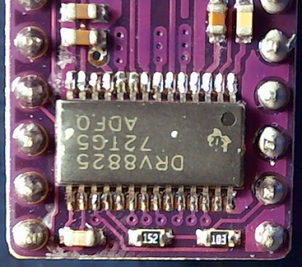
Which sits on an inconveniently skinny little PCB pad, fifth from the left on the bottom:
DRV8825 PCB – open Decay pin
Memo to Self: Don’t make that mistake when you lay out a PCB. Always put a little pad or via on a disconnected pin, so as to have a hand-soldering target big enough to work with.
The objective is to pull the pin high:
DRV8825 DECAY pin settings
Pin 15, in the lower left corner, provides the output of a 3.3 V linear regulator, with its PCB trace connected to the left side of the ceramic cap:
Those are two different PCBs. The crappy TI logos, not easily visible in those low-res pix, on both ICs suggest they’re by-now-typical counterfeits, so seeing a factor-of-two difference in PWM frequency isn’t surprising.
The CNC 3018-Pro router arrived with GRBL 1.1f installed on the Camtool V3.3 board and ran well enough, although it accelerated very slowly. After installing Home switches, figuring out the travel limits, and trying different speeds & accelerations, it runs much better:
$1=100 turns off the stepper motor drivers after 100 ms of inactivity:
3018 X – 100ms timeout – 100mm-min 12V 500 ma-div
There’s no force worth mentioning on a diamond scribe when the motors stop, so there’s no reason to keep them energized, and the DRV8825 chips resume from the same microstep when re-enabled.
$3=5 reverses the X and Z motor rotation, so you can use the same type of cable on all three axes and have them move the way you’d expect.
$20=1 turns on Soft Limits, thereby producing an error when you (or the G-Code) tries to move beyond the machine’s limits, as defined by the $120 $121 $122 values relative to the Home switch positions.
$21=0 leaves Hard Limits off, because I didn’t see much point in switches on both ends of all the axes for this little bitty machine.
$22=1 enables the Home cycle, after which you must start each session by homing the machine.
$27=1.000 sets the Pull-off distance from all three Home positions, so the machine ends up at absolute XYZ = -1.000 mm relative to the switch trip points after homing. This depends on the mechanics of the limit switches, but seems OK with the MBI-style switches I used:
$110 $111 $112 = 1100 set the maximum speed along the XYZ axes in mm/min. Note the hard upper limit set by the maximum microcontroller interrupt rate of about 40 k/s:
I’ll have more to say about speed limits, stepper current, torque, and similar topics.
$120 $121 $122 = 3000 set the acceleration along the XYZ axes in mm/sec². These are two orders of magnitude higher than the default acceleration, which accounts for the as-received sluggish acceleration.
$130=299.000 $131=179.000 $132=44.000 set the XYZ travel limits relative to the Home switch trip points, which feed into the $20=1 Soft Limits. You could probably eke out another millimeter along each axis, but this is what I came up with.
With all those in place, the G54 coordinate system puts the XY origin dead in the middle of the platform and the Z origin a little bit below its upper travel limit. Set them thusly:
G10 L2 P1 X-147 Y-90.6 Z-1.5
The original and tweaked GRBL configuration settings as a GitHub Gist:
This file contains hidden or bidirectional Unicode text that may be interpreted or compiled differently than what appears below. To review, open the file in an editor that reveals hidden Unicode characters.
Learn more about bidirectional Unicode characters
This file contains hidden or bidirectional Unicode text that may be interpreted or compiled differently than what appears below. To review, open the file in an editor that reveals hidden Unicode characters.
Learn more about bidirectional Unicode characters
My collection of old USB cameras emitted a Logitech Quickcam for Notebooks Deluxe, with a tag giving a cryptic M/N of V-UGB35. Given Logitech’s penchant for overlapping names, its USB identifiers may be more useful for positive ID:
ID 046d:08d8 Logitech, Inc. QuickCam for Notebook Deluxe
It works fine as a simple V4L camera and its 640×480 optical resolution may suffice for simple purposes, even if it’s not up to contemporary community standards.
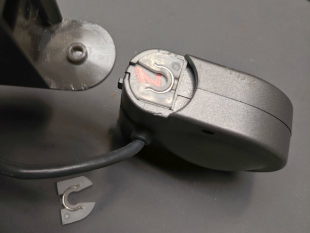
The key disassembly step turned out to be simply pulling the pivoting base off, then recovering an errant spring clip from the Laboratory Floor:
Logitech V-UGB35 USB Camera – mount removed
The clips have a beveled side and fit into their recesses in only one orientation; there’s no need for brute force.
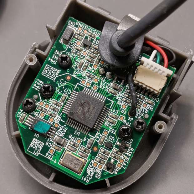
Removing the two obvious case screws reveals the innards:
Logitech V-UGB35 USB Camera – PCB rear
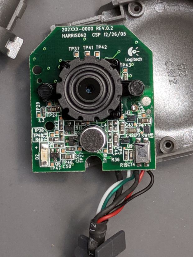
Three more screws secure the PCB:
Logitech V-UGB35 USB Camera – PCB front
The ribbed focus knob around the lens makes it more useful than a nominally fixed-focus camera.