The Smell of Molten Projects in the Morning

Ed Nisley's Blog: Shop notes, electronics, firmware, machinery, 3D printing, laser cuttery, and curiosities. Contents: 100% human thinking, 0% AI slop.

Tag: CNC-3018XL

Small gantry router

  • CNC 3018-Pro: Platter Fixtures

    Up to this point, the Sherline has been drilling 3.5 inch hard drive platters to serve as as reflecting bases for the vacuum tubes:

    LinuxCNC - Sherline Mill - Logitech Gamepad
    LinuxCNC – Sherline Mill – Logitech Gamepad

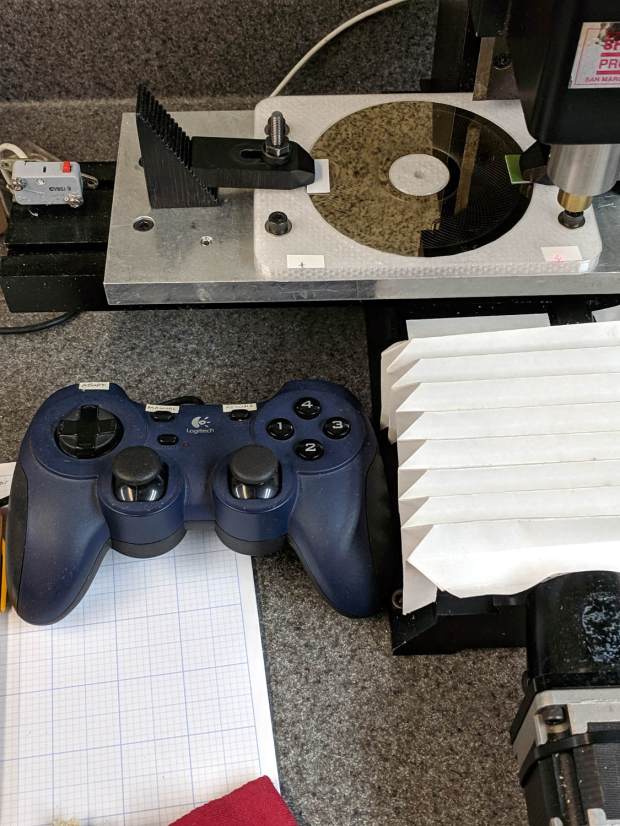
    The CNC 3018-Pro has a work envelope large enough for CD / DVD platters, so I mashed the Sherline fixture with dimensions from the vacuum tube code, added the 3018’s T-slot spacing, and conjured a pair of fixtures for a pair of machines.

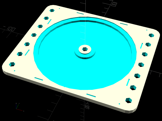
    Because I expect to practice on scrap CDs and DVDs for a while:

    Platter Fixtures - CD on 3018
    Platter Fixtures – CD on 3018

    And a 3.5 inch hard drive platter version:

    Platter Fixtures - hard drive platter on 3018
    Platter Fixtures – hard drive platter on 3018

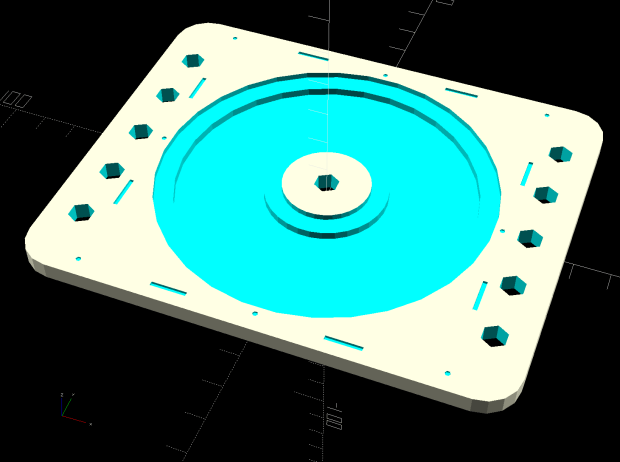
    The holes sit at half the 3018’s T-slot spacing (45 mm / 2), so you can nudge the fixtures to the front or rear, as you prefer.

    The alignment dots & slots should help touch off the XY coordinate system on the Sherline, although it can’t reach all of a CD. Using bCNC’s video alignment on the hub hole will be much easier on the 3018.

    After fiddling around with the 3018 for a while, however, the CD fixture doesn’t have many advantages over simply taping the disc to a flat platen. Obviously, you’d want a sacrificial layer for drilling, but it’s not clear the OEM motor / ER11 chuck would be up to that task.

    The OpenSCAD source code as a GitHub Gist:

    // Machining fixtures for CD and hard drive platters
    // Ed Nisley KE4ZNU February … September 2016
    // 2019-08 split from tube base models
    PlatterName = "CD"; // [3.5inch,CD]
    CNCName = "3018"; // [3018,Sherline]
    PlateThick = 5.0; // [5.0,10.0,15.0]
    RecessDepth = 4.0; // [0.0,2.0,4.0]
    //- Extrusion parameters must match reality!
    /* [Hidden] */
    ThreadThick = 0.25;
    ThreadWidth = 0.40;
    HoleWindage = 0.2;
    Protrusion = 0.1; // make holes end cleanly
    inch = 25.4;
    function IntegerMultiple(Size,Unit) = Unit * ceil(Size / Unit);
    module PolyCyl(Dia,Height,ForceSides=0) { // based on nophead's polyholes
    Sides = (ForceSides != 0) ? ForceSides : (ceil(Dia) + 2);
    FixDia = Dia / cos(180/Sides);
    cylinder(d=(FixDia + HoleWindage),h=Height,$fn=Sides);
    }
    ID = 0;
    OD = 1;
    LENGTH = 2;
    //———————-
    // Dimensions
    P_NAME = 0; // platter name
    P_ID = 1; // … inner diameter
    P_OD = 2; // … outer diameter
    P_THICK = 3; // … thickness
    PlatterData = [
    ["3.5inch", 25.0, 95.0, 1.75],
    ["CD", 15.0, 120.0, 1.20],
    ];
    PlatterSides = 3*4*5; // polygon approximation
    B_NAME = 0; // machine name
    B_OC = 1; // … platform screw OC, use small integer for slot
    B_STUD = 2; // … screw OD clearance
    BaseData = [
    ["3018", [5.0, 45.0], 6.0], // slots along X axis
    ["Sherline", [1.16*inch,1.16*inch], 5.0], // tooling plate
    ];
    //———————-
    // Drilling fixture for disk platters
    module PlatterFixture(Disk,Machine) {
    PI = search([Disk],PlatterData,1,0)[P_NAME]; // get platter index
    echo(str("Platter: ",Disk));
    Platter = [PlatterData[PI][P_ID],
    PlatterData[PI][P_OD],
    PlatterData[PI][P_THICK]];
    BI = search([Machine],BaseData,1,0)[B_NAME]; // get base index
    echo(str("Machine: ",Machine));
    AlignOC = IntegerMultiple(Platter[OD],10);
    echo(str("Align OC: ",AlignOC));
    AlignSlot = [3*ThreadWidth,10.0,3*ThreadThick];
    StudClear = BaseData[BI][B_STUD]; // … clearance
    StudOC = [IntegerMultiple(AlignOC + 2*StudClear,BaseData[BI][B_OC].x), // … screw spacing
    BaseData[BI][B_OC].y];
    echo(str("Stud spacing: ",StudOC));
    NumStuds = [2,1 + 2*floor(Platter[OD] / StudOC.y)]; // holes only along ±X edges
    echo(str("Stud holes: ",NumStuds));
    BasePlate = [(20 + StudOC.x*ceil(Platter[OD] / StudOC.x)),
    (10 + AlignOC),
    PlateThick];
    echo(str("Plate: ",BasePlate));
    PlateRound = 10.0; // corner radius
    difference() {
    hull() // basic plate shape
    for (i=[-1,1], j=[-1,1])
    translate([i*(BasePlate.x/2 – PlateRound),j*(BasePlate.y/2 – PlateRound),0])
    cylinder(r=PlateRound,h=BasePlate.z,$fn=4*4);
    for (i=[-1,0,1], j=[-1,0,1]) // origin pips
    translate([i*AlignOC/2,j*AlignOC/2,BasePlate.z – 2*ThreadThick])
    cylinder(d=4*ThreadWidth,h=1,$fn=6);
    for (i=[-1,1], j=[-1,1]) { // alignment slots
    translate([i*(AlignOC + AlignSlot.x)/2,
    j*Platter[OD]/4,
    (BasePlate.z – AlignSlot.z/2 + Protrusion/2)])
    cube(AlignSlot + [0,0,Protrusion],center=true);
    translate([i*Platter[OD]/4,
    j*(AlignOC + AlignSlot.x)/2,
    (BasePlate.z – AlignSlot.z/2 + Protrusion/2)])
    rotate(90)
    cube(AlignSlot + [0,0,Protrusion],center=true);
    }
    for (i=[-1,1], j=[-floor(NumStuds.y/2):floor(NumStuds.y/2)]) // mounting stud holes
    translate([i*StudOC.x/2,j*StudOC.y/2,-Protrusion])
    rotate(180/6)
    PolyCyl(StudClear,BasePlate.z + 2*Protrusion,6);
    translate([0,0,-Protrusion]) // center clamp hole
    rotate(180/6)
    PolyCyl(StudClear,BasePlate.z + 2*Protrusion,6);
    translate([0,0,BasePlate.z – Platter[LENGTH]]) // disk locating recess
    rotate(180/PlatterSides)
    linear_extrude(height=(Platter[LENGTH] + Protrusion),convexity=2)
    difference() {
    circle(d=(Platter[OD] + HoleWindage),$fn=PlatterSides);
    circle(d=Platter[ID] – HoleWindage,$fn=PlatterSides);
    }
    translate([0,0,BasePlate.z – RecessDepth]) // drilling recess
    rotate(180/PlatterSides)
    linear_extrude(height=(RecessDepth + Protrusion),convexity=2)
    difference() {
    circle(d=(Platter[OD] – 10),$fn=PlatterSides);
    circle(d=(Platter[ID] + 10),$fn=PlatterSides);
    }
    }
    }
    //———————-
    // Build it
    PlatterFixture(PlatterName,CNCName);
  • CNC 3018-Pro: DRV8825 Hack for 1:8 Microstep Mode

    The CAMTool V3.3 board on the CNC 3018-Pro hardwires the three DRV8825 stepper driver chips in 1:32 microstep mode by pulling all three Mode pins high. Unlike most CNC boards, it does not include jumpers to let you select different microstep modes; the designers know you want as many microsteps as you can possibly get.

    As it turns out, 1:32 microstep mode requires 1600 steps for each millimeter of travel and, because GRBL tops out around 30 k step/s, the maximum speed is about 18.75 mm/s = 1125 mm/min. Which isn’t at bad, but, because I intend to use the thing for engraving, rather than the light-duty machining it’s (allegedly) capable of performing, running at somewhat higher speeds will be desirable.

    For sure, a 3018-Pro does not have a physical resolution of 625 nm.

    If you’re willing to settle for a mere 400 step/mm = 2.6 µm, then you can just ground the Mode 2 pin to get 1:8 microstep mode:

    DRV8825 - Stepper Motor Controller - Microstep Modes
    DRV8825 – Stepper Motor Controller – Microstep Modes

    Rewiring the CAMTool board isn’t feasible, but hacking the DRV8825 carrier PCB doesn’t require much effort.

    So, we begin.

    Clamp the PCB in a vise, grab the Mode 2 pin with a needle-nose pliers, apply enough heat to melt the solder completely through the board, and yank that pin right out:

    CAMTool V3.3 - DRV8825 M2 pin removed
    CAMTool V3.3 – DRV8825 M2 pin removed

    I do wonder how the layout folks managed to reverse the “N” for the Enable pin. Perhaps it’s a Cyrillic И in a dead-simple font?

    With that done, add a snippet of wire from M2 to the GND pin in the opposite corner to complete the job:

    CAMTool V3.3 - DRV8825 wired for 8 ustep mode
    CAMTool V3.3 – DRV8825 wired for 8 ustep mode

    Despite that picture, remember to plug the DRV8825 boards into the CAMTool V3.3 board with the heatsink downward and the twiddlepot on the top, as shown in the little instruction book you got with the hardware:

    SainSmart Genmitsu CNC Router 3018PRO-User Manual - DRV8825 orientation
    SainSmart Genmitsu CNC Router 3018PRO-User Manual – DRV8825 orientation

    Recompute the step/mm value in 1:8 microstep mode:

    400 step/mm = (200 full step/rev) × (8 microstep/full step) / (4 mm/rev)

    Then set the corresponding GRBL parameters:

    $100=400
    $101=400
    $102=400

    The 3018-Pro should work exactly like it did before, maybe a little noisier if your ears are up to the task.

    Moah Speed comes later …

  • CNC 3018-Pro: CAMTool V3.3 USB Power Diode

    The CAMTool V3.3 board dispenses with fancy USB power switching circuitry:

    CAMTOOL CNC-V3.3 schematic - USB Power Entry
    CAMTOOL CNC-V3.3 schematic – USB Power Entry

    The NUP2201 is an ESD clamp diode / suppressor IC, which is a nice touch, but FU1, a simple 300 mA polyfuse, is the only thing standing between the USB cable and the on-board +5 V regulator. In real life, it looks like this:

    CAMTool V3.3 - USB power fuse
    CAMTool V3.3 – USB power fuse

    It’s the little black rectangle between the USB jack and the CH340 USB-to-serial chip. The

    The far end of the USB cable plugs into a Raspberry Pi, a device known for unseemly fussiness about USB power, so I unsoldered the fuse and installed a diode:

    CAMTool V3.3 - USB power diode
    CAMTool V3.3 – USB power diode

    It’s a BAT54 Schottky diode, pointed toward the right to prevent current from the board getting to the Pi. Pin 2 (toward the bottom) isn’t connected to anything inside the package, either, so it’s all good.

    I suppose if one were a stickler for detail, one could gimmick the diode in series with the fuse, but I figured that’s a solution for a problem well down on the probability list …

  • DRV8825 Stepper Driver: Fast vs. Mixed Decay Current Waveforms

    Herewith, a look at CNC 3018-Pro stepper motor current waveforms as a function of supply voltage, PWM decay mode, and motor speed.

    The scope displays X and Y axis motor current at 1 A/div, with sensing through a pair of Tektronix Hall effect current probes:

    CNC 3018-Pro - XY axes - Tek current probes
    CNC 3018-Pro – XY axes – Tek current probes

    The X axis driver is an unmodified DRV8825 PCB operating in default mixed-decay mode. The Y axis DRV8825 has its DECAY pin pulled high, thereby putting it in fast decay mode.

    The scope timebase varies to match the programmed feed rate. Because the X and Y axes move simultaneously, each axis moves at 1/√2 the programmed speed:

    G1 X10 Y10 F100 → 71 mm/min on X and Y

    The motor generates minimal back EMF at slow speeds, so the winding sees nearly the full supply voltage. As described in the previous post, the basic problem arises when the current rises too fast during each PWM cycle:

    V = L di/dt
    di/dt = 24 V / 3 mH = 8 kA/s

    The first 1:32 microstep away from 0 calls for 5% of max current = 50 mA at a 1 A peak. The DRV8825 datasheet says the PWM typically runs at 30 kHz = 33 µs/cycle, during which the current will change by 270 mA:

    267 mA = 8 kA/s × 33.3 µs

    Notice how the current slams to a nearly constant, much-too-high value just after the first microstep. The incorrect current level decreases with lower supply voltage, because the rate-of-change decreases and the commanded current level reaches the actual (incorrect) current sooner.

    Varying the motor voltage at a constant 10 mm/min:

    3018 XY - Mixed Fast - 24V - 10mm-min 1A-div
    3018 XY – Mixed Fast – 24V – 10mm-min 1A-div
    3018 XY - Mixed Fast - 20V - 10mm-min 1A-div
    3018 XY – Mixed Fast – 20V – 10mm-min 1A-div
    3018 XY - Mixed Fast - 15V - 10mm-min 1A-div
    3018 XY – Mixed Fast – 15V – 10mm-min 1A-div
    3018 XY - Mixed Fast - 12V - 10mm-min 1A-div
    3018 XY – Mixed Fast – 12V – 10mm-min 1A-div
    3018 XY - Mixed Fast - 10V - 10mm-min 1A-div
    3018 XY – Mixed Fast – 10V – 10mm-min 1A-div

    Note that reducing the supply voltage doesn’t change the motor winding current, because the DRV8825 controls the current during each microstep, at least to the best of its ability.

    Also note that the current overshoots the target for those microsteps, even when the motor is stopped, because there’s no back EMF, so the power dissipation is too high even at rest.

    Enough back EMF appears at 100 mm/min to begin tamping down the current overshoot at 24 V:

    3018 XY - Mixed Fast - 24V - 100mm-min 1A-div
    3018 XY – Mixed Fast – 24V – 100mm-min 1A-div

    The current waveform looks good at 12 V:

    3018 XY - Mixed Fast - 12V - 100mm-min 1A-div
    3018 XY – Mixed Fast – 12V – 100mm-min 1A-div

    The back EMF at 1000 mm/min nearly eliminates the overshoot at 24 V, with fast decay in the Y axis causing some PWM ripple:

    3018 XY - Mixed Fast - 24V - 1000mm-min 1A-div
    3018 XY – Mixed Fast – 24V – 1000mm-min 1A-div

    Both decay modes look good at 12 V:

    3018 XY - Mixed Fast - 12V - 1000mm-min 1A-div
    3018 XY – Mixed Fast – 12V – 1000mm-min 1A-div

    At 1500 mm/min, the highest reasonable speed for the thing, and a 24 V supply, both waveforms still look good:

    3018 XY - Mixed Fast - 24V - 1500mm-min 1A-div
    3018 XY – Mixed Fast – 24V – 1500mm-min 1A-div

    However, the back EMF is now high enough to buck the 12 V supply, preventing the current from decreasing fast enough in mixed decay mode (top trace):

    3018 XY - Mixed Fast - 12V - 1500mm-min 1A-div
    3018 XY – Mixed Fast – 12V – 1500mm-min 1A-div

    Tweaking the GRBL config to allow 2000 mm/min feeds shows the waveforms starting to become triangular, even at 24 V:

    3018 XY - Mixed Fast - 24V - 2000mm-min 1A-div
    3018 XY – Mixed Fast – 24V – 2000mm-min 1A-div

    And a 12 V supply opposed by the back EMF simply can’t change the current fast enough to keep up with the DRV8825 microstep current levels:

    3018 XY - Mixed Fast - 12V - 2000mm-min 1A-div
    3018 XY – Mixed Fast – 12V – 2000mm-min 1A-div

    Bottom line: a +12 V motor supply and DRV8825 drivers modified to run in fast decay mode look like the best setup for the 3018-Pro: good current control at low speeds with enough moxie to handle higher speeds.

    I should hack the DRV8825 boards into 1:8 microstep mode to reduce the IRQ rate by a factor of four, then see what happens to the back EMF at absurd speeds.

  • DRV8825 Stepper Driver: Forcing Fast Decay Mode in a (Likely) Counterfeit Chip

    The DRV8825 stepper driver chip defaults to mixed decay mode, which TI defines thusly:

    Mixed decay mode begins as fast decay, but at a fixed period of time (75% of the PWM cycle) switches to slow decay mode for the remainder of the fixed PWM period. This occurs only if the current through the winding is decreasing (per the indexer step table); if the current is increasing, then slow decay is used.

    The 24 V supply on the CNC 3018-Pro provides too much voltage for the motors, because slow decay mode can’t handle those rising slopes:

    3018 XY - Mixed Fast - 24V - 10mm-min 12V 1A-div
    3018 XY – Mixed Fast – 24V – 10mm-min 12V 1A-div

    Note that “rising” means the current increases with either polarity from 0 A at the midline. The DRV8825 uses a MOSFET H-bridge to drive winding current in either direction from the +24 V motor supply voltage.

    Both traces show motor winding current at 1 A/div, with the XY axes creeping along at 10 mm/min (thus, 7.1 mm/min each). The upper trace is the X axis, with a stock DRV8825 module in mixed decay mode. The lower trace is the Y axis, with its DRV8825 hacked into fast decay mode.

    The basic problem, about which more later, comes from the current rising too fast during each PWM cycle:

    V = L di/dt
    di/dt = 24 V / 3 mH = 8 kA/s

    The first 1:32 microstep away from 0 calls for 5% of max current = 50 mA at a 1 A peak. The DRV8825 datasheet says the PWM typically runs at 30 kHz = 33 µs/cycle, during which the current will change by 270 mA:

    267 mA = 8 kA/s × 33.3 µs

    Some preliminary measurements suggest these (probably counterfeit) DRV8825 chips actually run at 16 kHz = 66 µs/cycle:

    3018 X - ripple 1 step - 18V - A0 B-90 500mA-div
    3018 X – ripple 1 step – 18V – A0 B-90 500mA-div

    During those cycles the current can increase by more than 500 mA. The first scope picture shows an abrupt increase to maybe 700 mA, so, yeah, that’s about right.

    Having the wrong current in one winding means the motor isn’t positioned correctly during those microsteps. The 3018-Pro runs at (an absurd) 1600 µstep/mm, so being off by even a full step isn’t big deal in terms of positioning.

    The real problem comes from running nearly 1 A through both windings. Those little motors run really hot: they’re dissipating twice what they should be.

    Anyhow, the pin layout shows the DRV8825 DECAY mode selection on pin 19:

    DRV8825 pinout
    DRV8825 pinout

    Which sits on an inconveniently skinny little PCB pad, fifth from the left on the bottom:

    DRV8825 PCB - open Decay pin
    DRV8825 PCB – open Decay pin

    Memo to Self: Don’t make that mistake when you lay out a PCB. Always put a little pad or via on a disconnected pin, so as to have a hand-soldering target big enough to work with.

    The objective is to pull the pin high:

    DRV8825 DECAY pin settings
    DRV8825 DECAY pin settings

    Pin 15, in the lower left corner, provides the output of a 3.3 V linear regulator, with its PCB trace connected to the left side of the ceramic cap:

    DRV8825 PCB - Decay pin wired low
    DRV8825 PCB – Decay pin wired low

    On the scale of TSSOP packages, even 30 AWG Wire-Wrap wire looks like a bus bar!

    Those are two different PCBs. The crappy TI logos, not easily visible in those low-res pix, on both ICs suggest they’re by-now-typical counterfeits, so seeing a factor-of-two difference in PWM frequency isn’t surprising.

  • CNC 3018-Pro: GRBL Configuration

    The CNC 3018-Pro router arrived with GRBL 1.1f installed on the Camtool V3.3 board and ran well enough, although it accelerated very slowly. After installing Home switches, figuring out the travel limits, and trying different speeds & accelerations, it runs much better:

    3018 CNC - Endstop switches - overview
    3018 CNC – Endstop switches – overview

    Configuration values to remember for next time:

    $1=100 turns off the stepper motor drivers after 100 ms of inactivity:

    3018 X - 100ms timeout - 100mm-min 12V 500 ma-div
    3018 X – 100ms timeout – 100mm-min 12V 500 ma-div

    There’s no force worth mentioning on a diamond scribe when the motors stop, so there’s no reason to keep them energized, and the DRV8825 chips resume from the same microstep when re-enabled.

    $3=5 reverses the X and Z motor rotation, so you can use the same type of cable on all three axes and have them move the way you’d expect.

    $20=1 turns on Soft Limits, thereby producing an error when you (or the G-Code) tries to move beyond the machine’s limits, as defined by the $120 $121 $122 values relative to the Home switch positions.

    $21=0 leaves Hard Limits off, because I didn’t see much point in switches on both ends of all the axes for this little bitty machine.

    $22=1 enables the Home cycle, after which you must start each session by homing the machine.

    $27=1.000 sets the Pull-off distance from all three Home positions, so the machine ends up at absolute XYZ = -1.000 mm relative to the switch trip points after homing. This depends on the mechanics of the limit switches, but seems OK with the MBI-style switches I used:

    3018 CNC - X axis endstop - 1 mm pull-off
    3018 CNC – X axis endstop – 1 mm pull-off

    $100 $101 $102 = 1600 set the XYZ step/mm, which requires knowing the 3018-Pro uses two-start leadscrews with a 2 mm pitch = 4 mm lead:

    3018 CNC - two-start leadscrew
    3018 CNC – two-start leadscrew

    The Camtool V3.3 board hardwires the DRV8825 stepper controllers into 32 microstep mode, so:

    1600 step/mm = (200 full step/rev) × (32 microstep/full step) / (4 mm/rev)

    $110 $111 $112 = 1100 set the maximum speed along the XYZ axes in mm/min. Note the hard upper limit set by the maximum microcontroller interrupt rate of about 40 k/s:

    1500 mm/min = 25 mm/s = (40×10³ step/s) / (1600 step/mm)

    I’ll have more to say about speed limits, stepper current, torque, and similar topics.

    $120 $121 $122 = 3000 set the acceleration along the XYZ axes in mm/sec². These are two orders of magnitude higher than the default acceleration, which accounts for the as-received sluggish acceleration.

    $130=299.000 $131=179.000 $132=44.000 set the XYZ travel limits relative to the Home switch trip points, which feed into the $20=1 Soft Limits. You could probably eke out another millimeter along each axis, but this is what I came up with.

    With all those in place, the G54 coordinate system puts the XY origin dead in the middle of the platform and the Z origin a little bit below its upper travel limit. Set them thusly:

    G10 L2 P1 X-147 Y-90.6 Z-1.5

    The original and tweaked GRBL configuration settings as a GitHub Gist:

    $0=10
    $1=25
    $2=0
    $3=5
    $4=0
    $5=0
    $6=0
    $10=1
    $11=0.010
    $12=0.002
    $13=0
    $20=0
    $21=0
    $22=0
    $23=0
    $24=25.000
    $25=500.000
    $26=250
    $27=1.000
    $30=1000
    $31=0
    $32=0
    $100=1600.000
    $101=1600.000
    $102=1600.000
    $110=1000.000
    $111=1000.000
    $112=800.000
    $120=30.000
    $121=30.000
    $122=30.000
    $130=200.000
    $131=200.000
    $132=200.000
    $0=10
    $1=100
    $2=0
    $3=5
    $4=0
    $5=0
    $6=0
    $10=1
    $11=0.010
    $12=0.020
    $13=0
    $20=1
    $21=0
    $22=1
    $23=0
    $24=100.000
    $25=1000.000
    $26=25
    $27=1.000
    $30=1000
    $31=0
    $32=0
    $100=1600.000
    $101=1600.000
    $102=1600.000
    $110=1100.000
    $111=1100.000
    $112=1100.000
    $120=3000.000
    $121=3000.000
    $122=3000.000
    $130=299.000
    $131=179.000
    $132=44.000
    ok
    [G54:-147.000,-90.600,-1.500]
    [G55:0.000,0.000,0.000]
    [G56:0.000,0.000,0.000]
    [G57:0.000,0.000,0.000]
    [G58:0.000,0.000,0.000]
    [G59:0.000,0.000,0.000]
    [G28:0.000,0.000,0.000]
    [G30:0.000,0.000,0.000]
    [G92:0.000,0.000,0.000]
    [TLO:0.000]
    [PRB:0.000,0.000,0.000:0]
    ok

    The as-shipped configuration is mostly for reference, but ya never know when it might come in handy.

  • Logitech “QuickCam Pro 5000” Ball Camera Disassembly

    Another alignment camera contestant from the Big Box o’ Junk Cameras:

    Logitech Pro 5000 Ball Camera - overview
    Logitech Pro 5000 Ball Camera – overview

    It’s a Logitech QuickCam Pro 5000 with a native 640×480 resolution. For no obvious reason, it seems to work better on a Raspberry Pi than the Logitech QuickCam for Notebooks Deluxe I ripped apart a few weeks ago, where “better” is defined as “shows a stable image”. I have no explanation for anything.

    Remove the weird bendy foot-like object by pulling straight out, then remove the single screw from the deep hole visible just behind the dent in the top picture:

    Logitech Pro 5000 Ball Camera - disassembled
    Logitech Pro 5000 Ball Camera – disassembled

    The stylin’ curved plate on the top holds the microphone and a button, neither of which will be of use in its future life. Unplug and discard, leaving the USB cable as the only remaining connection:

    Logitech Pro 5000 Ball Camera - USB connector
    Logitech Pro 5000 Ball Camera – USB connector

    Inexplicably, the cable shield is soldered to the PCB, so the connector doesn’t do much good. Hack the molded ball off of the cable with a diagonal cutter & razor knife, taking more care than I did to not gouge the cable insulation.

    A glue dot locks the focusing threads:

    Logitech Pro 5000 Ball Camera - focus glue
    Logitech Pro 5000 Ball Camera – focus glue

    Gentle suasion with a needle nose pliers pops the dot, leaving the lens free to focus on objects much closer than infinity:

    Logitech QuickCam Pro 5000 - short focus
    Logitech QuickCam Pro 5000 – short focus

    Now, to conjure a simpleminded mount …