Ed Nisley's Blog: Shop notes, electronics, firmware, machinery, 3D printing, laser cuttery, and curiosities. Contents: 100% human thinking, 0% AI slop.
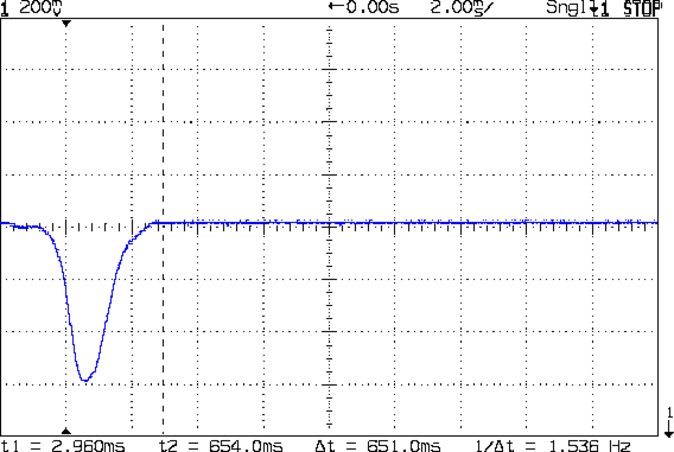
The blip comes from the shaft of a small screwdriver falling through the beam.
That’s in photovoltaic mode directly connected to the oscilloscope, but you’d want to run it through a low-gain transimpedance amplifier to get the zero bias photocurrent and a comparator for a clean digital edge. That’s obviously overkill for a simple optical interrupter, but the analog circuitry should come in handy for something else later on.
OK, now I can detect a moving object, trigger a camera, and fire a xenon flash, all under an Arduino’s control…
The CHDK firmware for Canon point-and-shoot cameras includes a USB remote trigger feature that depends on simply applying +5 V to the USB power leads, which is exactly what happens when you plug an ordinary USB cable into a PC.
Chopping up a spare cable, adding header pins, attaching a bench supply, and whacking the pins with clip leads showed that the camera takes quite a while to haul itself to its feet and click the shutter:
Canon SX230HS – USB trigger – flash
That’s with:
Manual mode: preset shutter & aperture
Manual focus
Focus assist off
Image stabilization off
AF guide light off
Red eye reduction off
Flash enabled, medium intensity, precharged
Turning the flash off slightly reduces the delay, at least judging from when I hear the shutter click while watching the trace trundle across the screen. I may have forgotten to turn something else off, but I doubt it’ll get an order of magnitude faster.
I’d hoped to synchronize an outboard flash with the shutter, but watching a few traces shows that the time from trigger to flash isn’t very consistent; maybe 100 ms jitter, more or less.
The CHDK motion-sensing script works and is “lightning fast”, but it turns out that lightning strokes actually glow for tens to hundreds of milliseconds, so my 1 ms xenon flash will be over and done with by the time the script reacts and opens the camera shutter.
Other ways to synchronize an outboard flash with the shutter:
Fire the outboard flash from the camera flash, with the camera flash inside a shield
Use an absurdly long shutter time with the camera & objects inside a very, very dark enclosure
Use the CHDK motion detection script, but blink an LED into the lens to trigger the shutter, then fire the xenon flash to expose the image
Choice 1 has positive synchronization to the camera shutter, but the shutter delay jitter means the flash won’t happen after a fixed delay from the triggering event. Maybe it’s not as bad as I think.
Choice 2 requires that the shutter stay open longer than the maximum delay jitter, so the flash will happen at known time after the triggering event. I like that, but not the dark enclosure part.
Choice 3 depends on the timing jitter of the script, which should be on the order of a few tens of milliseconds. A shutter speed of 1/25 s = 40 ms might be Good Enough.
This obviously requires a bit of Arduino fiddling…
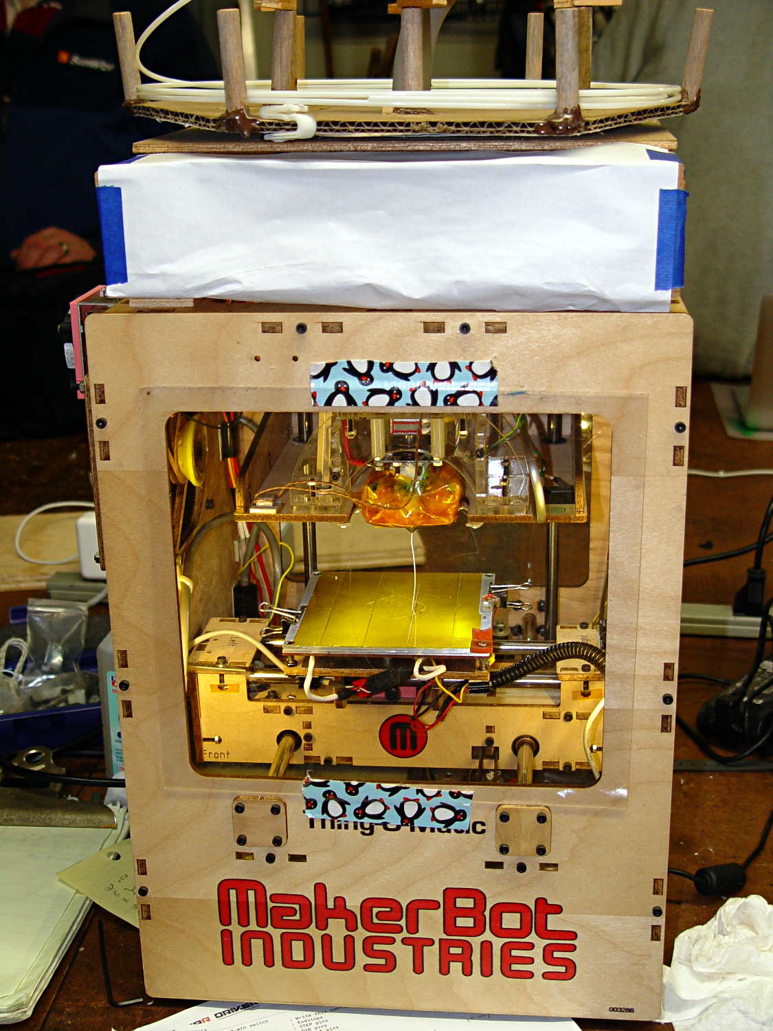
My old Thing-O-Matic has new life as the Frank-O-Squid at Squidwrench Galactic HQ, with all the original Makerbot electronics replaced by an Azteeg X3 controller. Over the last several weeks I’ve coaxed it into doing most of the right things at the proper speeds & feeds, so we can now move on to actually making stuff:
Frank-o-Squid in action
The warping on that little digital caliper thumbwheel holder show that I don’t have the tiny-object slowdown settings quite correct, but it’s getting close.
The Marlin firmware is on GitHub. I intended to set it up so that pulling changes from upstream Marlin would be easy, but totally blundered something along the way. I’ll eventually plug the changes from Configuration.h, Configuration_adv.h, and pins.h into a clean branch and start over, but, for now, we’re slowly diverging from consensus reality.
Although the platform still has the Z-min switch over on the right edge, neither the firmware nor Slic3r pay any attention to it. A stub in the startup G-Code sequence does a head fake toward the switch, but doesn’t actually probe it.
I scrapped the original craptastic Makerbot ATX power supply and replaced it with Makergear’s huge 12 V laptop brick that powered the original M2 platform, so the thermal switches on the extruder no longer do anything useful; it’s running bare, pretty much like all other 3D printers.
The Slic3r configuration exports thusly:
# generated by Slic3r 1.0.0RC1 on Mon Mar  3 07:48:29 2014
avoid_crossing_perimeters = 0
bed_size = 105,120
bed_temperature = 100
bottom_solid_layers = 3
bridge_acceleration = 0
bridge_fan_speed = 100
bridge_flow_ratio = 1
bridge_speed = 40
brim_width = 1.0
complete_objects = 0
cooling = 1
default_acceleration = 0
disable_fan_first_layers = 1000
duplicate = 1
duplicate_distance = 6
duplicate_grid = 1,1
end_gcode = ;---- end.gcode starts ----\n; TOM 286 - Al plates + Geared extruder\n; Ed Nisley - KE4ZNU - January 2014\n; Marlin with tweaks for Azteeg X3 with thermocouple\n;- inhale filament blob\nG91\nG1 E-5 F900\nG90\n;- turn off heaters\nM104 S0         ; extruder head\nM140 S0         ; HBP\n;- move to eject position\nG0 Z115 F1000   ; home Z to get nozzle away from object\n;G92 Z115      ; reset Z\nG1 X0 F6000     ; center X axis\nG1 Y35          ; move Y stage forward\n;---- end.gcode ends ----
external_perimeter_speed = 50%
external_perimeters_first = 0
extra_perimeters = 1
extruder_clearance_height = 20
extruder_clearance_radius = 20
extruder_offset = 0x0
extrusion_axis = E
extrusion_multiplier = 0.95
extrusion_width = 0.50
fan_always_on = 0
fan_below_layer_time = 1
filament_diameter = 2.95
fill_angle = 45
fill_density = 0.15
fill_pattern = honeycomb
first_layer_acceleration = 0
first_layer_bed_temperature = 100
first_layer_extrusion_width = 0.50
first_layer_height = 0.25
first_layer_speed = 10
first_layer_temperature = 210
g0 = 0
gap_fill_speed = 30
gcode_arcs = 0
gcode_comments = 0
gcode_flavor = reprap
infill_acceleration = 0
infill_every_layers = 2
infill_extruder = 1
infill_extrusion_width = 0.50
infill_first = 1
infill_only_where_needed = 1
infill_speed = 50
layer_gcode =
layer_height = 0.25
max_fan_speed = 100
min_fan_speed = 35
min_print_speed = 10
min_skirt_length = 3
notes =
nozzle_diameter = 0.4
only_retract_when_crossing_perimeters = 1
ooze_prevention = 0
output_filename_format = [input_filename_base].gcode
overhangs = 1
perimeter_acceleration = 0
perimeter_extruder = 1
perimeter_extrusion_width = 0.50
perimeter_speed = 30
perimeters = 1
post_process =
print_center = 0,0
raft_layers = 0
randomize_start = 1
resolution = 0.05
retract_before_travel = 0.0
retract_layer_change = 0
retract_length = 0.75
retract_length_toolchange = 10
retract_lift = 0
retract_restart_extra = 0
retract_restart_extra_toolchange = 0
retract_speed = 30
rotate = 0
scale = 1
skirt_distance = 2
skirt_height = 1
skirts = 1
slowdown_below_layer_time = 30
small_perimeter_speed = 50%
solid_fill_pattern = rectilinear
solid_infill_below_area = 5
solid_infill_every_layers = 0
solid_infill_extrusion_width = 0.50
solid_infill_speed = 150%
spiral_vase = 0
standby_temperature_delta = -5
start_gcode = ;---- start.gcode begins ----\n; TOM 286 - Al plates + Geared extruder + Zmin platform sense\n; Ed Nisley - KE4ZNU - January 2014\n; Marlin with tweaks for Azteeg X3 with thermocouple\n;\n; Set initial conditions\nG21                 ; set units to mm\nG90                 ; set positioning to absolute\n;----------\n; Begin heating\nM104 S[first_layer_temperature]         ; extruder head\nM140 S[first_layer_bed_temperature]	; start bed heating\n;----------\n; Home axes\nG28 X0 Y0 Z0\nG92 X-53.5 Y-58.5 Z114.5\n;----------\n; Initial nozzle wipe to clear snot for Z touchoff\nG1 X0 Y0 Z3.0 F1000     ; pause at center to build confidence\nG4 P1000\nG1 Z10                  ; ensure clearance\nG1 X39 Y-58.0 F1000    ; move to front, avoid wiper blade\nG1 X55                  ; to wipe station\nG1 Z6.0                 ; to wipe level\nM116                    ; wait for temperature settling\nG1 Y-45 F500            ; slowly wipe nozzle\n;-----------------------------------------------\n; Z platform height touchoff\n; Make sure the XY position is actually over the switch!\n; Home Z downward to platform switch\n; Compensate for 0.05 mm backlash in G92: make it 0.05 too low\nG1 X56.0 Y8.2 F5000\nG1 Z4.0 F1000     ; get over build platform switch\n;G1 Z0 F50                    ; home downward very slowly\n;G92 Z1.45                    ; set Z-min switch height\nG1 Z6.0 F1000                ; back off switch to wipe level\n;-----------------------------------------------\n; Prime extruder to stabilize initial pressure\nG1 X55 Y-45 F5000   ; set up for wipe from rear\nG1 Y-58.0 F500      ; wipe to front\nG91                 ; use incremental motion for extrusion\nG1 F100               ; set decent rate\nG1 E10              ; extrude enough to get good pressure\nG1 F2000            ; set for fast retract\nG1 E-1.0            ; retract\nG90                 ; back to absolute motion\nG1 Y-45 F1000       ; wipe nozzle to rear\n;----------\n; Set up for Skirt start in right front corner\n; Compensate for Z backlash: move upward from zero point\nG1 X40 Y-40 F5000\nG1 Z0.0 F1000     ; kiss platform\nG1 Z0.2 F1000       ; take up Z backlash to less than thread height\n;G92 E1.0            ; preset to avoid huge un-Reversal blob\n;G1 X0 Y0\n;---- start.gcode ends ----
start_perimeters_at_concave_points = 1
start_perimeters_at_non_overhang = 1
support_material = 0
support_material_angle = 0
support_material_enforce_layers = 0
support_material_extruder = 1
support_material_extrusion_width = 0.50
support_material_interface_extruder = 1
support_material_interface_layers = 3
support_material_interface_spacing = 0
support_material_pattern = honeycomb
support_material_spacing = 2.5
support_material_speed = 60
support_material_threshold = 0
temperature = 210
thin_walls = 1
threads = 2
toolchange_gcode =
top_infill_extrusion_width = 0.50
top_solid_infill_speed = 50%
top_solid_layers = 3
travel_speed = 150
use_firmware_retraction = 0
use_relative_e_distances = 0
vibration_limit = 0
wipe = 0
z_offset = 0
All of that should become three TOM286 - Default sub-profiles.
The Pronterface configuration looks like this:
set port /dev/ttyUSB0
set monitor True
set last_bed_temperature 100.0
set last_temperature 210.0
set baudrate 115200
set temperature_abs 210
set xy_feedrate 5000
set z_feedrate 1000
set build_dimensions 110.00x120.00x117.00+0.00+0.00+0.00+0.00+0.00+0.00
set extruders 1
set slic3rintegration True
set tempgauges True
set preview_extrusion_width 0.4
set e_feedrate 100
set last_extrusion 3
set last_file_path /home/ed/Documents/Thing-O-Matic/Calibration/Thread Thickness
set recentfiles ["/home/ed/Documents/Thing-O-Matic/Calibration/Thread Thickness/Caliper Thumbwheel Holder.gcode", "/home/ed/Documents/Thing-O-Matic/Calibration/Thread Thickness/Thinwall Open Box.gcode", "/home/ed/Documents/Thing-O-Matic/Calibration/Thread Thickness/Platform Level.gcode", "/home/ed/Documents/Thing-O-Matic/Calibration/Circle Diameter Calibration/Small Circle Cal - M2 0.2 mm.gcode", "/home/ed/Documents/Thing-O-Matic/Calibration/Circle Diameter Calibration/Small Circle Cal - TOM.gcode"]
As you can see, it’s all running from a directory on my old laptop. The next step involves migrating everything to a dedicated PC next to the printer, so nobody else need worry about this stuff…
A few months ago I fired the Thing-O-Matic, only to have it wake up dead. Not exactly dead, but spitting out checksum errors on simple G-Code files sent from Pronterface, which used to work just fine. Trying a bit of this-and-that to no avail, I proposed to The Mighty Thor that I could loan the carcass to Squidwrench, reanimate it with a less bizarre set of hardware and firmware than the much-hacked Makerbot menagerie under the hood, and use it as an exemplar in my 3D Printing classes.
Fortunately, that particular Thing-O-Matic has the most well-documented hardware evah…
Matt suggested an Azteeg X3 controller, because it has thermocouple inputs that match the existing sensor, Thor ordered one, and I tinkered up a first-pass version of Marlin that could read the inputs and twiddle the motors. The firmware is on Github, not that you’ll need it for anything you’re doing; more on that later.
Here’s the Official Doc for the microstepping jumpers hidden under the driver boards:
Azteeg X3 – microstep jumpers
That’s XYZE = 16 16 8 4, respectively, with a spare slot (and spare driver, not installed) for the second extruder it’ll never have.
The extruder’s Type K thermocouple connects to the TC1 port on the shield, exactly reversed from the way you see the test thermocouple there: the red lead is to the left, the yellow lead is to the right. If you get it backwards, the indicated temperature goes down when you touch the bead. The printer’s thermocouple has some backstory.
The 10 kΩ thermistor bead connects to the BED port on the main board and isn’t polarized. The Heated Build Platform has a bit of backstory, too.
The gutted TOM286 carcass with the MBI hardware off to the side:
TOM286 – gutted electronics bay
After a few sessions, it looked pretty cheerful again:
This is what you see when looking down through the acrylic baseplate:
Azteeg X3 – inside TOM286
The blurry silver rectangle off to the left is an aluminum channel glommed to bottom of the acrylic baseplate with silicone snot to eliminate a nasty mechanical resonance.
The thermal cutout circuitry isn’t wired in yet; the ATX power supply has its -Power-On pin hotwired to the adjacent ground pin for now. The X3 gets its power directly from the +12 V supply, so there doesn’t seem to be any way to power the X3 from the +5 V Standby ouput, deliver +12 V to the motors, and switch the supply through the X3’s ATX output pin.
The heaters work fine, the motors turn properly, and the extruder feeds molten plastic; all the motor calibrations seem to be pretty close. The first test object was a total botch, of course, but the printer’s parts seem to work OK again.
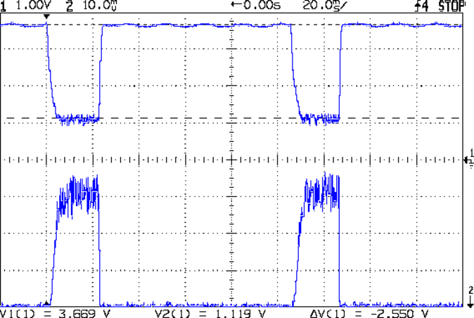
The whole point of the Hall effect current sensor was to get a reasonably efficient linear LED driver that could control the LED current until the battery voltage matched the LED forward drop. Based on the preliminary firmware, it works pretty well.
With a setpoint of 160 mA, the current stabilizes around 150 mA due to the Arduino’s 0.4% PWM resolution. It steps back and forth between 150 and 190 mA as the loop bumps the PWM by one count; these scope shots came from the lower current passes.
At 8.4 V from the bench supply, the MOSFET sees about 2 V. The top trace is the drain voltage, the bottom is LED current at 50 mA/div:
VIN 8.4 V – VD ILED 50 mA-div
At 7.4 V, close to the nominal voltage during most of the discharge curve, the drain sees about 1 V:
VIN 7.4 V – VD ILED 50 mA-div
And at 6.4 V, even though the drain voltage hits zero, the current remains around 150 mA:
VIN 6.4 V – VD ILED 50 mA-div
Admittedly, down there the loop doesn’t have much in the way of control authority, but I planned to turn the lights out at about that point, anyway.
The driver efficiency is 86% at 7.4 V and it’s pretty nearly 100% at 6.4 V.
Of course, the Hall effect circuitry and Arduino Pro Mini soak up another 40 mA or so, so (assuming a 10% duty cycle) the overall efficiency is down around 70%, but that’s including the debugging LEDs and suchlike, so some tweaking is in order.
//-- Read AI channel
//      averages several readings to improve noise performance
//		returns value in volts assuming known VCC ref voltage

#define NUM_T_SAMPLES    10

float ReadAI(byte PinNum) {

  word RawAverage;

  digitalWrite(PIN_SYNC,HIGH);					// scope sync

  RawAverage = (word)analogRead(PinNum);		// prime the averaging pump

  for (int i=2; i <= NUM_T_SAMPLES; i++) {
    RawAverage += (word)analogRead(PinNum);
  }

  digitalWrite(PIN_SYNC,LOW);

  RawAverage /= NUM_T_SAMPLES;

  return Vcc * (float)RawAverage / 1024.0;

}
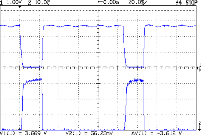
The PIN_SYNC output produces the upper trace, with the LED current in the lower trace at 50 mA/div:
Arduino Analog 10x sample avg – ILED 50 mA-div
In round numbers, ten samples require 1.1 ms and cover about 35 PWM pulses (using 32 kHz PWM, as you really should if you need an actual analog voltage).
Because the samples occur asynchronously with respect to the PWM pulses, the computed average comes out surprisingly close to the actual average. Fewer samples would probably be just as good, but I’m in no hurry.
VG 1193 mV – ID 50 mA-div – 1 ms PWM filter – overview
The top trace is the gate drive at 200 mV/div, the bottom trace is the LED current at 50 mA/div. Expanding the timebase gives a closer look at the fuzz:
VG 1193 mV – ID 50 mA-div – 1 ms PWM filter
Yup, that’s what deriving an analog voltage from a PWM output looks like. Verily, you’re seeing a 32 kHz PWM passed through a 1 ms = 160 Hz low-pass RC filter; the PWM frequency is 2 decades + 1 octave above the filter, so the 5 Vpp digital signal should be down 46 dB. Squinting at the ripple, it’s maybe 40 mV = -42 dB, which is certainly close enough, all things considered.
The MOSFET controlling the LED current operates in its linear region (the whole point of this exercise!) and acts as a Class A amplifier. The datasheet says the forward transconductance is 21 S at VDS = 5 V and ID = 8 A, which certainly isn’t what we have here (about 1 V and 150 mA); you’d expect a 40 mV ripple to produce 840 mA of sawtooth. Under these conditions, the transconductance seems to be 2.5 S = 100 mA/40 mV.
Anyhow, because the gate drive comes from an Arduino PWM output, it has 0.4% resolution and the voltage steps by a bit under 20 mV per PWM increment. Here’s what increasing the PWM output by one count looks like:
VG 1213 mV – ID 50 mA-div – 1 ms PWM filter – overview
Expanding the timebase:
VG 1213 mV – ID 50 mA-div – 1 ms PWM filter
The gate drive is 20 mV higher and the current is 50 mA higher, so the transconductance again works out to 2.5 S.
Note bene: The smallest gate voltage increment produces 50 mA more LED current. It works the same way in the other direction, too, putting a lower limit on the allowable LED current: when the ripple becomes larger than the nominal current, what’s the point?
So, not surprisingly, precise LED current control isn’t possible with an Arduino’s PWM output, at least under these conditions. Using 16 bit PWM would increase the resolution (by a factor of 256), but the PWM ripple means the LED current varies by nearly 2/3 of the setpoint: 100 mApp for a 160 mA nominal LED current.
You could apply a more drastic low-pass filter, but remember that the whole point is to blink the LEDs, not gradually turn them on and off. Eyeballometrically, the LED current risetime = 7 ms, which is very roughly what you’d expect from the 1 ms filter time constant: 5 τ = 99.3%. Doubling the filter time constant wouldn’t be a step in the right direction…
To do this right, you need a real DAC with maybe 10 or 12 bit output (and careful attention to analog layout), which would be absurd in a circuit with an Arduino Pro Mini jammed on top.
Given that it’s just blinking LEDs, none of this really matters: the LEDs are shatteringly bright and blink most satisfactorily. It’s a keeper, even with all that ripple…