This may come in handy for something, like measuring LED output:
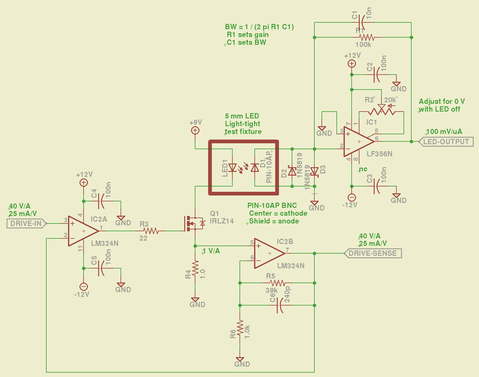
The LM324 converts the input voltage to an LED drive current, scaled by the sense resistor and the gain of IC2B to 25 mA/V. The feedback loop closes through the MOSFET and C6 rolls off the response, so there’s a nasty overshoot on the leading edge of input pulses where the current increases faster than the op amp can tamp it down:

The LM356 acts as a transimpedance amplifer to convert the photodiode current to voltage. The PIN-10AP specs say it should operate in photovoltaic mode with zero bias and that more than -3V of bias will kill the photodiode; the LM356 should hold its inverting input at virtual ground, but the two 1N5819 Schottky diodes enforce that limit. There being zero volts across the diodes, they don’t leak in either direction, so it’s all good.
The circuit is an embarrassing hairball on solderless breadboard, so use your imagination…
You could mash this together with the LED Curve Tracer, although you’d want better low-current resolution from the Arduino output.

Comments
4 responses to “LED Driver + Zero-bias Photodiode Amplifier”
Ed, did you try a bipolar transistor in place of the FET? I’m thinking that would require much less slewing from the first op amp so it might speed things up. Also less capacitive load on that op amp’s output, for that matter. Just a thought…
Nope, that bag of logic-level FETs was just too handy.
There’s surely a power Darlington somewhere in the pile that should suffice; the LM324 doesn’t have a lot of output drive, which is what made the FET attractive in the first place.
That column just went read-only, but I’m sure this will be useful later. Thanks for the nudge…
[…] « LED Driver + Zero-bias Photodiode Amplifier […]
[…] mode directly connected to the oscilloscope, but you’d want to run it through a low-gain transimpedance amplifier to get the zero bias photocurrent and a comparator for a clean digital edge. That’s […]