Ed Nisley's Blog: Shop notes, electronics, firmware, machinery, 3D printing, laser cuttery, and curiosities. Contents: 100% human thinking, 0% AI slop.
Category: Software
General-purpose computers doing something specific
Given Cycliq’s tech support recommendation to never, ever delete files from the camera’s MicroSD card, I’m now copying the files to the 500 GB network drive thusly:
rsync -au --progress /media/ed/Fly6 /mnt/video/
The Fly6 saws off a 400-800 MB file every 10.000 minutes, so a typical ride produces 4 GB of data.
The Sony HDR-AS30V emits a 4.2 GB file every 22:43 minutes: call it 12 GB per ride.
Somewhat to my surprise, both copy operations can proceed concurrently at 4 MB/s apiece. For unknown reasons, the drive doesn’t record the creation times for any data files:
ll /mnt/video/Fly6/DCIM/10450608/
total 4.2G
-rwxr-xr-x 1 ed root 476M 2057-09-06 19:40 14350001.AVI
-rwxr-xr-x 1 ed root 559M 2057-09-06 19:40 14450002.AVI
-rwxr-xr-x 1 ed root 568M 2057-09-06 19:40 14550003.AVI
-rwxr-xr-x 1 ed root 559M 2057-09-06 19:40 15040004.AVI
-rwxr-xr-x 1 ed root 277M 2057-09-06 19:40 15140005.AVI
-rwxr-xr-x 1 ed root 476M 2057-09-06 19:40 15240006.AVI
-rwxr-xr-x 1 ed root 476M 2057-09-06 19:40 15340007.AVI
-rwxr-xr-x 1 ed root 476M 2057-09-06 19:40 15440008.AVI
-rwxr-xr-x 1 ed root 424M 2057-09-06 19:40 15540009.AVI
The directories generally have the right dates, though, so maybe I’ve screwed up an obscure Samba / CIFS settings. The diratime option should be turned on by default.
Armed with bags of electronic parts and boxes of meters, I’ll be helping folks at the CNC Workshop understand the electrical limitations of the Arduino microcontrollers they’re building into projects.
When you download that file, you’ll get something ending in .zip.odt. Rename it to remove the .odt extension, because it’s really a ZIP file; WordPress doesn’t allow users to uploads ZIP files.
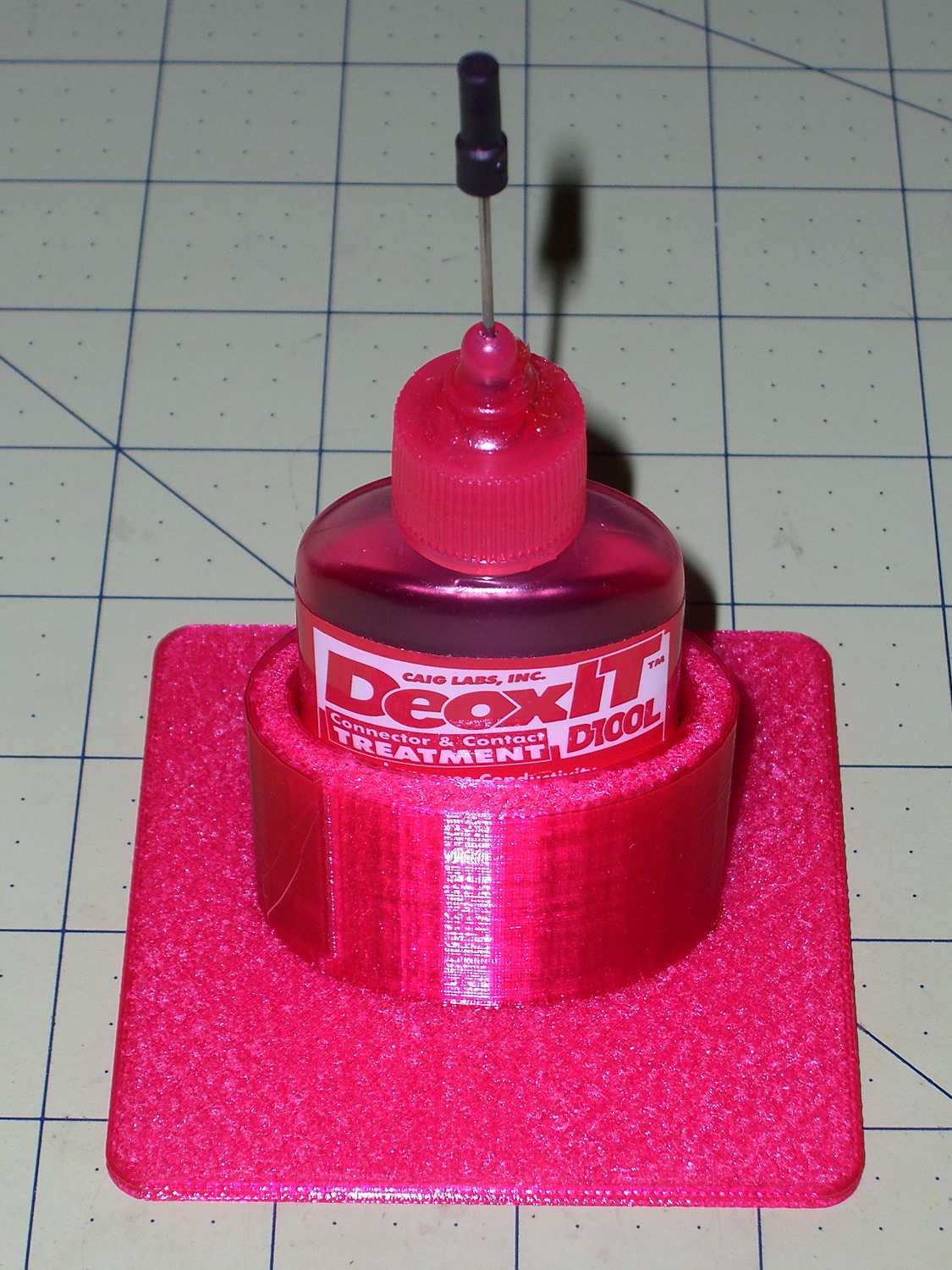
Having found my lifetime supply of DeoxIT slouched against something that didn’t appreciate a thin coating of red oil:
Caig DeoxIT bottle holder
The solid model consists of two squashed cylinders atop a slab:
DeoxIT Bottle Holder
Applying the resize() operator to both cylinders separately, before the difference() operation, maintains a uniform (and grossly overqualified) 5 mm wall thickness, which you wouldn’t get by squashing them after the difference().
The 2.5 mm slab gets nice, rounded corners from a hull() shrinkwrapping a quartet of squat cylinders; Slic3r applies Hilbert Curve infill to the top & bottom surfaces to produce a nice pattern. I admit to being easily pleased.
The OpenSCAD source code took about ten minutes to write and two hours to print:
The parameter order matters: the -ss must come before the -i input file name and the -t must come after it. Otherwise, avconv will copy the entire file before extracting the clip, which can be tedious.
The Fly6 camera produced a video file containing ten minutes of variations on this theme:
Fly6 – 0842001.AVI – Video compression failure
The top of the image looked pretty good, but then the decompression stalls and smears a single, slowly degenerating, line down the rest of the frame. The other files from that trip looked just fine.
As it turned out, extracting a few seconds with avconv or binary-copying the first few megabytes with dd produced playable copies: the original file tripped vlc’s decompression, but the source data was in the file and the copies worked.
Soooo, I could recover the video. Not that it was particularly important, but knowing how might matter some day.
Video is weird.
The Cycliq tech support folks recommend regularly formatting the MicroSD card using the Official SD Association Program (Windows-only, of course), not erasing any video files, and generally letting the camera handle the card. This whole affair seems remarkably fragile.
A sampling of the various Y connectors and manifolds that water Mary’s gardens:
Y valve 1
Y valve 2
Garden hose manifold
Those little handles don’t turn nearly as easily as they should and some require far more finger pressure than Mary can exert. Lubrication being unavailing, the solution is to apply torque through a wrench, rather than fingertips, but fiddling around to match the proper wrench with the valve in hand isn’t acceptable.
The first pass at a Universal Wrench:
Hose Valve Knob – with measurements
The embossed sheet (the back of my Geek Scratch Paper) carried the knob shapes & dimensions from the garden to the desk, where I measured & laid out the wrench:
Hose Connector Knob – Build layout
I filched the knob design from the OXO Can Opener Handle, made it somewhat taller, and applied a scale() operation to mash it into an ellipse aligned with the wrench slot. That huge hexagonal socket in the middle bridged just fine, even though the threads came out as distinct cylinders:
Adding one thread width of clearance around the stem to form the socket produced a slip fit, with a dollop of fast-cure epoxy holding the pieces together.
The wrench fits the largest valve knob with enough clearance to eliminate fiddling. A cylinder punched into the middle of the slot accommodates those teardrop handles:
Hose Connector Knob – Show layout – bottom view
It’s oversized for the smallest “knob”, a vicious triangular stalk that’s murder on the fingers (and not shown here), but fits well enough that, should we deploy any of those, she’ll be ready.
The stem diameter can’t be any larger, because the knobs on Valve 1 don’t allow any clearance. It could be more circular, but I doubt that buys anything. The open ends of the slot won’t let mulch pack into the recesses.
I expect a wrench jaw will eventually snap off as the layers delaminate. In that case I’ll either sink a pair of steel pins into each jaw or, more likely, combine the handle & stem into one object, split the whole affair across the jaws, print the two halves, and glue them together so that the threads run in the proper direction to meet the stress.
Be that as it may, as of right now this is The Best Thing I’ve Ever Built…
The OpenSCAD source code:
// Hose connector knob
// Ed Nisley KE4ZNU - June 2015

Layout = "Build";				// Show Build Knob Stem

//- Extrusion parameters - must match reality!

ThreadThick = 0.25;
ThreadWidth = 0.40;

function IntegerMultiple(Size,Unit) = Unit * ceil(Size / Unit);

Protrusion = 0.1;

HoleWindage = 0.2;

//------
// Dimensions

StemOD = 30.0;					// max OD for valve-to-valve clearance

BossOD = 16.0;					// single-ended handle boss

SlotWidth = 13.0;
SlotHeight = 10.0;

StemInset = 10.0;
StemLength = StemInset + SlotHeight + 25.0;
StemSides = 2*4;

KnobOD1 = 70;						// maximum dia without chamfer
KnobOD2 = 60;						// top dia

KnobSides = 4*4;

DomeHeight = 12;					// dome shape above lobes

KnobHeight = DomeHeight + 2*SlotHeight;

DomeOD = KnobOD2 + (KnobOD1 - KnobOD2)*(DomeHeight/KnobHeight);

DomeArcRad = (pow(KnobHeight,2) + pow(DomeOD,2)/4) / (2*DomeHeight);

//- Adjust hole diameter to make the size come out right

module PolyCyl(Dia,Height,ForceSides=0) {			// based on nophead's polyholes

  Sides = (ForceSides != 0) ? ForceSides : (ceil(Dia) + 2);

  FixDia = Dia / cos(180/Sides);

  cylinder(r=(FixDia + HoleWindage)/2,h=Height,$fn=Sides);
}

//-- Stem for valve handles

module Stem() {

	difference() {
		rotate(0*180/StemSides)
			cylinder(d=StemOD,h=StemLength,$fn=StemSides);
		translate([0,0,SlotHeight/2 - Protrusion/2])
			cube([2*StemOD,SlotWidth,(SlotHeight + Protrusion)],center=true);
		translate([0,0,-Protrusion])
			cylinder(d=BossOD,h=SlotHeight,$fn=2*StemSides);
	}

}

//-- Hand-friendly knob

module KnobCap() {
	difference() {
		scale([1.0,0.75,1.0])
		intersection() {
			translate([0,0,(KnobHeight-DomeArcRad)])
				rotate(180/KnobSides)
					sphere(r=DomeArcRad,$fa=180/KnobSides);
				rotate(180/KnobSides)
					cylinder(r1=KnobOD1/2,r2=KnobOD2/2,h=KnobHeight,$fn=KnobSides);
				rotate(180/KnobSides)
					cylinder(r1=KnobOD2/2,r2=KnobOD1/2,h=KnobHeight,$fn=KnobSides);
		}
		translate([0,0,-Protrusion])
			rotate(0*180/StemSides)
				cylinder(d=(StemOD + 2*ThreadWidth),h=(StemInset + Protrusion),$fn=StemSides);
	}
}

//- Build it

if (Layout == "Knob")
	KnobCap();

if (Layout == "Stem")
	Stem();

if (Layout == "Build") {
	translate([-KnobOD1/2,0,0])
		KnobCap();
	translate([StemOD/2,0,StemLength])
		rotate([180,0,0])
			Stem();
}

if (Layout == "Show") {
	translate([0,0,0])
		Stem();
	translate([0,0,StemLength - StemInset])
		KnobCap();
}
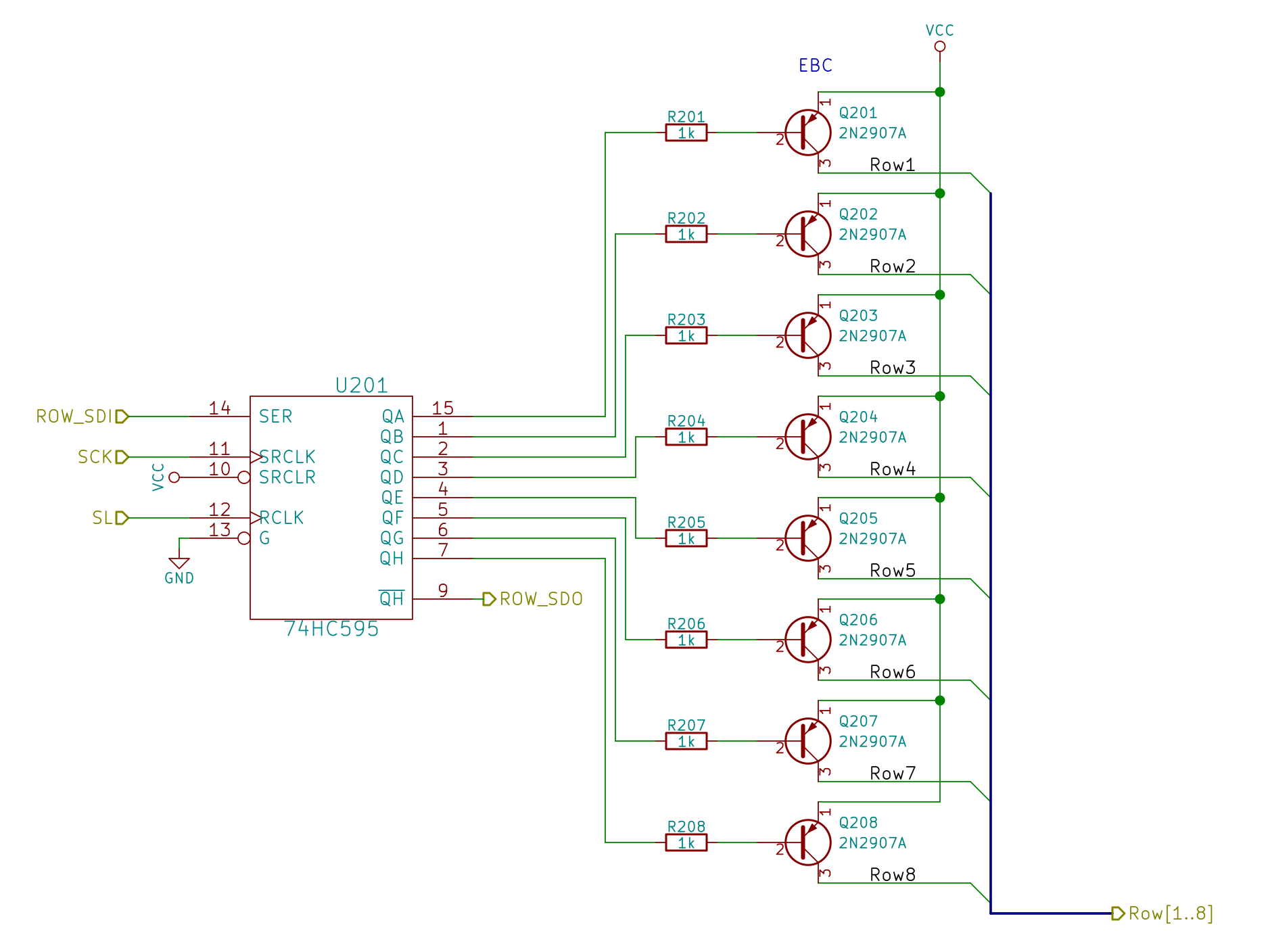
The LED panel requires multiplexing: turning on one of the PNP transistors activates a single row, with the column shift registers determining which of the 24 LEDs in that row will light up. Because each row remains lit until the next one appears, it will be about 1/8 as bright as a “DC” display.
Random LED Dots – Row Drivers
Although the hardware allows turning on more than one row at a time, that’s a Bad Idea that will produce Bad Results: the column shift registers can’t sink that much current.
Bitmapping the whole array requires 8 x 4 = 32 bytes, which isn’t all that much for an ATmega328 with 2 KB of RAM and nothing else on its mind:
I decided to use positive logic in the array, then invert the bits on their way to the SPI hardware.
Setting a single LED to a color value requires chopping the color into its three component RGB bits, clearing the appropriate bits in the array, then stuffing the new ones in place:
The Value comes from a radiation-based random number source that produces 32 bits at a time. I suppose you could just slap 24 of the bits into the column values in a row selected by three other bits to update All! The! Dots! in one shot, but it seemed less exciting to update a single LED on each iteration; the update timing is also an interesting random quantity.
Each iteration of the main() loop squirts the (inverted) bits for a single row through the SPI hardware:
void WaitSPIF(void) {
	while (! (SPSR & (1 << SPIF))) {
//		TogglePin(PIN_HEARTBEAT);
		continue;
	}
}

byte SendRecSPI(byte Dbyte) {			// send one byte, get another in exchange
	SPDR = Dbyte;
	WaitSPIF();
	return SPDR;						// SPIF will be cleared
}

void UpdateLEDs(byte i) {

	SendRecSPI(~LEDs[i].ColB);			// low-active outputs
	SendRecSPI(~LEDs[i].ColG);
	SendRecSPI(~LEDs[i].ColR);
	SendRecSPI(~LEDs[i].Row);

	analogWrite(PIN_DIMMING,LEDS_OFF);	// turn off LED to quench current
	PulsePin(PIN_LATCH);				// make new shift reg contents visible
	analogWrite(PIN_DIMMING,LEDS_ON);

}
I don’t do anything with the returned bytes, but perhaps that’ll be a way to get some random numbers into the program later on.
It turned out that all the green LEDs in a column with one lit LED glowed very, very dimly if they weren’t turned off for a while; a few microseconds while pulsing the shift register parallel load clock seems to work reasonably well. I think the glow comes from microamp-level leakage current through the turned-off PNP transistors, but I haven’t tracked it down yet.
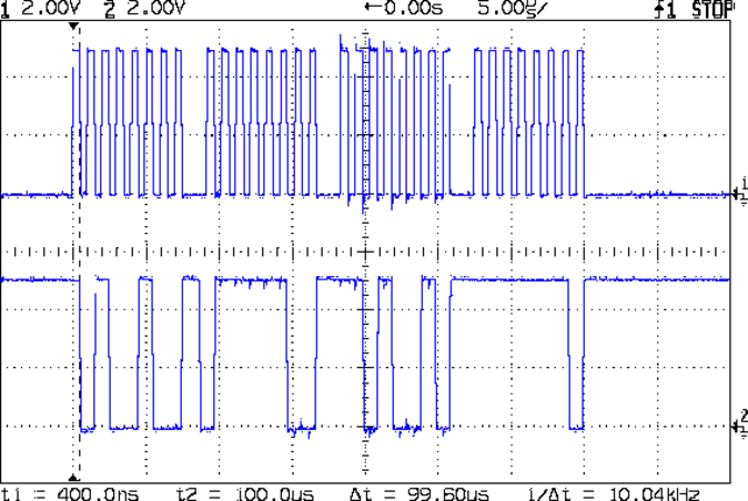
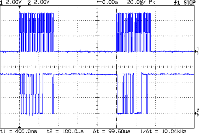
The hardware SPI runs at 1 µs/bit with short gaps while cuing up the next byte:
Hardware SPI – SCLK SDAT
The last byte out (over on the right) contains the row select bits, of which only one can be active (low) at a time.
The main() loop doesn’t have much else to do, so the rows refresh at 10 kHz:
Hardward SPI – Refresh
That means the LEDs in each row are active for only 100 µs and, given a whole-panel refresh of 1250 kHz (!), the LEDs appear to shimmer slightly during eye saccades. It’s a much nicer effect than the flicker produced by slower refresh intervals and has much the same eye-magnet attraction as coherent laser light.
The code emits a scope sync pulse just after Row 7 goes out the door, so you can get ready for the next iteration: