The LED panel requires multiplexing: turning on one of the PNP transistors activates a single row, with the column shift registers determining which of the 24 LEDs in that row will light up. Because each row remains lit until the next one appears, it will be about 1/8 as bright as a “DC” display.
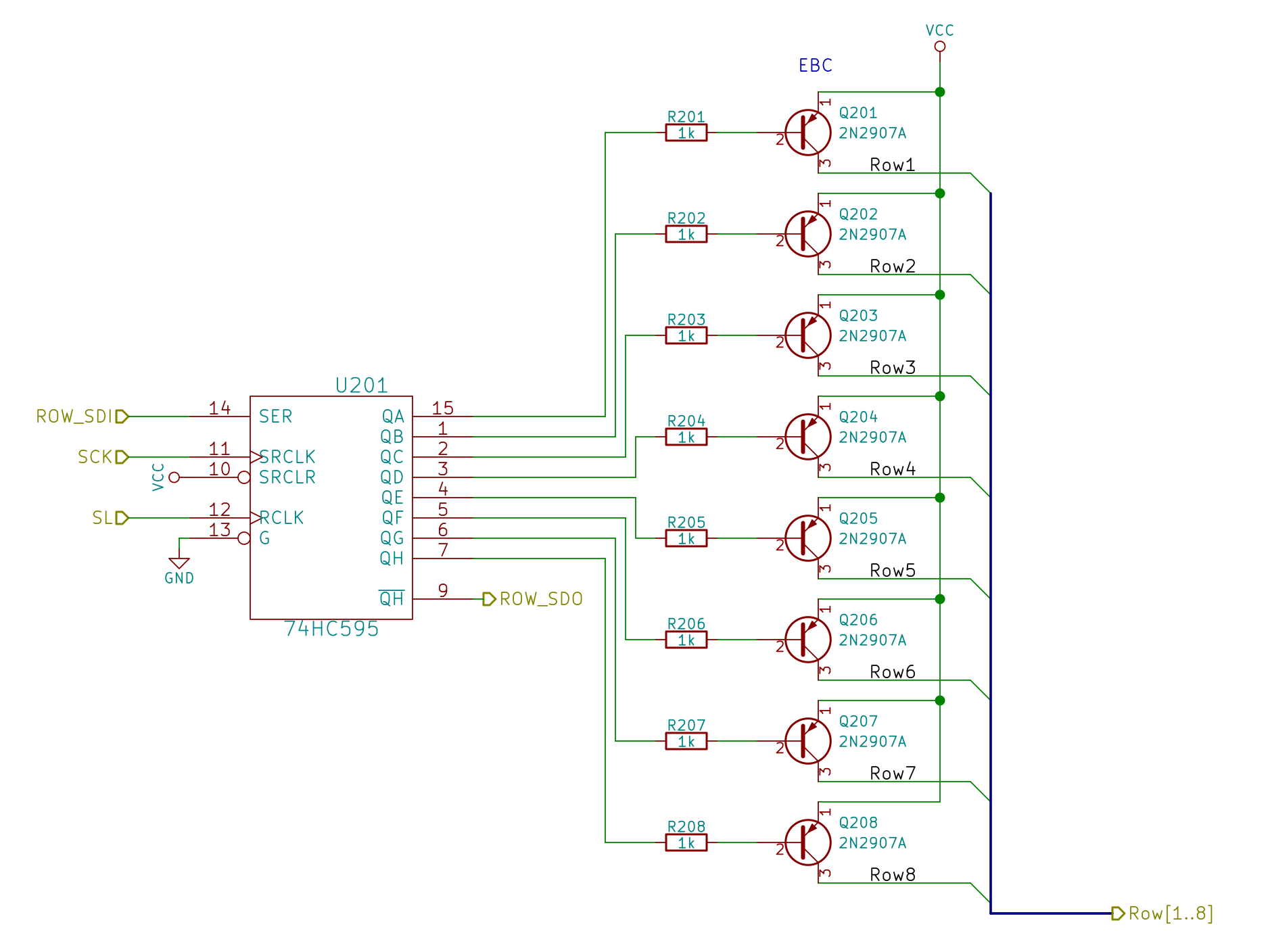
Although the hardware allows turning on more than one row at a time, that’s a Bad Idea that will produce Bad Results: the column shift registers can’t sink that much current.
Bitmapping the whole array requires 8 x 4 = 32 bytes, which isn’t all that much for an ATmega328 with 2 KB of RAM and nothing else on its mind:
typedef struct {
	byte Row;
	byte ColR;
	byte ColG;
	byte ColB;
} LED_BYTES;

#define NUMROWS 8
#define NUMCOLS 8

LED_BYTES LEDs[NUMROWS] = {
	{0x80,0,0,0},
	{0x40,0,0,0},
	{0x20,0,0,0},
	{0x10,0,0,0},
	{0x08,0,0,0},
	{0x04,0,0,0},
	{0x02,0,0,0},
	{0x01,0,0,0},
};
I decided to use positive logic in the array, then invert the bits on their way to the SPI hardware.
Setting a single LED to a color value requires chopping the color into its three component RGB bits, clearing the appropriate bits in the array, then stuffing the new ones in place:
void SetLED(unsigned long Value) {

byte Row,Col,Color,BitMask;

	Row =   (Value >>  8) & 0x07;
	Col =   (Value >> 16) & 0x07;
	Color = (Value >> 24) & 0x07;

	BitMask = (0x80 >> Col);

//	printf("%u %u %u %u\r\n",Row,Col,Color,BitMask);

	LEDs[Row].ColR &= ~BitMask;
	LEDs[Row].ColR |= (Color & 0x04) ? BitMask : 0;

	LEDs[Row].ColG &= ~BitMask;
	LEDs[Row].ColG |= (Color & 0x02) ? BitMask : 0;

	LEDs[Row].ColB &= ~BitMask;
	LEDs[Row].ColB |= (Color & 0x01) ? BitMask : 0;

}
The Value comes from a radiation-based random number source that produces 32 bits at a time. I suppose you could just slap 24 of the bits into the column values in a row selected by three other bits to update All! The! Dots! in one shot, but it seemed less exciting to update a single LED on each iteration; the update timing is also an interesting random quantity.
Each iteration of the main() loop squirts the (inverted) bits for a single row through the SPI hardware:
void WaitSPIF(void) {
	while (! (SPSR & (1 << SPIF))) {
//		TogglePin(PIN_HEARTBEAT);
		continue;
	}
}

byte SendRecSPI(byte Dbyte) {			// send one byte, get another in exchange
	SPDR = Dbyte;
	WaitSPIF();
	return SPDR;						// SPIF will be cleared
}

void UpdateLEDs(byte i) {

	SendRecSPI(~LEDs[i].ColB);			// low-active outputs
	SendRecSPI(~LEDs[i].ColG);
	SendRecSPI(~LEDs[i].ColR);
	SendRecSPI(~LEDs[i].Row);

	analogWrite(PIN_DIMMING,LEDS_OFF);	// turn off LED to quench current
	PulsePin(PIN_LATCH);				// make new shift reg contents visible
	analogWrite(PIN_DIMMING,LEDS_ON);

}
I don’t do anything with the returned bytes, but perhaps that’ll be a way to get some random numbers into the program later on.
It turned out that all the green LEDs in a column with one lit LED glowed very, very dimly if they weren’t turned off for a while; a few microseconds while pulsing the shift register parallel load clock seems to work reasonably well. I think the glow comes from microamp-level leakage current through the turned-off PNP transistors, but I haven’t tracked it down yet.
The hardware SPI runs at 1 µs/bit with short gaps while cuing up the next byte:
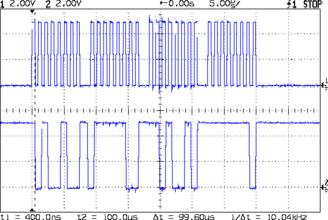
The last byte out (over on the right) contains the row select bits, of which only one can be active (low) at a time.
The main() loop doesn’t have much else to do, so the rows refresh at 10 kHz:
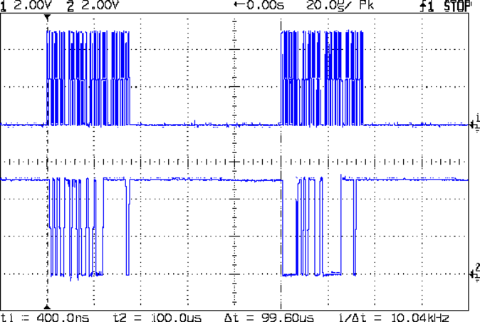
That means the LEDs in each row are active for only 100 µs and, given a whole-panel refresh of 1250 kHz (!), the LEDs appear to shimmer slightly during eye saccades. It’s a much nicer effect than the flicker produced by slower refresh intervals and has much the same eye-magnet attraction as coherent laser light.
The code emits a scope sync pulse just after Row 7 goes out the door, so you can get ready for the next iteration:
	UpdateLEDs(RowIndex);
	if (++RowIndex >= NUMROWS) {
		RowIndex = 0;
		PulsePin(PIN_SYNC);
	}
All in all, it worked right the first time…

Comments
One response to “Random LED Dots: Hardware SPI vs. Data Layout”
[…] third post starts to flesh out the software. [Ed] settled on seven colors (and off) for the display, so the matrix’s total state can be […]