The Smell of Molten Projects in the Morning

Ed Nisley's Blog: Shop notes, electronics, firmware, machinery, 3D printing, laser cuttery, and curiosities. Contents: 100% human thinking, 0% AI slop.

Category: Software

General-purpose computers doing something specific

  • Victoreen 710-104 Ionization Chamber: Shield Support

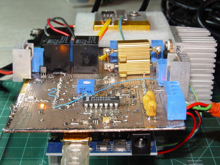
    Although I’d thought of a Mu-metal shield, copper foil tape should be easier and safer to shape into a simple shield. The general idea is to line the interior with copper tape, solder the joints together, cover with Kapton tape to reduce the likelihood of shorts, then stick it in place with some connector pin-and-socket combinations. Putting the tape on the outside would be much easier, but that would surround the circuitry with a layer of plastic that probably carries enough charge to throw things off.

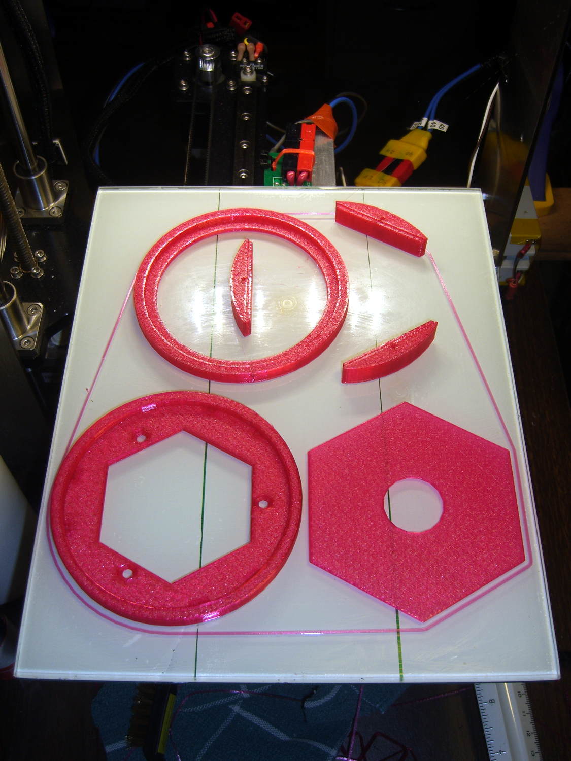
    Anyhow, the hexagonal circuit board model now sports a hexagonal cap to support the shield:

    Victoreen 710-104 Ionization Chamber Fittings - Show with shield
    Victoreen 710-104 Ionization Chamber Fittings – Show with shield

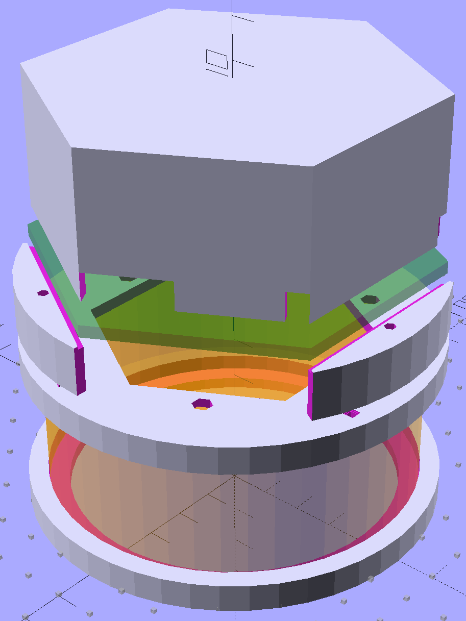
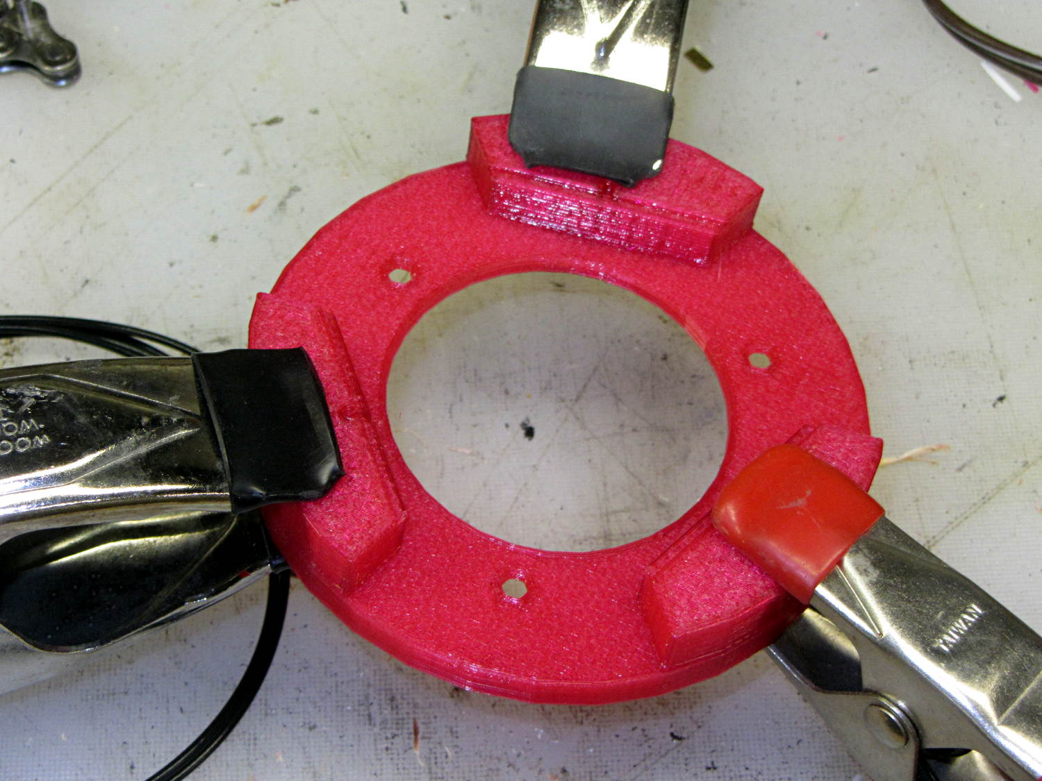
    The ad-hoc openings fit various switches, wires, & twiddlepots:

    Victoreen 710-104 Ionization Chamber Fittings - Shield
    Victoreen 710-104 Ionization Chamber Fittings – Shield

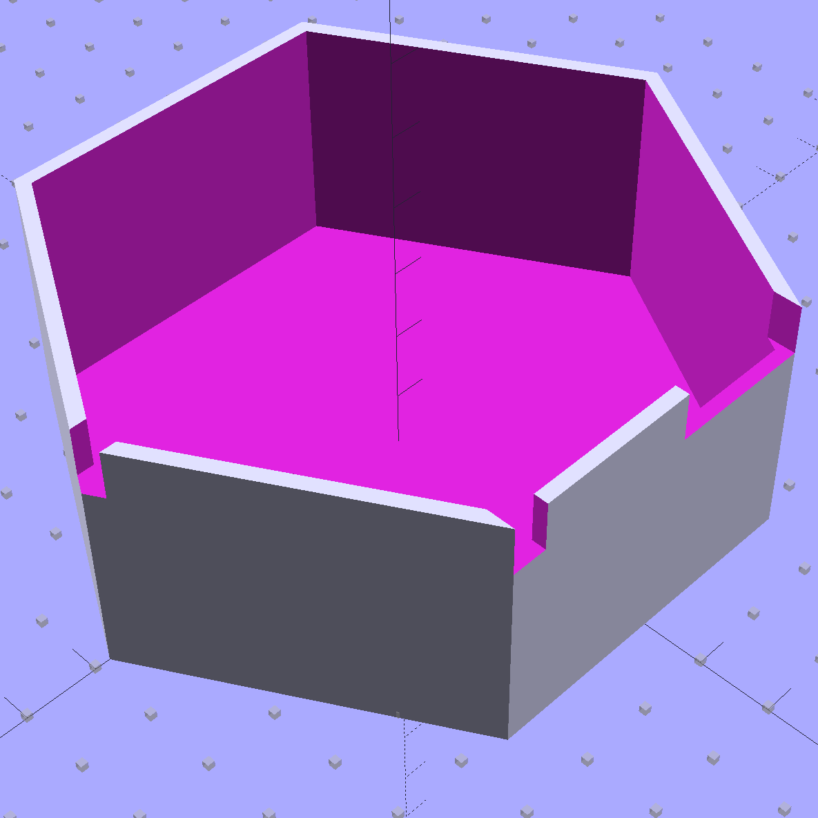
    Ya gotta start somewhere.

    The OpenSCAD source code:

    // Victoreen 710-104 Ionization Chamber Fittings
    // Ed Nisley KE4ZNU July 2015
    
    Layout = "Show";
    					// Show - assembled parts
    					// Build - print can parts + shield
    					// BuildShield - print just the shield
    					// CanCap - PCB insulator for 6-32 mounting studs
    					// CanBase - surrounding foot for ionization chamber
    					// CanLid - generic surround for either end of chamber
    					// PCB - template for cutting PCB sheet
    					// PCBBase - holder for PCB atop CanCap
    					// Shield - electrostatic shield shell
    
    //- Extrusion parameters must match reality!
    //  Print with 2 shells and 3 solid layers
    
    ThreadThick = 0.25;
    ThreadWidth = 0.40;
    
    HoleWindage = 0.2;
    
    Protrusion = 0.1;			// make holes end cleanly
    
    AlignPinOD = 1.75;			// assembly alignment pins = filament dia
    
    inch = 25.4;
    
    function IntegerMultiple(Size,Unit) = Unit * ceil(Size / Unit);
    
    //- Screw sizes
    
    Tap4_40 = 0.089 * inch;
    Clear4_40 = 0.110 * inch;
    Head4_40 = 0.211 * inch;
    Head4_40Thick = 0.065 * inch;
    Nut4_40Dia = 0.228 * inch;
    Nut4_40Thick = 0.086 * inch;
    Washer4_40OD = 0.270 * inch;
    Washer4_40ID = 0.123 * inch;
    
    //----------------------
    // Dimensions
    
    OD = 0;											// name the subscripts
    LENGTH = 1;
    
    Chamber = [91.0 + HoleWindage,38];				// Victoreen ionization chamber dimensions
    
    Stud = [										// stud welded to ionization chamber lid
    	[6.5,IntegerMultiple(0.8,ThreadThick)],		// flat head -- generous clearance
    	[4.0,9.5],									// 6-32 screw -- ditto
    ];
    NumStuds = 3;
    StudSides = 6;									// for hole around stud
    
    BCD = 2.75 * inch;								// mounting stud bolt circle diameter
    
    PlateThick = 3.0;								// layer atop and below chamber ends
    RimHeight = 4.0;								// extending up along chamber perimeter
    WallHeight = RimHeight + PlateThick;
    WallThick = 5.0;								// thick enough to be sturdy & printable
    CapSides = 8*6;									// must be multiple of 4 & 3 to make symmetries work out right
    
    PCBFlatsOD = 85.0;								// hex dia across flats + clearance
    PCBClearance = ThreadWidth;						// clearance on each flat
    PCBThick = 1.1;
    PCBActual = [PCBFlatsOD/cos(30),PCBThick];
    PCBCutter = [(PCBFlatsOD + 2*PCBClearance)/cos(30),PCBThick - ThreadThick];		// OD = tip-to-tip dia with clearance
    
    echo(str("Actual PCB across flats: ",PCBFlatsOD));
    echo(str(" ... tip-to-tip dia: ",PCBActual[OD]));
    echo(str(" ... thickness: ",PCBActual[LENGTH]));
    
    HolderHeight = 11.0 + PCBCutter[LENGTH];		// thick enough for PCB to clear studs
    HolderShelf = 2.0;								// shelf under PCB edge
    PinAngle = 15;									// alignment pin angle on either side of holder screw
    
    echo(str("PCB holder across flats: ",PCBCutter[OD]*cos(30)));
    echo(str(" ... height: ",HolderHeight));
    
    ShieldInset = 1.0;								// shield inset from actual PCB flat
    ShieldWall = 2.0;								// wall thickness
    Shield = [(PCBFlatsOD - 2*ShieldInset)/ cos(30),35.0];		// electrostatic shield shell shape
    
    //----------------------
    // Useful routines
    
    module PolyCyl(Dia,Height,ForceSides=0) {			// based on nophead's polyholes
    
      Sides = (ForceSides != 0) ? ForceSides : (ceil(Dia) + 2);
    
      FixDia = Dia / cos(180/Sides);
    
      cylinder(r=(FixDia + HoleWindage)/2,
               h=Height,
    	   $fn=Sides);
    }
    
    //- Locating pin hole with glue recess
    //  Default length is two pin diameters on each side of the split
    
    module LocatingPin(Dia=AlignPinOD,Len=0.0) {
    
    	PinLen = (Len != 0.0) ? Len : (4*Dia);
    
    	translate([0,0,-ThreadThick])
    		PolyCyl((Dia + 2*ThreadWidth),2*ThreadThick,4);
    
    	translate([0,0,-2*ThreadThick])
    		PolyCyl((Dia + 1*ThreadWidth),4*ThreadThick,4);
    
    	translate([0,0,-Len/2])
    		PolyCyl(Dia,Len,4);
    
    }
    
    module ShowPegGrid(Space = 10.0,Size = 1.0) {
    
      RangeX = floor(100 / Space);
      RangeY = floor(125 / Space);
    
    	for (x=[-RangeX:RangeX])
    	  for (y=[-RangeY:RangeY])
    		translate([x*Space,y*Space,Size/2])
    		  %cube(Size,center=true);
    }
    
    //-----
    
    module CanLid() {
    
    	difference() {
    		cylinder(d=Chamber[OD] + 2*WallThick,h=WallHeight,$fn=CapSides);
    		translate([0,0,PlateThick])
    			PolyCyl(Chamber[OD],Chamber[1],CapSides);
    	}
    
    }
    
    module CanCap() {
    
    	difference() {
    		CanLid();
    
    		translate([0,0,-Protrusion])											// central cutout
    			rotate(180/6)
    				cylinder(d=BCD,h=Chamber[LENGTH],$fn=6);						//  ... reasonable size
    
    		for (i=[0:(NumStuds - 1)])												// stud clearance holes
    			rotate(i*360/NumStuds)
    				translate([BCD/2,0,0])
    					rotate(180/StudSides) {
    						translate([0,0,(PlateThick - (Stud[0][LENGTH] + 2*ThreadThick))])
    							PolyCyl(Stud[0][OD],2*Stud[0][LENGTH],StudSides);
    						translate([0,0,-Protrusion])
    							PolyCyl(Stud[1][OD],2*Stud[1][LENGTH],StudSides);
    					}
    
    		for (i=[0:(NumStuds - 1)], j=[-1,1])									// PCB holder alignment pins
    			rotate(i*360/NumStuds + j*PinAngle + 60)
    				translate([Chamber[OD]/2,0,0])
    					rotate(180/4 - j*PinAngle)
    						LocatingPin(Len=2*PlateThick - 2*ThreadThick);
    	}
    
    }
    
    module CanBase() {
    
    	difference() {
    		CanLid();
    		translate([0,0,-Protrusion])
    			PolyCyl(Chamber[OD] - 2*5.0,Chamber[1],CapSides);
    	}
    }
    
    module PCBTemplate() {
    
    	difference() {
    		cylinder(d=PCBActual[OD],h=max(PCBActual[LENGTH],3.0),$fn=6);		// actual PCB size, overly thick
    		translate([0,0,-Protrusion])
    			cylinder(d=10,h=10*PCBActual[LENGTH],$fn=12);
    	}
    }
    
    module PCBBase() {
    
    	difference() {
    		cylinder(d=Chamber[OD] + 2*WallThick,h=HolderHeight,$fn=CapSides);		// outer rim
    
    		rotate(30) {
    			translate([0,0,-Protrusion])										// central hex
    				cylinder(d=(PCBActual[OD] - HolderShelf/cos(30)),h=2*HolderHeight,$fn=6);
    
    			translate([0,0,HolderHeight - PCBCutter[LENGTH]])					// hex PCB recess
    				cylinder(d=PCBCutter[OD],h=HolderHeight,$fn=6);
    
    			for (i=[0:NumStuds - 1])											// PCB retaining screws
    				rotate(i*120 + 30)
    					translate([(PCBCutter[OD]*cos(30)/2 + Clear4_40/2 + ThreadWidth),0,-Protrusion])
    						rotate(180/6)
    							PolyCyl(Tap4_40,2*HolderHeight,6);
    
    			for (i=[0:(NumStuds - 1)], j=[-1,1])								// PCB holder alignment pins
    				rotate(i*360/NumStuds + j*PinAngle + 30)
    					translate([Chamber[OD]/2,0,0])
    						rotate(180/4 - j*PinAngle)
    							LocatingPin(Len=PlateThick);
    		}
    
    		for (i=[0:NumStuds - 1])												// segment isolation
    			rotate(i*120 - 30)
    				translate([0,0,-Protrusion]) {
    					linear_extrude(height=2*HolderHeight)
    						polygon([[0,0],[Chamber[OD],0],[Chamber[OD]*cos(60),Chamber[OD]*sin(60)]]);
    				}
    	}
    }
    
    //-- Electrostatic shield
    //		the cutouts are completely ad-hoc
    
    module ShieldShell() {
    
    CutHeight = 7.0;
    
    	difference() {
    		cylinder(d=Shield[OD],h=Shield[LENGTH],$fn=6);
    		translate([0,0,-ShieldWall])
    			cylinder(d=(Shield[OD] - 2*ShieldWall/cos(30)),h=Shield[LENGTH],$fn=6);
    
    		translate([Shield[OD]/4 - 20/2,Shield[OD]/2,(CutHeight - Protrusion)/2])
    			rotate(90)
    				cube([Shield[OD],20,CutHeight + Protrusion],center=true);
    
    		translate([-Shield[OD]/4 + 5/2,Shield[OD]/2,(CutHeight - Protrusion)/2])
    			rotate(90)
    				cube([Shield[OD],5,CutHeight + Protrusion],center=true);
    
    		translate([-Shield[OD]/2,0,(CutHeight - Protrusion)/2])
    				cube([Shield[OD],5,CutHeight + Protrusion],center=true);
    
    	}
    
    }
    
    //----------------------
    // Build it
    
    ShowPegGrid();
    
    if (Layout == "CanLid") {
    	CanLid();
    }
    
    if (Layout == "CanCap") {
    	CanCap();
    }
    
    if (Layout == "CanBase") {
    	CanBase();
    }
    
    if (Layout == "PCBBase") {
    	PCBBase();
    }
    
    if (Layout == "PCB") {
    	PCBTemplate();
    }
    
    if (Layout == "Shield") {
    	ShieldShell();
    }
    
    if (Layout == "Show") {
    	CanBase();
    	color("Orange",0.5)
    		translate([0,0,PlateThick + Protrusion])
    			cylinder(d=Chamber[OD],h=Chamber[LENGTH],$fn=CapSides);
    	translate([0,0,(2*PlateThick + Chamber[LENGTH] + 2*Protrusion)])
    		rotate([180,0,0])
    			CanCap();
    	translate([0,0,(2*PlateThick + Chamber[LENGTH] + 5.0)])
    		PCBBase();
    	color("Green",0.5)
    		translate([0,0,(2*PlateThick + Chamber[LENGTH] + 7.0 + HolderHeight)])
    			rotate(30)
    				PCBTemplate();
    	translate([0,0,(2*PlateThick + Chamber[LENGTH] + 15.0 + HolderHeight)])
    		rotate(30)
    			ShieldShell();}
    
    if (Layout == "Build") {
    
    	translate([-0.50*Chamber[OD],-0.60*Chamber[OD],0])
    		CanCap();
    
    	translate([0.55*Chamber[OD],-0.60*Chamber[OD],0])
    		rotate(30)
    			translate([0,0,Shield[LENGTH]])
    				rotate([0,180,0])
    					ShieldShell();
    
    	translate([-0.25*Chamber[OD],0.60*Chamber[OD],0])
    		CanBase();
    	translate([0.25*Chamber[OD],0.60*Chamber[OD],0])
    		PCBBase();
    }
    
    if (Layout == "BuildShield") {
    
    	translate([0,0,Shield[LENGTH]])
    		rotate([0,180,0])
    				ShieldShell();
    
    }
    
  • Victoreen 710-104 Ionization Chamber: Circuit Fixture

    The general idea is to put the electrometer circuitry directly atop the Victoreen 710-104 ionization chamber, so as to minimize the distance from the center collector electrode to the electrometer input. After a few false starts, this looked promising:

    Victoreen 710-104 Ionization Chamber Fittings - Show layout
    Victoreen 710-104 Ionization Chamber Fittings – Show layout

    The hexagonal circuit board fits the can so nicely that I’ll run with it, despite the over-the-top twee factor. Because it’s so hard to freehand a hex, I printed the green object as a tracing template, despite having the Slic3r preview show the parts just barely fitting on the M2 platform:

    Victoreen 710-104 Ionization Chamber Fittings - Build layout
    Victoreen 710-104 Ionization Chamber Fittings – Build layout

    Fortunately, my configuration hand is strong:

    Victoreen 710-104 Fittings - on M2 platform
    Victoreen 710-104 Fittings – on M2 platform

    The skirt measures 0.25±0.05 around the entire perimeter, with a slight positive bias (platform too low) along the left side and a corresponding negative bias on the right. Both sides look just fine to me.

    A pair of alignment pegs hold each board support in place while gluing:

    Victoreen 710-104 Fittings - clamping
    Victoreen 710-104 Fittings – clamping

    Next time around, I’ll glue the supports with the circuit board template laid in place to ensure the edges have the proper orientation, but they came out surprisingly close just by matching the outer perimeters. Of course, I probably bandsawed / belt sanded the carefully traced hex just slightly off-kilter.

    The outer perimeter has 48 sides. Making it a multiple of three means each board support has the same pattern of sides and all will be interchangeable. Making it a multiple of four means each quadrant has the same pattern of sides and the ring looks pleasingly symmetrical. The factor-of-three is most important: you want interchangeable supports. Trust me on this.

    The bottom ring keeps the solder dimple that seals the can base off the desk, but I also stuck a quartet of rubber feet on the can for better traction.

    Here’s what it looks like with the two A23 12 V bias batteries in their holders, affixed to the can with foam tape:

    Victoreen 710-104 Fittings - assembled
    Victoreen 710-104 Fittings – assembled

    The OpenSCAD source code includes a few more tweaks:

    // Victoreen 710-104 Ionization Chamber Fittings
    // Ed Nisley KE4ZNU July 2015
    
    Layout = "Show";
    					// Show - assembled parts
    					// Build - print them out!
    					// CanCap - PCB insulator for 6-32 mounting studs
    					// CanBase - surrounding foot for ionization chamber
    					// CanLid - generic surround for either end of chamber
    					// PCB - template for cutting PCB sheet
    					// PCBBase - holder for PCB atop CanCap
    
    BuildTemplate = false;			// true to build PCB template along with everything else
    
    //- Extrusion parameters must match reality!
    //  Print with 2 shells and 3 solid layers
    
    ThreadThick = 0.25;
    ThreadWidth = 0.40;
    
    HoleWindage = 0.2;
    
    Protrusion = 0.1;			// make holes end cleanly
    
    AlignPinOD = 1.75;			// assembly alignment pins = filament dia
    
    inch = 25.4;
    
    function IntegerMultiple(Size,Unit) = Unit * ceil(Size / Unit);
    
    //- Screw sizes
    
    Tap4_40 = 0.089 * inch;
    Clear4_40 = 0.110 * inch;
    Head4_40 = 0.211 * inch;
    Head4_40Thick = 0.065 * inch;
    Nut4_40Dia = 0.228 * inch;
    Nut4_40Thick = 0.086 * inch;
    Washer4_40OD = 0.270 * inch;
    Washer4_40ID = 0.123 * inch;
    
    
    //----------------------
    // Dimensions
    
    OD = 0;											// name the subscripts
    LENGTH = 1;
    
    Chamber = [91.0 + HoleWindage,38];				// Victoreen ionization chamber dimensions
    
    Stud = [										// stud welded to ionization chamber lid
    	[6.5,IntegerMultiple(0.8,ThreadThick)],		// flat head -- generous clearance
    	[4.0,9.5],									// 6-32 screw -- ditto
    ];
    NumStuds = 3;
    StudSides = 6;									// for hole around stud
    
    BCD = 2.75 * inch;								// mounting stud bolt circle diameter
    
    PlateThick = 3.0;								// layer atop and below chamber ends
    RimHeight = 4.0;								// extending up along chamber perimeter
    WallHeight = RimHeight + PlateThick;
    WallThick = 5.0;								// thick enough to be sturdy & printable
    CapSides = 8*6;									// must be multiple of 4 & 3 to make symmetries work out right
    
    PCBFlatsOD = 85.0 + 2*ThreadWidth;				// hex dia across flats + clearance
    PCBThick = 1.1;
    PCB = [PCBFlatsOD / cos(30),PCBThick - ThreadThick];		// OD = tip-to-tip dia
    
    echo(str("Actual PCB across flats: ",PCBFlatsOD - 2*ThreadWidth));
    echo(str(" ... tip-to-tip dia: ",(PCBFlatsOD - 2*ThreadWidth)/cos(30)));
    echo(str(" ... thickness: ",PCBThick));
    
    HolderHeight = 11.0 + PCB[LENGTH];				// thick enough for PCB to clear studs
    HolderShelf = 2.0;								// shelf under PCB edge
    
    echo(str("PCB holder height: ",HolderHeight));
    echo(str(" ... across flats: ",PCBFlatsOD));
    
    //----------------------
    // Useful routines
    
    module PolyCyl(Dia,Height,ForceSides=0) {			// based on nophead's polyholes
    
      Sides = (ForceSides != 0) ? ForceSides : (ceil(Dia) + 2);
    
      FixDia = Dia / cos(180/Sides);
    
      cylinder(r=(FixDia + HoleWindage)/2,
               h=Height,
    	   $fn=Sides);
    }
    
    //- Locating pin hole with glue recess
    //  Default length is two pin diameters on each side of the split
    
    module LocatingPin(Dia=AlignPinOD,Len=0.0) {
    	
    	PinLen = (Len != 0.0) ? Len : (4*Dia);
    	
    	translate([0,0,-ThreadThick])
    		PolyCyl((Dia + 2*ThreadWidth),2*ThreadThick,4);
    
    	translate([0,0,-2*ThreadThick])
    		PolyCyl((Dia + 1*ThreadWidth),4*ThreadThick,4);
    		
    	translate([0,0,-Len/2])
    		PolyCyl(Dia,Len,4);
    
    }
    
    module ShowPegGrid(Space = 10.0,Size = 1.0) {
    
      RangeX = floor(100 / Space);
      RangeY = floor(125 / Space);
      
    	for (x=[-RangeX:RangeX])
    	  for (y=[-RangeY:RangeY])
    		translate([x*Space,y*Space,Size/2])
    		  %cube(Size,center=true);
    }
    
    //-----
    
    module CanLid() {
    	
    	difference() {
    		cylinder(d=Chamber[OD] + 2*WallThick,h=WallHeight,$fn=CapSides);
    		translate([0,0,PlateThick])
    			PolyCyl(Chamber[OD],Chamber[1],CapSides);
    	}
    	
    }
    
    module CanCap() {
    
    	difference() {
    		CanLid();
    		
    		translate([0,0,-Protrusion])											// central cutout
    //			cylinder(d=(BCD - 2*5.0),h=Chamber[LENGTH],$fn=CapSides);
    			rotate(180/6)
    				cylinder(d=BCD,h=Chamber[LENGTH],$fn=6);
    			
    		for (i=[0:(NumStuds - 1)])												// stud clearance holes
    			rotate(i*360/NumStuds)
    				translate([BCD/2,0,0])
    					rotate(180/StudSides) {
    						translate([0,0,(PlateThick - (Stud[0][LENGTH] + 2*ThreadThick))])
    							PolyCyl(Stud[0][OD],2*Stud[0][LENGTH],StudSides);
    						translate([0,0,-Protrusion])
    							PolyCyl(Stud[1][OD],2*Stud[1][LENGTH],StudSides);
    					}
    					
    		for (i=[0:(NumStuds - 1)], j=[-1,1])									// PCB holder alignment pins
    			rotate(i*360/NumStuds + j*15 + 60)
    				translate([Chamber[OD]/2,0,0])
    					rotate(180/4)
    						LocatingPin(Len=2*PlateThick - 2*ThreadThick);
    	}
    
    }
    
    module CanBase() {
    	
    	difference() {
    		CanLid();
    		translate([0,0,-Protrusion])
    			PolyCyl(Chamber[OD] - 2*5.0,Chamber[1],CapSides);
    	}
    }
    
    module PCBTemplate() {
    	
    	difference() {
    		cylinder(d=((PCBFlatsOD - 2*ThreadWidth)/cos(30)),h=max(PCB[LENGTH],3.0),$fn=6);		// actual PCB size, overly thick
    		translate([0,0,-Protrusion])
    			cylinder(d=10,h=10*PCB[LENGTH],$fn=12);
    	}
    }
    
    module PCBBase() {
    
    	difference() {
    		cylinder(d=Chamber[OD] + 2*WallThick,h=HolderHeight,$fn=CapSides);
    		
    		rotate(30) {
    			translate([0,0,-Protrusion])										// central hex
    				cylinder(d=(PCBFlatsOD - 2*HolderShelf)/cos(30),h=2*HolderHeight,$fn=6);	
    				
    			translate([0,0,HolderHeight - PCB[LENGTH]])							// hex PCB recess
    				cylinder(d=PCB[OD],h=HolderHeight,$fn=6);
    				
    			for (i=[0:NumStuds - 1])											// PCB retaining screws
    				rotate(i*120 + 30)
    					translate([(PCBFlatsOD/2 + Clear4_40/2 + ThreadWidth),0,-Protrusion])
    						rotate(180/6)
    							PolyCyl(Tap4_40,2*HolderHeight,6);
    							
    			for (i=[0:(NumStuds - 1)], j=[-1,1])								// PCB holder alignment pins
    				rotate(i*360/NumStuds + j*15 + 30)
    					translate([Chamber[OD]/2,0,0])
    						rotate(180/4)
    							LocatingPin(Len=PlateThick);
    		}
    		
    		for (i=[0:NumStuds - 1])												// segment isolation
    			rotate(i*120 - 30)
    				translate([0,0,-Protrusion]) {
    					linear_extrude(height=2*HolderHeight)
    						polygon([[0,0],[Chamber[OD],0],[Chamber[OD]*cos(60),Chamber[OD]*sin(60)]]);
    				}
    	}
    	
    
    }
    
    
    //----------------------
    // Build it
    
    ShowPegGrid();
    
    if (Layout == "CanLid") {
    	CanLid();
    }
    
    if (Layout == "CanCap") {
    	CanCap();
    }
    
    if (Layout == "CanBase") {
    	CanBase();
    }
    
    if (Layout == "PCBBase") {
    	PCBBase();
    }
    
    if (Layout == "PCB") {
    	PCBTemplate();
    }
    
    if (Layout == "Show") {
    	CanBase();
    	color("Orange",0.5)
    		translate([0,0,PlateThick + Protrusion])
    			cylinder(d=Chamber[OD],h=Chamber[LENGTH],$fn=CapSides);
    	translate([0,0,(2*PlateThick + Chamber[LENGTH] + 2*Protrusion)])
    		rotate([180,0,0])
    			CanCap();
    	translate([0,0,(2*PlateThick + Chamber[LENGTH] + 5.0)])
    		PCBBase();
    	color("Green",0.5)
    		translate([0,0,(2*PlateThick + Chamber[LENGTH] + 7.0 + HolderHeight)])
    			rotate(30)
    				PCBTemplate();
    }
    
    if (Layout == "Build") {
    	
    	if (BuildTemplate) {
    		translate([-0.50*Chamber[OD],-0.60*Chamber[OD],0])
    			CanCap();
    			
    		translate([0.55*Chamber[OD],-0.60*Chamber[OD],0])
    			rotate(30)
    				PCBTemplate();
    	}
    	else {
    		translate([-0.25*Chamber[OD],-0.60*Chamber[OD],0])
    			CanCap();
    	}
    		
    	translate([-0.25*Chamber[OD],0.60*Chamber[OD],0])
    		CanBase();
    	translate([0.25*Chamber[OD],0.60*Chamber[OD],0])
    		PCBBase();
    }
    
  • Cycliq Fly6 Camera: Copying the Most Recent Files

    Given Cycliq’s tech support recommendation to never, ever delete files from the camera’s MicroSD card, I’m now copying the files to the 500 GB network drive thusly:

    rsync -au --progress /media/ed/Fly6 /mnt/video/
    

    The Fly6 saws off a 400-800 MB file every 10.000 minutes, so a typical ride produces 4 GB of data.

    The Sony HDR-AS30V emits a 4.2 GB file every 22:43 minutes: call it 12 GB per ride.

    Somewhat to my surprise, both copy operations can proceed concurrently at 4 MB/s apiece. For unknown reasons, the drive doesn’t record the creation times for any data files:

    ll /mnt/video/Fly6/DCIM/10450608/
    total 4.2G
    -rwxr-xr-x 1 ed root 476M 2057-09-06 19:40 14350001.AVI
    -rwxr-xr-x 1 ed root 559M 2057-09-06 19:40 14450002.AVI
    -rwxr-xr-x 1 ed root 568M 2057-09-06 19:40 14550003.AVI
    -rwxr-xr-x 1 ed root 559M 2057-09-06 19:40 15040004.AVI
    -rwxr-xr-x 1 ed root 277M 2057-09-06 19:40 15140005.AVI
    -rwxr-xr-x 1 ed root 476M 2057-09-06 19:40 15240006.AVI
    -rwxr-xr-x 1 ed root 476M 2057-09-06 19:40 15340007.AVI
    -rwxr-xr-x 1 ed root 476M 2057-09-06 19:40 15440008.AVI
    -rwxr-xr-x 1 ed root 424M 2057-09-06 19:40 15540009.AVI
    

    The directories generally have the right dates, though, so maybe I’ve screwed up an obscure Samba / CIFS settings. The diratime option should be turned on by default.

  • CNC Workshop 2015: Arduino Survival Guide, Workshop Edition

    MOSFET RDS Tester - Arduino
    MOSFET RDS Tester – Arduino

    Armed with bags of electronic parts and boxes of meters, I’ll be helping folks at the CNC Workshop understand the electrical limitations of the Arduino microcontrollers they’re building into projects.

    The presentation in PDF form:

    Arduino Survival Guide – Workshop Edition – CNC Workshop 2015

    We’ll wing it with the source code, because nothing’s more than a few lines long…

  • CNC Workshop 2015: Practical Solid Modeling with OpenSCAD

    HP Plotter Pen Polygon
    HP Plotter Pen Polygon

    This afternoon at the CNC Workshop, I’ll be bootstrapping folks into creating 3D-printable solid models with Openscad.

    The presentation in PDF form:

    Practical Solid Modeling for 3D Printing with OpenSCAD – CNC Workshop 2015

    The OpenSCAD source code for the exercises, in case you don’t want to type along:

    Practical Solid Modeling for 3D Printing with OpenSCAD – Models.zip.odt

    When you download that file, you’ll get something ending in .zip.odt. Rename it to remove the .odt extension, because it’s really a ZIP file; WordPress doesn’t allow users to uploads ZIP files.

  • Caig DeoxIT Bottle Holder

    Having found my lifetime supply of DeoxIT slouched against something that didn’t appreciate a thin coating of red oil:

    Caig DeoxIT bottle holder
    Caig DeoxIT bottle holder

    The solid model consists of two squashed cylinders atop a slab:

    DeoxIT Bottle Holder
    DeoxIT Bottle Holder

    Applying the resize() operator to both cylinders separately, before the difference() operation, maintains a uniform (and grossly overqualified) 5 mm wall thickness, which you wouldn’t get by squashing them after the difference().

    The 2.5 mm slab gets nice, rounded corners from a hull() shrinkwrapping a quartet of squat cylinders; Slic3r applies Hilbert Curve infill to the top & bottom surfaces to produce a nice pattern. I admit to being easily pleased.

    The OpenSCAD source code took about ten minutes to write and two hours to print:

    // CAIG DeoxIT Bottle Holder
    // Ed Nisley KE4ZNU - June 2015
    
    //- Extrusion parameters - must match reality!
    
    ThreadThick = 0.25;
    ThreadWidth = 0.40;
    
    function IntegerMultiple(Size,Unit) = Unit * ceil(Size / Unit);
    
    Protrusion = 0.1;
    
    HoleWindage = 0.2;
    
    //------
    // Dimensions
    
    BottleOD = [40,21,30];			// actual dia, holder depth
    
    Clearance = [1.0,1.0,0.0];				// around bottle
    
    WallThick = 5.0;
    
    PlateThick = IntegerMultiple(2.5,ThreadThick);
    PlateRound = 5.0;
    
    NumSides = 8*4;
    
    //- Build it
    
    union() {
    	hull() {
    		for (i=[-1,1], j=[-1,1]) {
    			translate([i*(BottleOD[0] - PlateRound),j*(BottleOD[0] - PlateRound),0])
    				cylinder(r=PlateRound,h=PlateThick,$fn=NumSides);
    		}
    	}
    	difference() {
    		resize(BottleOD + 2*Clearance + [2*WallThick,2*WallThick,WallThick])
    			cylinder(d=BottleOD[0],h=1,$fn=NumSides);
    		translate([0,0,WallThick])
    			resize(BottleOD + 2*Clearance + [0,0,WallThick])
    				cylinder(d=BottleOD,h=1,$fn=NumSides);
    	}
    }
    

    I loves me my 3D printer…

  • Extract-copying A Video Clip

    The magic incantation to extract a few seconds of video from a longer clip and set the output file to use the same codecs:

    avconv -ss 00:00:01 -i /mnt/video/2015-05-30/08420001.AVI -codec copy -t 5 08420001-clip.avi
    

    The parameter order matters: the -ss must come before the -i input file name and the -t must come after it. Otherwise, avconv will copy the entire file before extracting the clip, which can be tedious.

    The Fly6 camera produced a video file containing ten minutes of variations on this theme:

    Fly6 - 0842001.AVI - Video compression failure
    Fly6 – 0842001.AVI – Video compression failure

    The top of the image looked pretty good, but then the decompression stalls and smears a single, slowly degenerating, line down the rest of the frame. The other files from that trip looked just fine.

    As it turned out, extracting a few seconds with avconv or binary-copying the first few megabytes with dd produced playable copies: the original file tripped vlc’s decompression, but the source data was in the file and the copies worked.

    Soooo, I could recover the video. Not that it was particularly important, but knowing how might matter some day.

    Video is weird.

    The Cycliq tech support folks recommend regularly formatting the MicroSD card using the Official SD Association Program (Windows-only, of course), not erasing any video files, and generally letting the camera handle the card. This whole affair seems remarkably fragile.