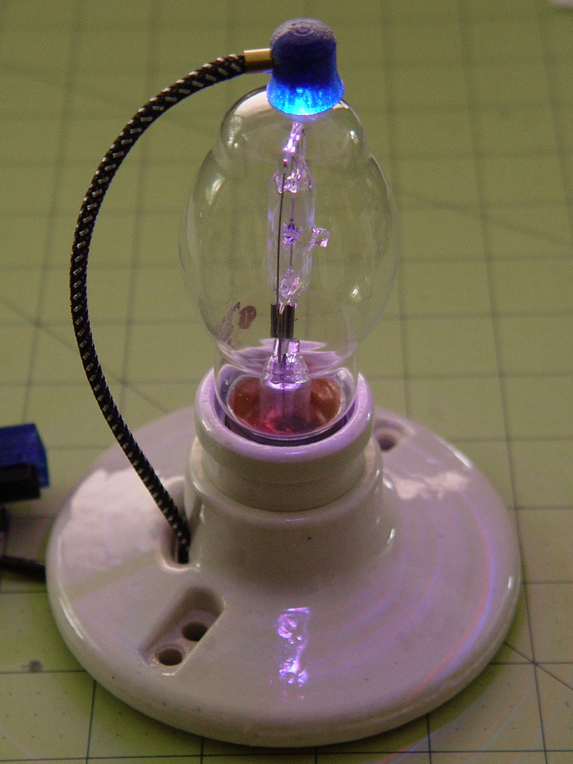
A test lashup to see how it all works, with an ersatz plate cap atop the IBM 21HB5A Beam Power tube on the far right end:
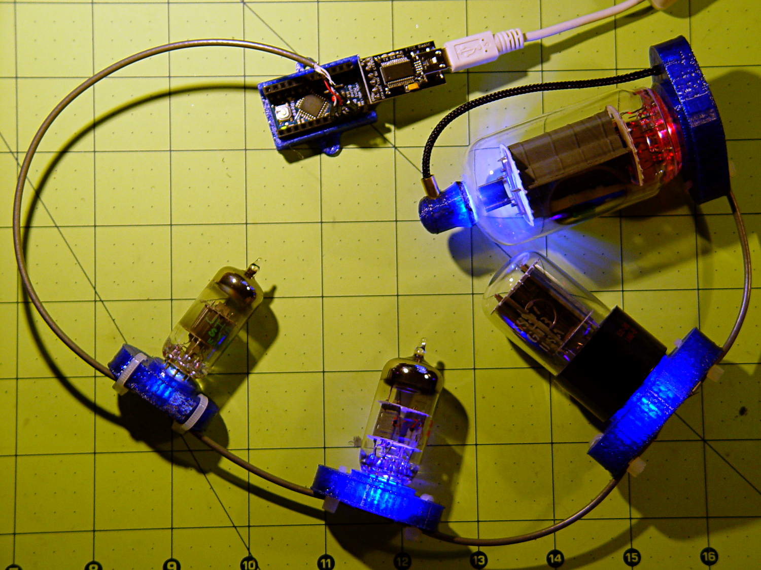
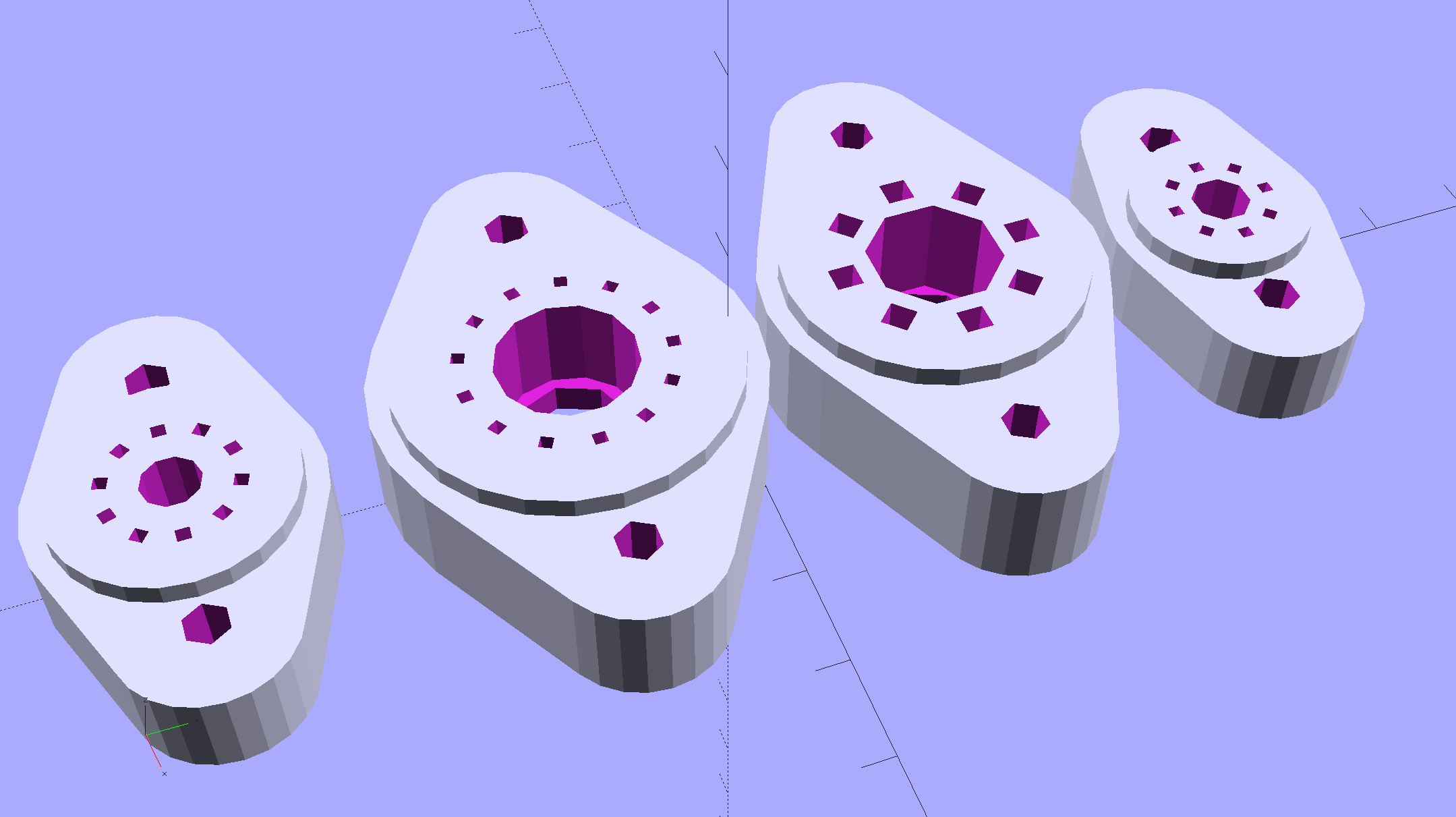
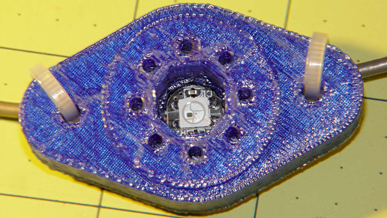
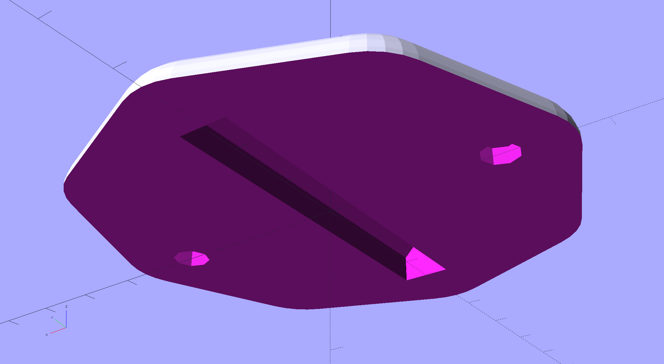
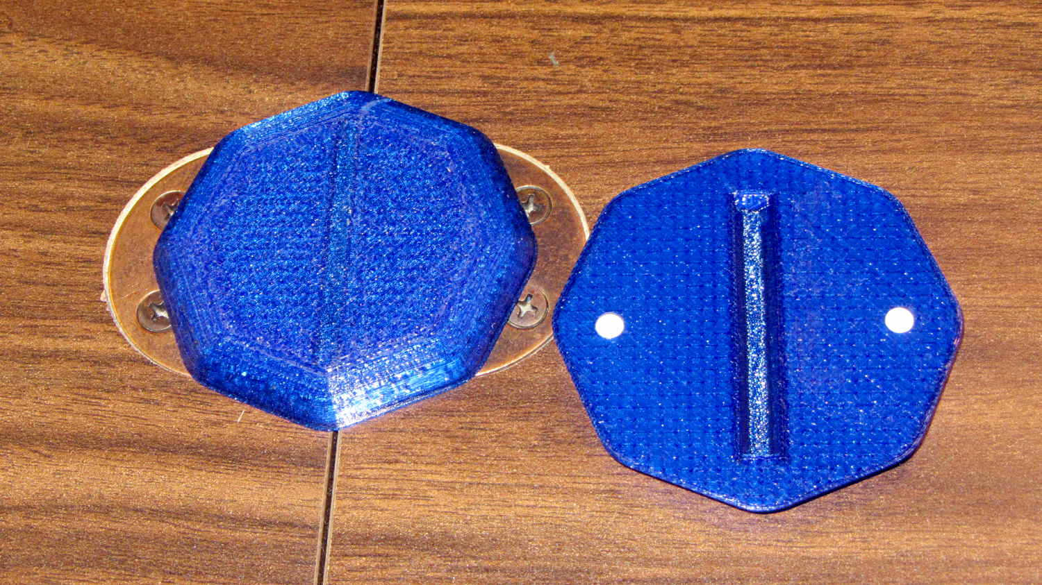
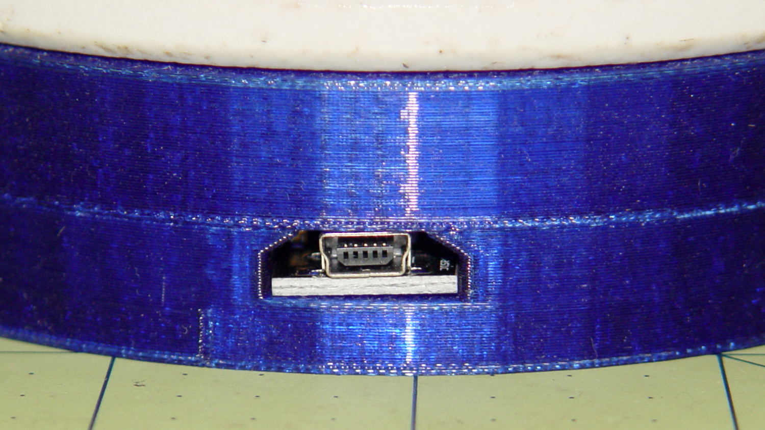
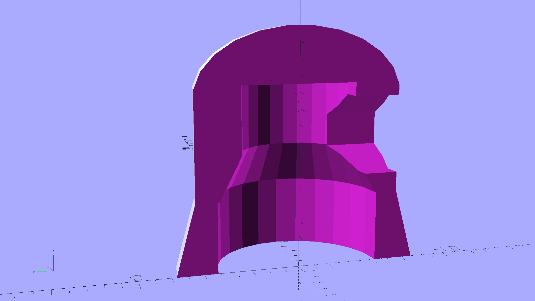
Those sockets must mount in a chassis, not flop around loose on the cable.
I hacked the code out of the Hard Drive Platter Mood Light; there’s a lot to not like about what’s left and I must rethink the overall structure. The colors now run an order of magnitude faster than the Platter Mood Light, with a 90° phase angle between successive Neopixels.
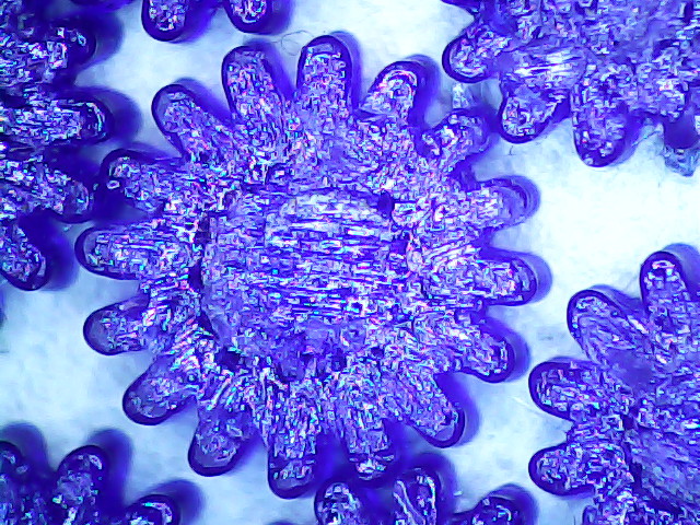
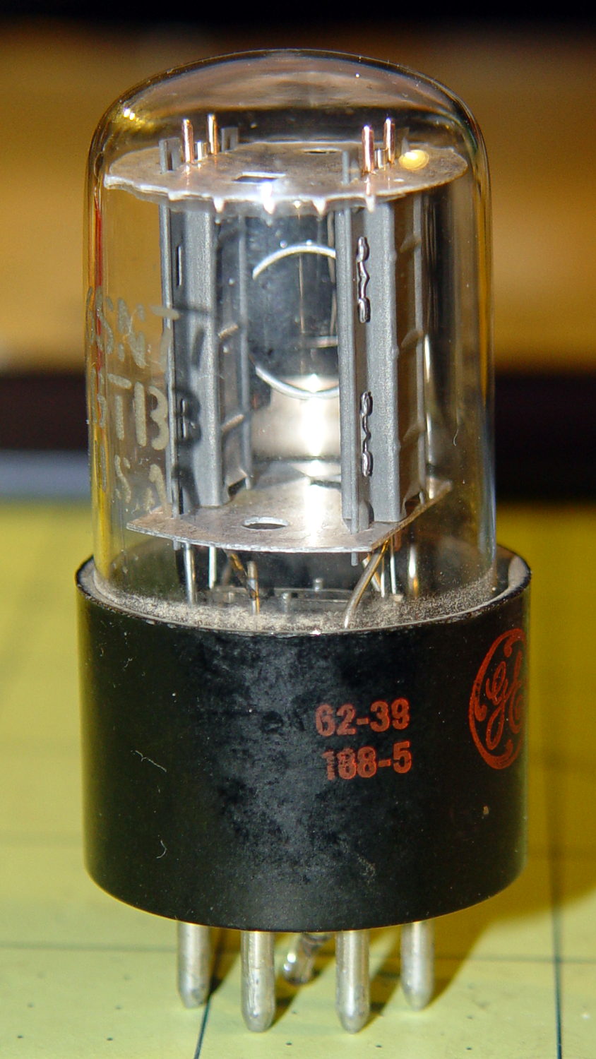
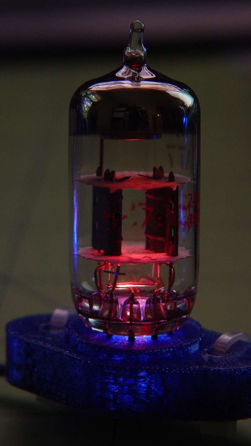
The mica spacers in the 12AT7 Dual Triode tube (second in the sequence, Noval socket) look cool & crystalline:

When the red phase comes around, it becomes a firebottle:
With a touch of fire in its hole, the IBM 21HB5A Beam Power tube looks just flat-out gorgeous, despite that translucent blue plate cap:

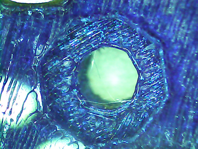
Cool green works pretty well:
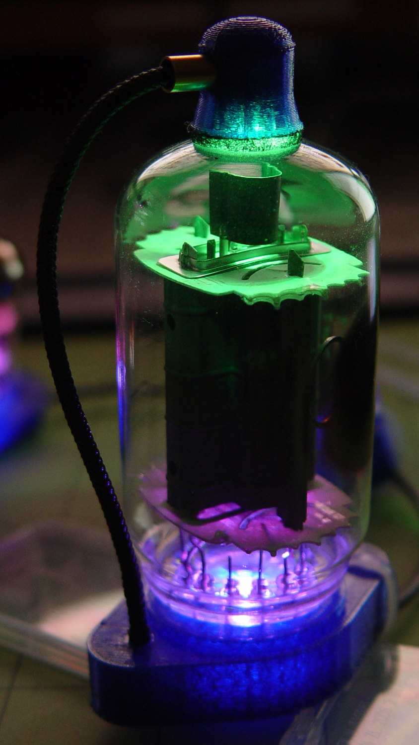
If you wait long enough, it’ll probably turn True IBM Blue.
This worked out even better than I expected!
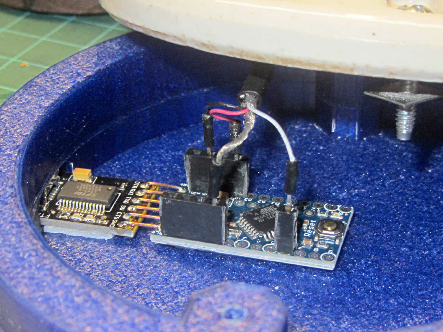
The Arduino source code as a GitHub gist:
| // Neopixel lighting for multiple vacuum tubes | |
| // Ed Nisley – KE4ANU – January 2015 | |
| #include <Adafruit_NeoPixel.h> | |
| //———- | |
| // Pin assignments | |
| const byte PIN_NEO = A3; // DO – data out to first Neopixel | |
| const byte PIN_HEARTBEAT = 13; // DO – Arduino LED | |
| //———- | |
| // Constants | |
| #define UPDATEINTERVAL 25ul | |
| const unsigned long UpdateMS = UPDATEINTERVAL – 1ul; // update LEDs only this many ms apart minus loop() overhead | |
| // number of steps per cycle, before applying prime factors | |
| #define RESOLUTION 100 | |
| // phase difference between tubes for slowest color | |
| #define BASEPHASE (PI/4.0) | |
| // number of LED strips around each tube | |
| #define LEDSTRIPCOUNT 1 | |
| // number of LEDs per strip | |
| #define LEDSTRINGCOUNT 5 | |
| // want to randomize the startup a little? | |
| #define RANDOMIZE true | |
| //———- | |
| // Globals | |
| // instantiate the Neopixel buffer array | |
| Adafruit_NeoPixel strip = Adafruit_NeoPixel(LEDSTRIPCOUNT * LEDSTRINGCOUNT, PIN_NEO, NEO_GRB + NEO_KHZ800); | |
| uint32_t FullWhite = strip.Color(255,255,255); | |
| uint32_t FullOff = strip.Color(0,0,0); | |
| struct pixcolor_t { | |
| byte Prime; | |
| unsigned int NumSteps; | |
| unsigned int Step; | |
| float StepSize; | |
| float TubePhase; | |
| byte MaxPWM; | |
| }; | |
| // colors in each LED | |
| enum pixcolors {RED, GREEN, BLUE, PIXELSIZE}; | |
| struct pixcolor_t Pixels[PIXELSIZE]; // all the data for each pixel color intensity | |
| byte Map[LEDSTRINGCOUNT][LEDSTRIPCOUNT] = {{0},{1},{2},{3},{4}}; // pixel IDs around each tube, bottom to top. | |
| unsigned long MillisNow; | |
| unsigned long MillisThen; | |
| //– Figure PWM based on current state | |
| byte StepColor(byte Color, float Phi) { | |
| byte Value; | |
| Value = (Pixels[Color].MaxPWM / 2.0) * (1.0 + sin(Pixels[Color].Step * Pixels[Color].StepSize + Phi)); | |
| // Value = (Value) ? Value : Pixels[Color].MaxPWM; // flash at dimmest points | |
| // printf("C: %d Phi: %d Value: %d\r\n",Color,(int)(Phi*180.0/PI),Value); | |
| return Value; | |
| } | |
| //– Helper routine for printf() | |
| int s_putc(char c, FILE *t) { | |
| Serial.write(c); | |
| } | |
| //—————— | |
| // Set the mood | |
| void setup() { | |
| pinMode(PIN_HEARTBEAT,OUTPUT); | |
| digitalWrite(PIN_HEARTBEAT,LOW); // show we arrived | |
| Serial.begin(57600); | |
| fdevopen(&s_putc,0); // set up serial output for printf() | |
| printf("Multiple Vacuum Tube Mood Light with Neopixels\r\nEd Nisley – KE4ZNU – January 2016\r\n"); | |
| /// set up Neopixels | |
| strip.begin(); | |
| strip.show(); | |
| // lamp test: run a brilliant white dot along the length of the strip | |
| printf("Lamp test: walking white\r\n"); | |
| strip.setPixelColor(0,FullWhite); | |
| strip.show(); | |
| delay(500); | |
| for (int i=1; i<strip.numPixels(); i++) { | |
| digitalWrite(PIN_HEARTBEAT,HIGH); | |
| strip.setPixelColor(i-1,FullOff); | |
| strip.setPixelColor(i,FullWhite); | |
| strip.show(); | |
| digitalWrite(PIN_HEARTBEAT,LOW); | |
| delay(500); | |
| } | |
| strip.setPixelColor(strip.numPixels() – 1,FullOff); | |
| strip.show(); | |
| delay(500); | |
| // fill the layers | |
| printf(" … fill using Map array\r\n"); | |
| for (int i=0; i < LEDSTRINGCOUNT; i++) { // for each layer | |
| digitalWrite(PIN_HEARTBEAT,HIGH); | |
| for (int j=0; j < LEDSTRIPCOUNT; j++) { // spread color around the layer | |
| strip.setPixelColor(Map[i][j],FullWhite); | |
| strip.show(); | |
| delay(250); | |
| } | |
| digitalWrite(PIN_HEARTBEAT,LOW); | |
| } | |
| // clear to black | |
| printf(" … clear\r\n"); | |
| for (int i=0; i < LEDSTRINGCOUNT; i++) { // for each layer | |
| digitalWrite(PIN_HEARTBEAT,HIGH); | |
| for (int j=0; j < LEDSTRIPCOUNT; j++) { // spread color around the layer | |
| strip.setPixelColor(Map[i][j],FullOff); | |
| strip.show(); | |
| delay(250); | |
| } | |
| digitalWrite(PIN_HEARTBEAT,LOW); | |
| } | |
| delay(1000); | |
| // set up the color generators | |
| MillisNow = MillisThen = millis(); | |
| if (RANDOMIZE) | |
| randomSeed(MillisNow + analogRead(7)); | |
| else | |
| printf("Start not randomized\r\n"); | |
| printf("First random number: %ld\r\n",random(10)); | |
| Pixels[RED].Prime = 7; | |
| Pixels[GREEN].Prime = 5; | |
| Pixels[BLUE].Prime = 3; | |
| printf("Primes: (%d,%d,%d)\r\n",Pixels[RED].Prime,Pixels[GREEN].Prime,Pixels[BLUE].Prime); | |
| unsigned int TubeSteps = (unsigned int) ((BASEPHASE / TWO_PI) * | |
| RESOLUTION * (unsigned int) max(max(Pixels[RED].Prime,Pixels[GREEN].Prime),Pixels[BLUE].Prime)); | |
| printf("Tube phase offset: %d deg = %d steps\r\n",(int)(BASEPHASE*(360.0/TWO_PI)),TubeSteps); | |
| Pixels[RED].MaxPWM = 255; | |
| Pixels[GREEN].MaxPWM = 128; | |
| Pixels[BLUE].MaxPWM = 255; | |
| for (byte c=0; c < PIXELSIZE; c++) { | |
| Pixels[c].NumSteps = RESOLUTION * (unsigned int) Pixels[c].Prime; | |
| Pixels[c].Step = (RANDOMIZE) ? random(Pixels[c].NumSteps) : (3*Pixels[c].NumSteps)/4; | |
| Pixels[c].StepSize = TWO_PI / Pixels[c].NumSteps; // in radians per step | |
| Pixels[c].TubePhase = TubeSteps * Pixels[c].StepSize; // radians per tube | |
| printf("c: %d Steps: %d Init: %d",c,Pixels[c].NumSteps,Pixels[c].Step); | |
| printf(" PWM: %d Phi %d deg\r\n",Pixels[c].MaxPWM,(int)(Pixels[c].TubePhase*(360.0/TWO_PI))); | |
| } | |
| } | |
| //—————— | |
| // Run the mood | |
| void loop() { | |
| MillisNow = millis(); | |
| if ((MillisNow – MillisThen) > UpdateMS) { | |
| digitalWrite(PIN_HEARTBEAT,HIGH); | |
| for (byte c=0; c < PIXELSIZE; c++) { // step to next increment in each color | |
| if (++Pixels[c].Step >= Pixels[c].NumSteps) { | |
| Pixels[c].Step = 0; | |
| printf("Cycle %d steps %d at %8ld delta %ld ms\r\n",c,Pixels[c].NumSteps,MillisNow,(MillisNow – MillisThen)); | |
| } | |
| } | |
| for (int i=0; i < LEDSTRINGCOUNT; i++) { // for each layer | |
| byte Value[PIXELSIZE]; | |
| for (byte c=0; c < PIXELSIZE; c++) { // … for each color | |
| Value[c] = StepColor(c,-i*Pixels[c].TubePhase); // figure new PWM value | |
| // Value[c] = (c == RED && Value[c] == 0) ? Pixels[c].MaxPWM : Value[c]; // flash highlight for tracking | |
| } | |
| uint32_t UniColor = strip.Color(Value[RED],Value[GREEN],Value[BLUE]); | |
| if (false && (i == 0)) | |
| printf("L: %d C: %08lx\r\n",i,UniColor); | |
| for (int j=0; j < LEDSTRIPCOUNT; j++) { // fill layer with color | |
| strip.setPixelColor(Map[i][j],UniColor); | |
| } | |
| } | |
| strip.show(); | |
| MillisThen = MillisNow; | |
| digitalWrite(PIN_HEARTBEAT,LOW); | |
| } | |
| } |