Lighting up that old voltage regulator tube conclusively demonstrated there’s no point in conjuring high voltages in this day & age. Nay, verily, merely lighting the filament of some tubes would require more power than seems reasonable.
A 1B3GT high-voltage regulator tube in the Box o’ Hollow State Electronics suggested a different approach:

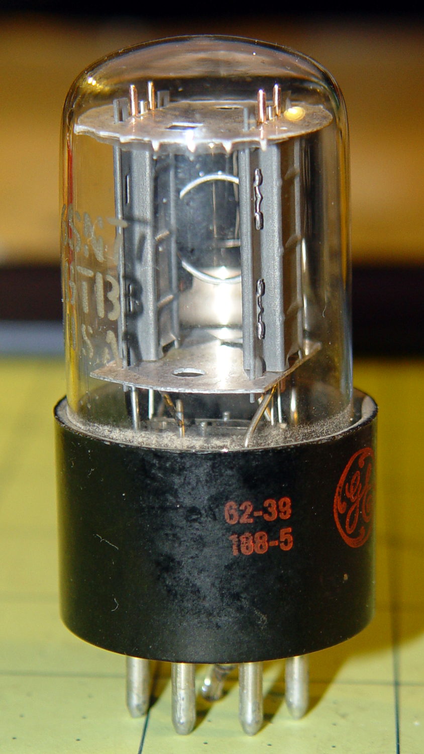
With only a slight loss of historical accuracy, one could light the tube from the top with a Neopixel LED tucked into a similar cap, with power-and-data arriving through a suitably antiqued flying lead. That won’t work on tubes like that 1B3GT with an actual plate terminal at the top, nor with small Noval / miniature 7-pin tubes topped with an evacuation tip, but it’s fine for tubes like this 6SN7GTB:
Obviously, you want a relatively small cap atop the tube, lest the LED visually overwhelm the tube. Some preliminary tests (a.k.a. screwing around) showed that the mica spacer holding the dual triode elements together lights up wonderfully well and diffuses the glow throughout the tube.
Adafruit has relatively large round (and smaller roundish) Neopixel breakout boards, but I bought a bunch of knockoff Neopixels mounted on a 10 mm circular PCB from the usual eBay supplier:

Some PET braid tucked into a snippet of brass tubing dresses up a length of what might once have been audio cable. The braid wants to fray on the ends; confining it with heatstink or brass tubing is mandatory.
That’s a 1 µF ceramic SMD cap soldered between the +5 V and Gnd traces, atop a snippet of Kapton tape, in the hopes that it will help the 100 nF cap (on the other side of the board) tamp down the voltage dunks from PWM current pulses through that long thin wire. The leads come off toward the center to bend neatly upward into the cap.
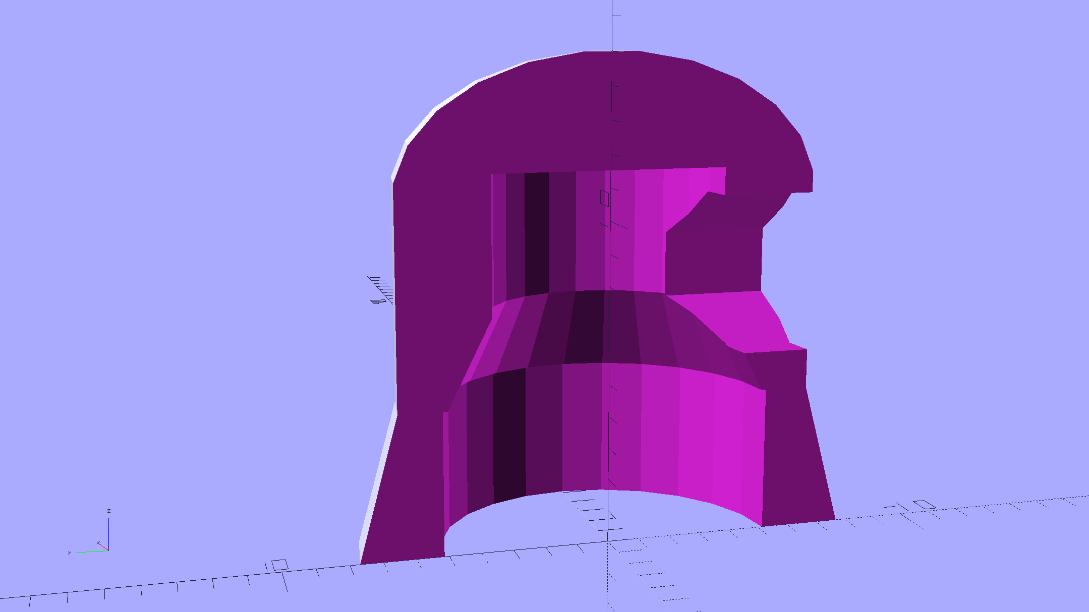
Duplicating that old plate cap on the 1B3GT would be a fool’s errand, so I went full frontal Vader:
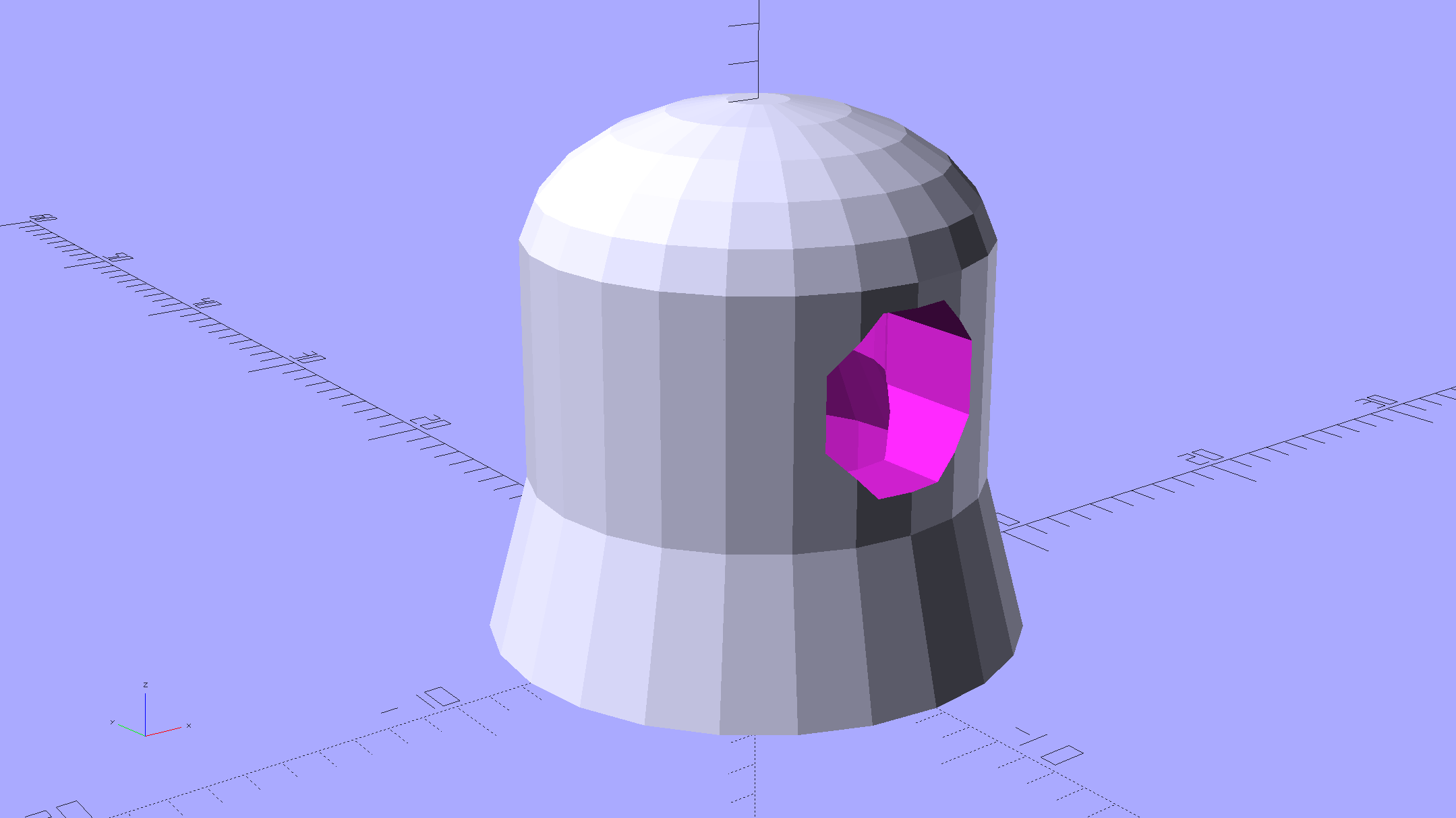
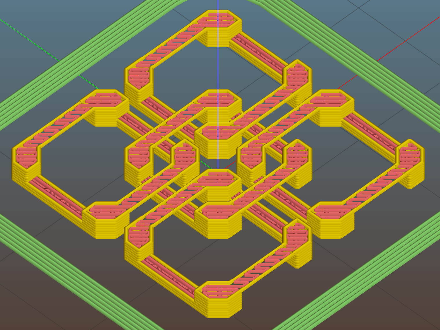
The interior recesses the LED far enough to allow for the tube’s top curvature, with a conical adapter to the smaller wiring channel that allows for more plastic supporting the brass tube:
A glob of epoxy inside the cap anchors the PCB and fuses all the loose ends / floppy wires / braid strands into a solid block that will never come apart again.
It should be printed (or primered and painted) with opaque black or maybe Bakelite Brown, but right now I have cyan PETG and want to see how it plays, soooo:
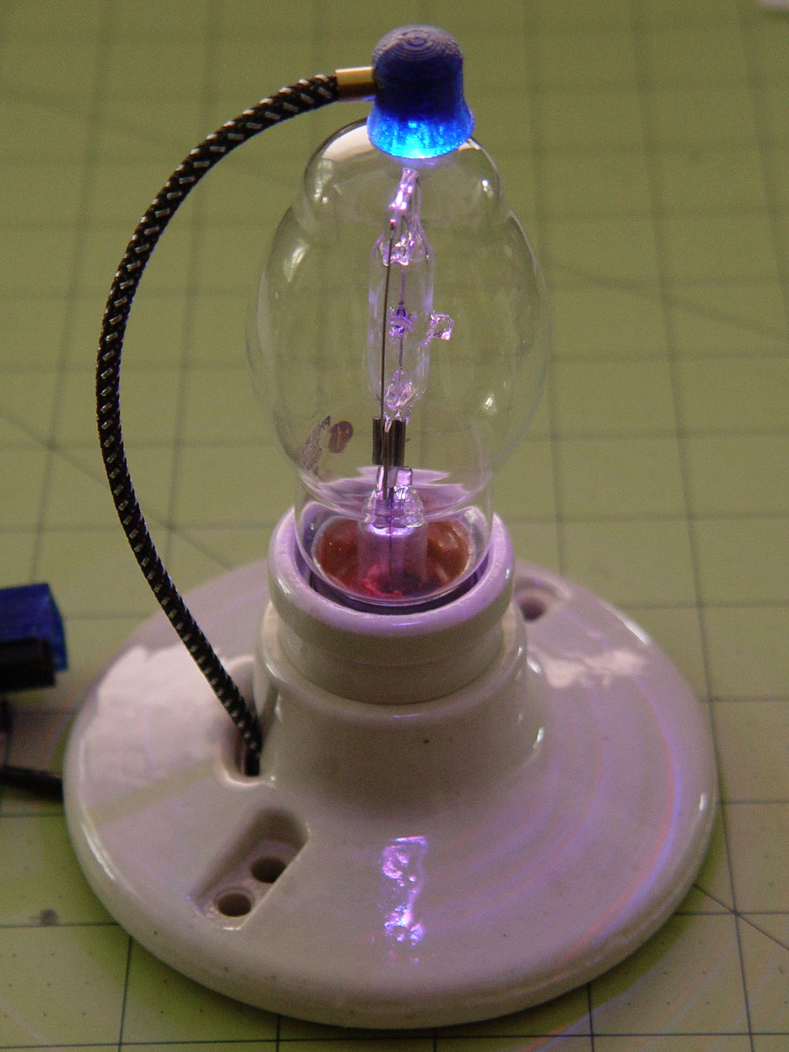
The cap floats in mid-air over a defunct Philips 60 W halogen bulb that I’ve been saving for just such an occasion. Obviously, you must epoxy / glue the cap in place for a permanent display.
The OpenSCAD source code as a Github gist:
| // Vacuum Tube LED Lights | |
| // Ed Nisley KE4ZNU January 2016 | |
| Layout = "Cap"; // Show Build Cap Box Octal Noval Mini7 | |
| Section = true; // cross-section the object | |
| //- Extrusion parameters must match reality! | |
| ThreadThick = 0.25; | |
| ThreadWidth = 0.40; | |
| HoleWindage = 0.2; | |
| Protrusion = 0.1; // make holes end cleanly | |
| inch = 25.4; | |
| function IntegerMultiple(Size,Unit) = Unit * ceil(Size / Unit); | |
| //———————- | |
| // Dimensions | |
| // https://en.wikipedia.org/wiki/Tube_socket#Summary_of_Base_Details | |
| T_NAME = 0; | |
| T_NUMPINS = 1; // Socket specifications | |
| T_PINCIRC = 2; | |
| T_PINDIA = 3; | |
| T_SOCKDIA = 4; | |
| TubeBase = [ | |
| ["Mini7", 8, 9.53, 1.016, 19.0], | |
| ["Octal", 8, 17.45, 2.36, 33.0], | |
| ["Noval",10, 11.89, 1.1016,20.5], | |
| ]; | |
| ID = 0; | |
| OD = 1; | |
| LENGTH = 2; | |
| Pixel = [7.0,10.0,3.0]; // ID = contact patch, OD = PCB dia, LENGTH = overall thickness | |
| //———————- | |
| // Useful routines | |
| module PolyCyl(Dia,Height,ForceSides=0) { // based on nophead's polyholes | |
| Sides = (ForceSides != 0) ? ForceSides : (ceil(Dia) + 2); | |
| FixDia = Dia / cos(180/Sides); | |
| cylinder(r=(FixDia + HoleWindage)/2, | |
| h=Height, | |
| $fn=Sides); | |
| } | |
| //———————- | |
| // Tube cap | |
| CapTube = [4.0,3/16 * inch,10.0]; // brass tube for flying lead to cap LED | |
| CapSize = [Pixel[ID],(Pixel[OD] + 3.0),(CapTube[OD] + 2*Pixel[LENGTH])]; | |
| CapSides = 6*4; | |
| module Cap() { | |
| difference() { | |
| union() { | |
| cylinder(d=CapSize[OD],h=(CapSize[LENGTH]),$fn=CapSides); // main cap body | |
| translate([0,0,CapSize[LENGTH]]) // rounded top | |
| scale([1.0,1.0,0.65]) | |
| sphere(d=CapSize[OD]/cos(180/CapSides),$fn=CapSides); // cos() fixes slight undersize vs cylinder | |
| cylinder(d1=(CapSize[OD] + 2*3*ThreadWidth),d2=CapSize[OD],h=1.5*Pixel[LENGTH],$fn=CapSides); // skirt | |
| } | |
| translate([0,0,-Protrusion]) // bore for wiring to LED | |
| PolyCyl(CapSize[ID],(CapSize[LENGTH] + 3*ThreadThick + Protrusion),CapSides); | |
| translate([0,0,-Protrusion]) // PCB recess with clearance for tube dome | |
| PolyCyl(Pixel[OD],(1.5*Pixel[LENGTH] + Protrusion),CapSides); | |
| translate([0,0,(1.5*Pixel[LENGTH] – Protrusion)]) // step + cone to retain PCB | |
| cylinder(d1=(Pixel[OD]/cos(180/CapSides)),d2=Pixel[ID],h=(Pixel[LENGTH] + Protrusion),$fn=CapSides); | |
| translate([0,0,(CapSize[LENGTH] – CapTube[OD]/(2*cos(180/8)))]) // hole for brass tube holding wire loom | |
| rotate([90,0,0]) rotate(180/8) | |
| PolyCyl(CapTube[OD],CapSize[OD],8); | |
| } | |
| } | |
| //———————- | |
| // Build it | |
| if (Layout == "Cap") { | |
| if (Section) | |
| difference() { | |
| Cap(); | |
| translate([-CapSize[OD],0,CapSize[LENGTH]]) | |
| cube([2*CapSize[OD],2*CapSize[OD],3*CapSize[LENGTH]],center=true); | |
| } | |
| else | |
| Cap(); | |
| } | |
| if (Layout == "Build") { | |
| Cap(); | |
| Spigot(); | |
| } |