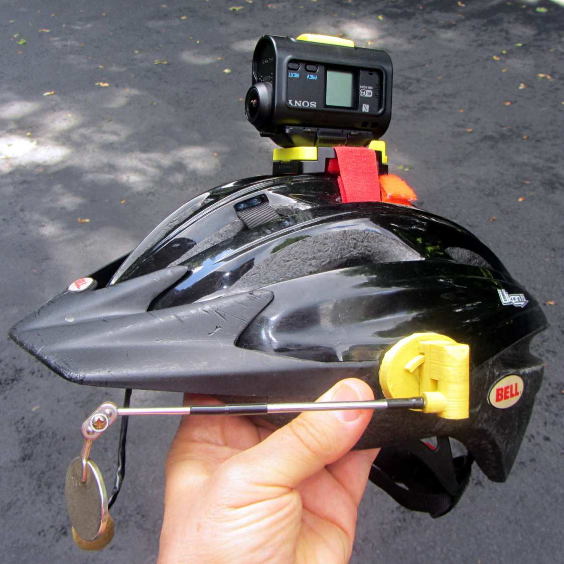
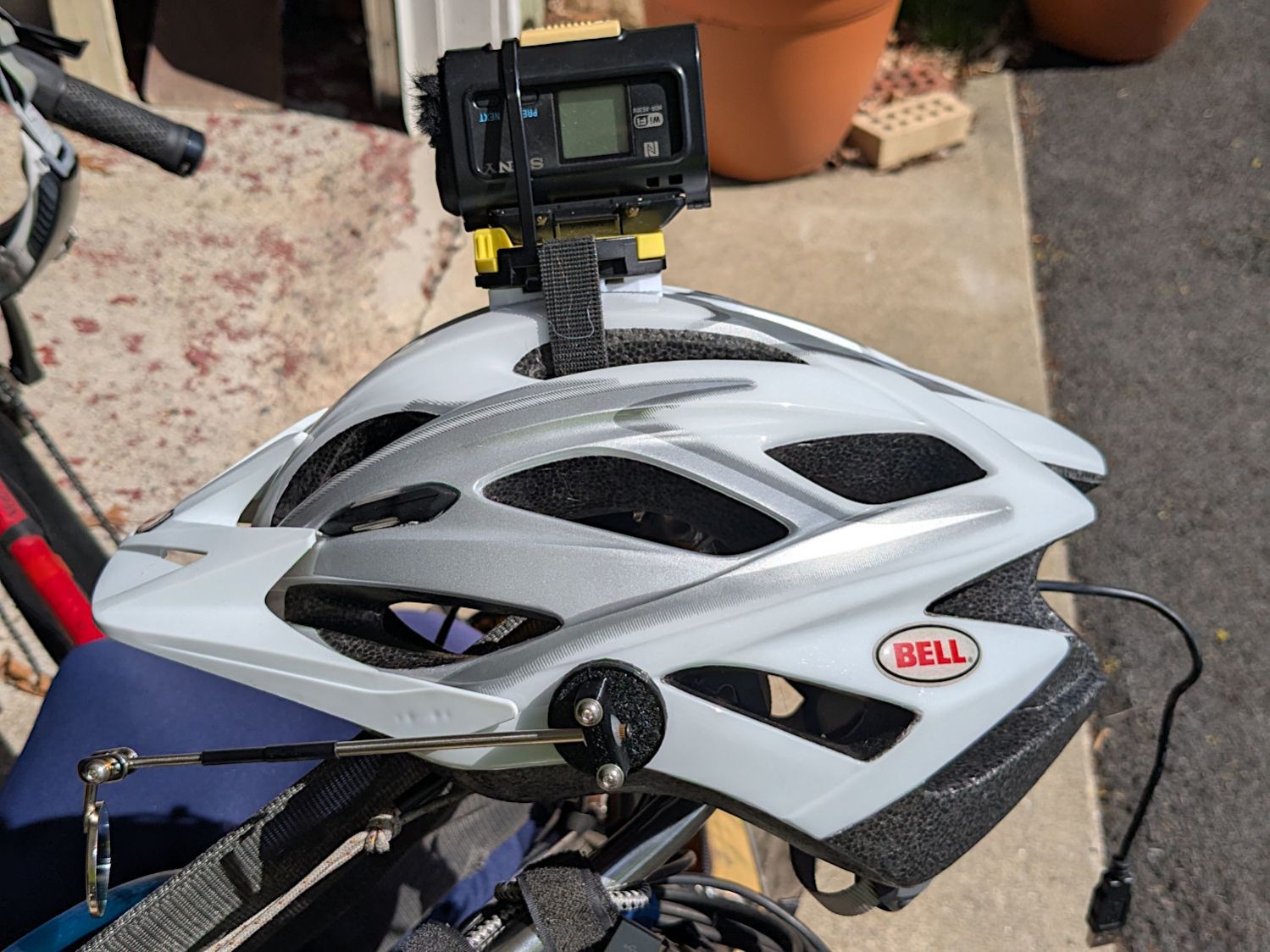
The original shower head being too far overhead for Mary’s reach, I installed a Delta ProClean Shower Head which would also be too high. It has a hose, which means I can adjust the height:
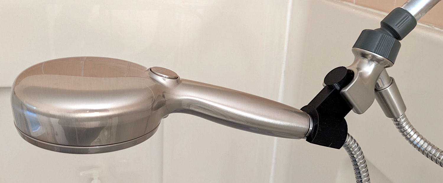
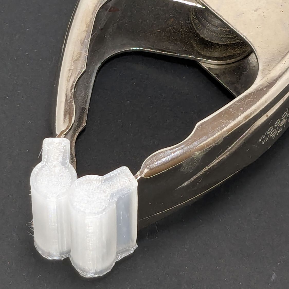
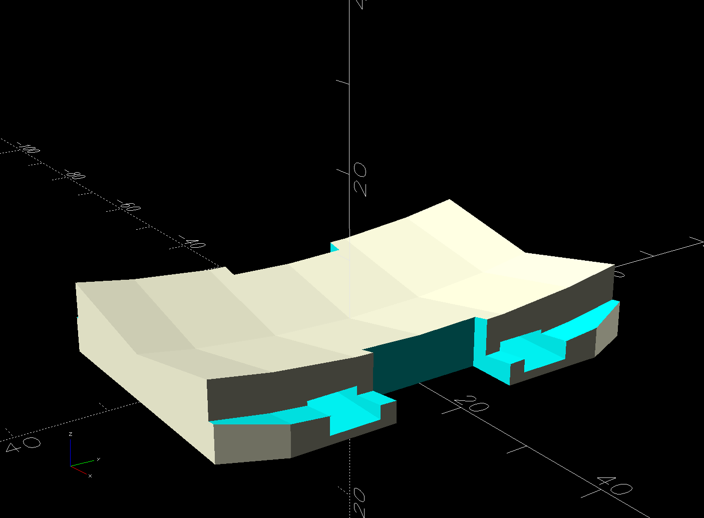
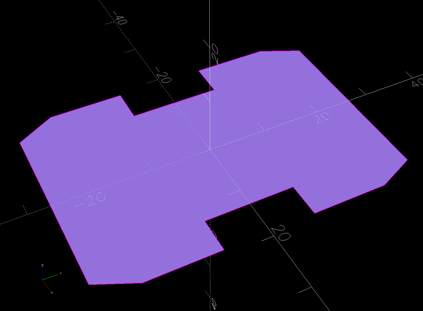
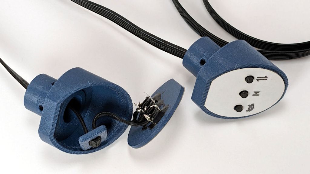
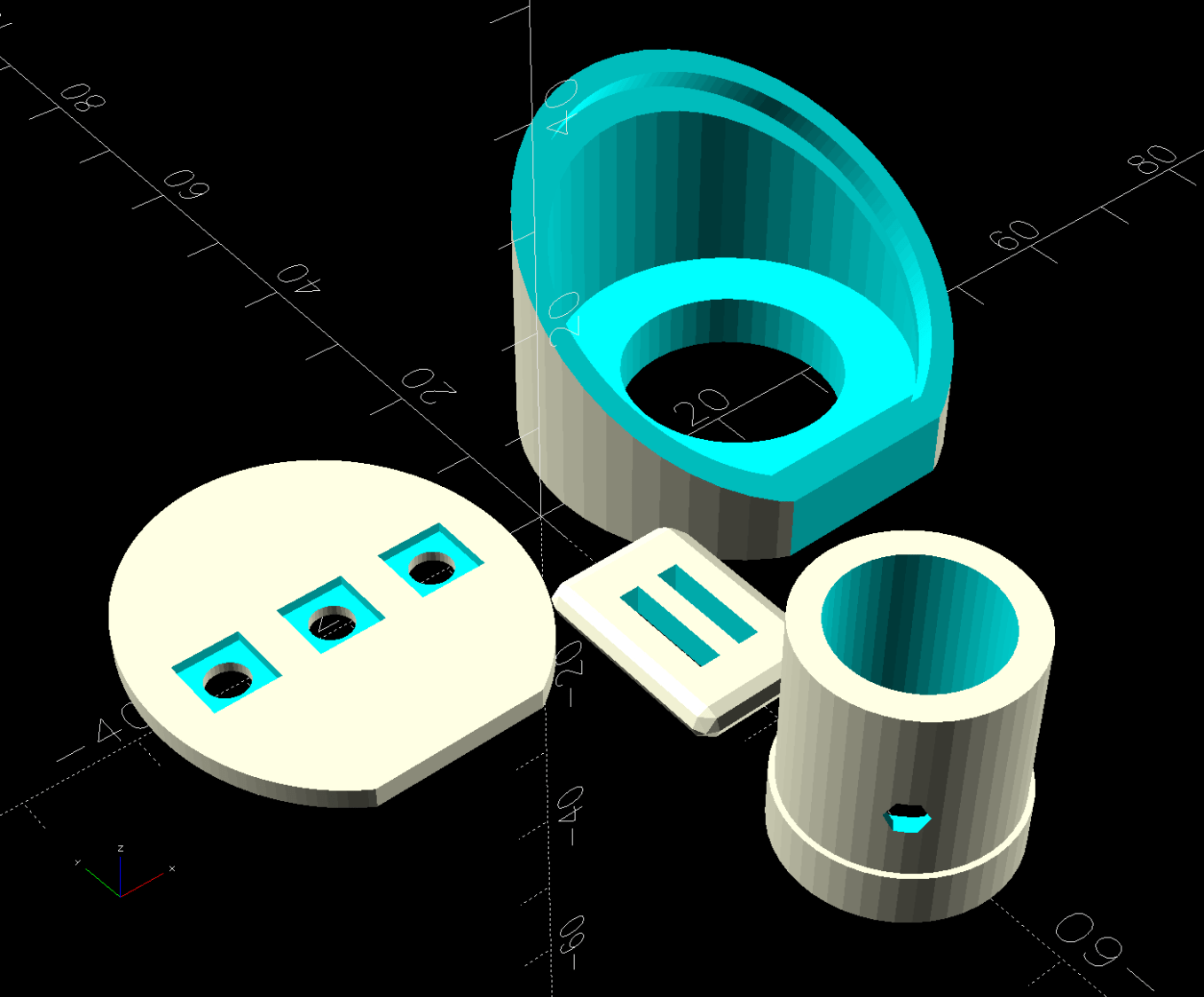
The InterWebs offer several 3D-printable versions of such a thing, but Delta offers many different shower heads, some of which are visually (to my eyes, anyway) indistinguishable from the 75740SN you see here. The model I tried did not fit the holder I have, so I conjured one from the vasty digital deep:
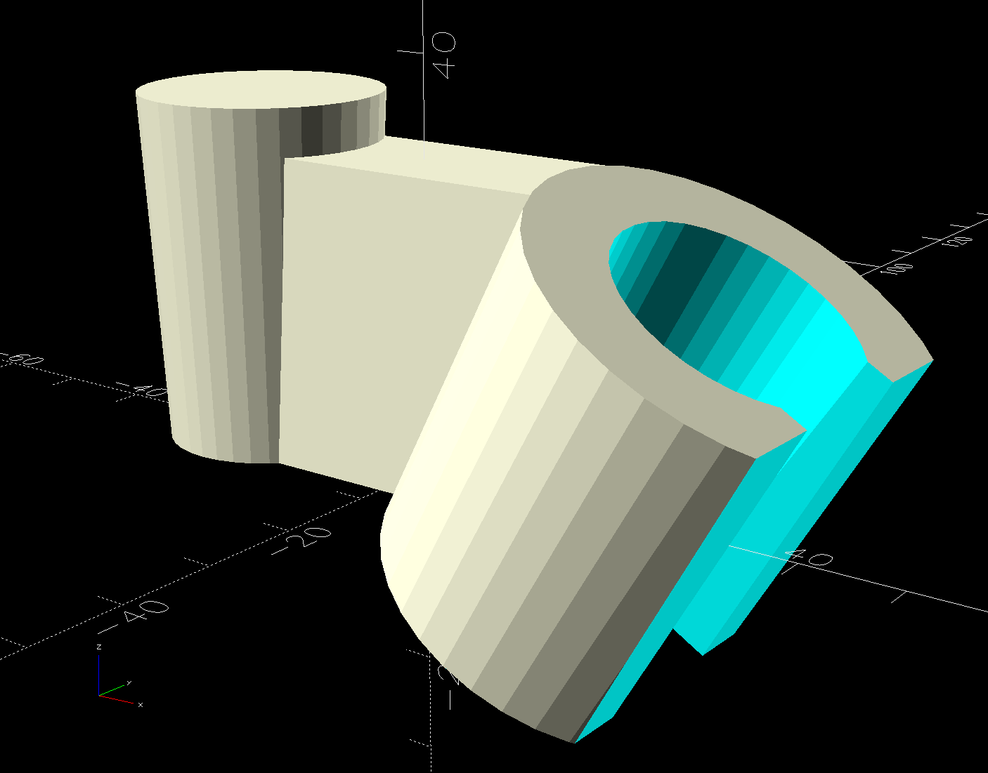
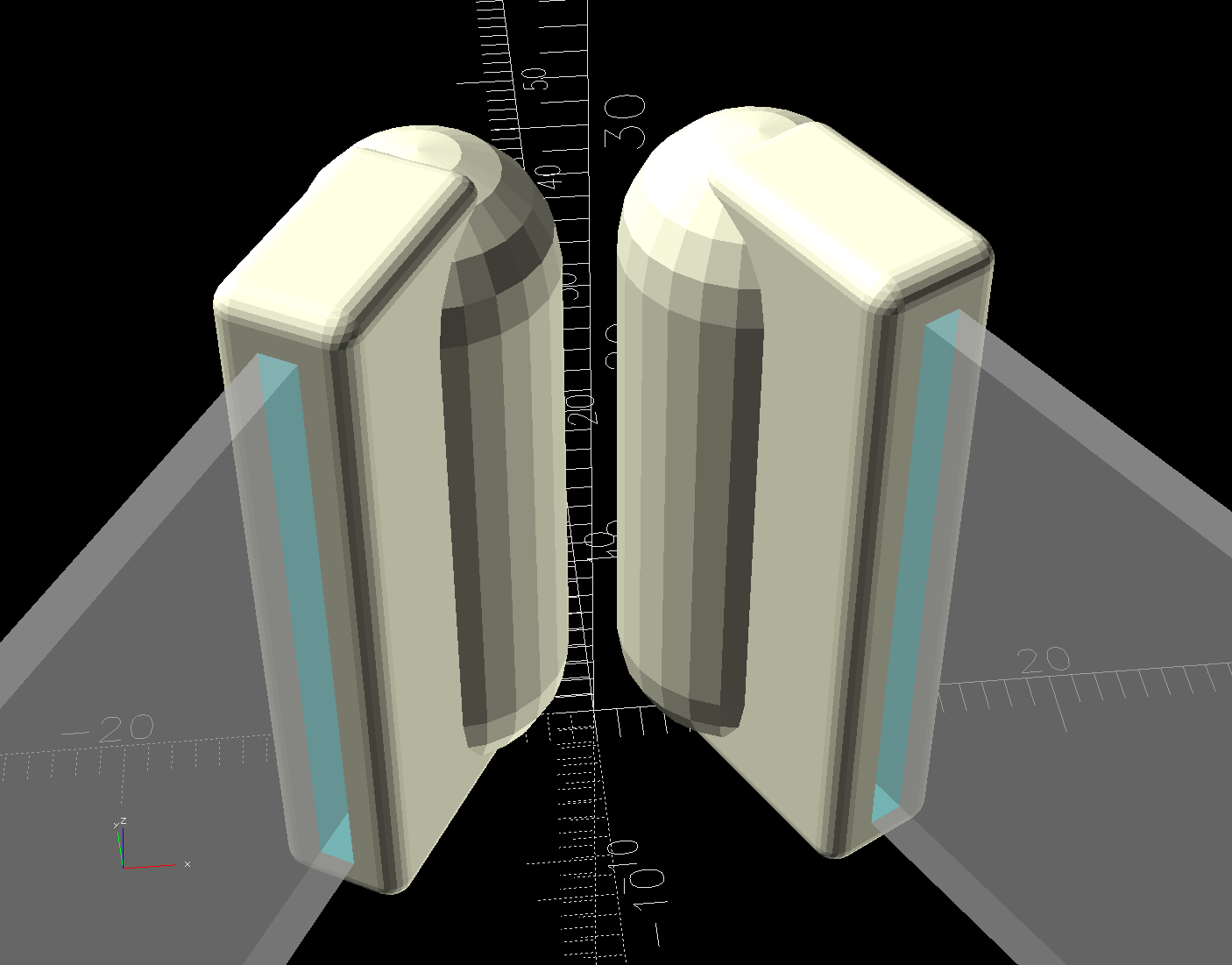
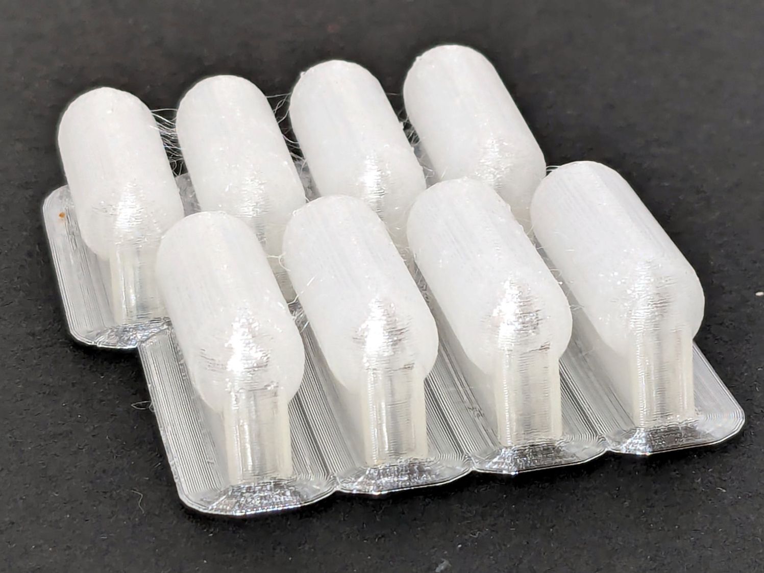
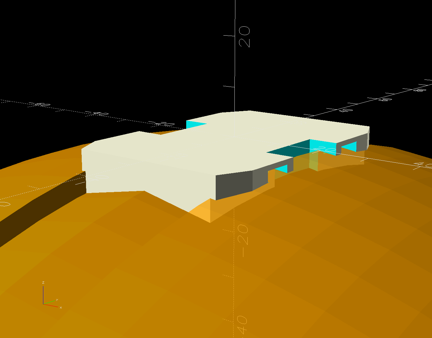
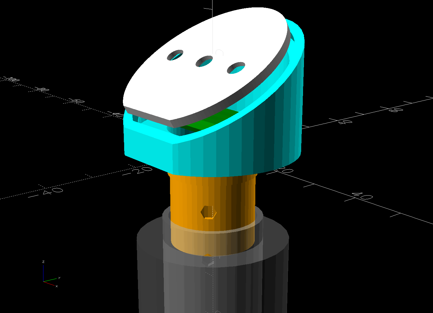
It builds standing on that tidy cutoff:

Despite PrusaSlicer’s kvetching about the “collapsing overhang” inside the socket, it came out fine.
The shower head is still slightly too high for her, but now I can print another one with a longer offset and a slightly smaller plug to fit deeper in the OEM socket.
Worst case, there’s a wall-mounted holder to put the shower head at shoulder height.
The OpenSCAD source code as a GitHub Gist:
| // Delta shower head holder extension | |
| // Ed Nisley – KE4ZNU | |
| // 2025-05-02 | |
| include <BOSL2/std.scad> | |
| Layout = "Show"; // [Show,Build,Plug,Socket,Connector] | |
| MountAngle = 30; // between OEM and new holder | |
| MountOffset = 20.0; | |
| /* [Hidden] */ | |
| HoleWindage = 0.2; | |
| Protrusion = 0.1; | |
| NumSides = 3*3*4; | |
| ID = 0; | |
| OD = 1; | |
| LENGTH = 2; | |
| Insert = [21.0,24.5,35.0]; // hose connector taper | |
| PlugSize = Insert + [-0.3,-0.3,0]; // … for better fit in OEM holder | |
| Slot = [Insert[OD],14.6,3*Insert[LENGTH]]; // slot on OEM holder, arbitrary length | |
| WallThick = 8.0; // holder wall thickness | |
| Radius = 3.0; // shapely rounding | |
| $fn=NumSides; | |
| //———- | |
| // Define Shapes | |
| module Plug() { | |
| cyl(l=Insert[LENGTH],d1=PlugSize[ID],d2=PlugSize[OD],anchor=BOTTOM); | |
| } | |
| module Socket() { | |
| difference() { | |
| tube(l=Insert[LENGTH],id1=Insert[ID],id2=Insert[OD],wall=WallThick,anchor=BOTTOM); | |
| cuboid(Slot + [0,1.0,0],anchor=LEFT+CENTER); | |
| right(Insert[OD]/2) | |
| cube([Insert[OD],Insert[OD] + 2*WallThick,3*Insert[LENGTH]],anchor=LEFT+CENTER); | |
| } | |
| } | |
| module Connector() { | |
| difference() { | |
| left(MountOffset) | |
| cuboid([MountOffset + Insert[LENGTH]*sin(MountAngle),Slot.y,Insert[LENGTH]*cos(MountAngle)], | |
| anchor=LEFT+BOTTOM); | |
| yrot(MountAngle) right(Insert[ID]/2 + WallThick) | |
| cyl(l=Insert[LENGTH],d1=Insert[ID] + 2*WallThick,d2=Insert[OD] + 2*WallThick,anchor=BOTTOM); | |
| } | |
| } | |
| module Adapter() { | |
| union() { | |
| left(MountOffset) | |
| Plug(); | |
| yrot(MountAngle) right((Insert[ID] + 2*WallThick)/2) | |
| Socket(); | |
| Connector(); | |
| } | |
| } | |
| //———- | |
| // Build things | |
| if (Layout == "Plug") | |
| Plug(); | |
| if (Layout == "Socket") | |
| Socket(); | |
| if (Layout == "Connector") | |
| Connector(); | |
| if (Layout == "Show") | |
| Adapter(); | |
| if (Layout == "Build") | |
| up(Insert[ID]/2 + 1*WallThick + Insert[OD]/2) | |
| yrot(90-MountAngle) | |
| Adapter(); |