The Smell of Molten Projects in the Morning

Ed Nisley's Blog: Shop notes, electronics, firmware, machinery, 3D printing, laser cuttery, and curiosities. Contents: 100% human thinking, 0% AI slop.

Category: Software

General-purpose computers doing something specific

  • HP 7475A Plotter: Coordinate Pruning

    The original SuperFormula equation produces points in polar coordinates, which the Chiplotle library converts to the rectilinear format more useful with Cartesian plotters. I’ve been feeding the equation with 10001 angular values (10 passes around the paper, with 1000 points per pass, plus one more point to close the pattern), which means the angle changes by 3600°/10000 = 0.36° per point. Depending on the formula’s randomly chosen parameters, each successive point can move the plotter pen by almost nothing to several inches.

    On the “almost nothing” end of the scale, the plotter slows to a crawl while the serial interface struggles to feed the commands. Given that you can’t see the result, why send the commands?

    Computing point-to-point distances goes more easily in rectilinear coordinates, so I un-tweaked my polar-modified superformula function to return the points in rectangular coordinates. I’d originally thought a progressive scaling factor would be interesting, but it never happened.

    The coordinate pruning occurs in the supershape function, which now contains a loop to scan through the incoming list of points from the  superformula function and add a point to the output path only when it differs by enough from the most recently output point:

        path = []
        path.append(Coordinate(width * points[0][0], height * points[0][1]))
        outi = 0
        xp, yp = points[outi][0], points[outi][1]
        for i in range(len(points))[1:]:
            x,y = width * points[i][0], height * points[i][1]
            dist = sqrt(pow(x - xp,2) + pow(y - yp,2))
            if dist > 60 :
              path.append(Coordinate(x, y))
              outi = i
              xp, yp = x, y
    
        path.append(Coordinate(width * points[-1][0], height * points[-1][1]))
        print "Pruned",len(points),"to",len(path),"points"
    

    The first and last points always go into the output list; the latter might be duplicated, but that doesn’t matter.

    Note that you can’t prune the list by comparing successive points, because then you’d jump directly from the start of a series of small motions to their end. The idea is to step through the small motions in larger units that, with a bit of luck, won’t be too ugly.

    The width and height values scale the XY coordinates to fill either A or B paper sheets, with units of “Plotter Units” = 40.2 PU/mm = 1021 PU/inch. You can scale those in various ways to fit various output sizes within the sheets, but I use the defaults that fill the entire sheets with a reasonable margin. As a result, the magic number 60 specifies 60 Plotter Units; obviously, it should have a suitable name.

    Pruning to 40 PU = 1.0 mm (clicky for more dots, festooned with over-compressed JPEG artifacts):

    Plot pruned to 40 PU
    Plot pruned to 40 PU

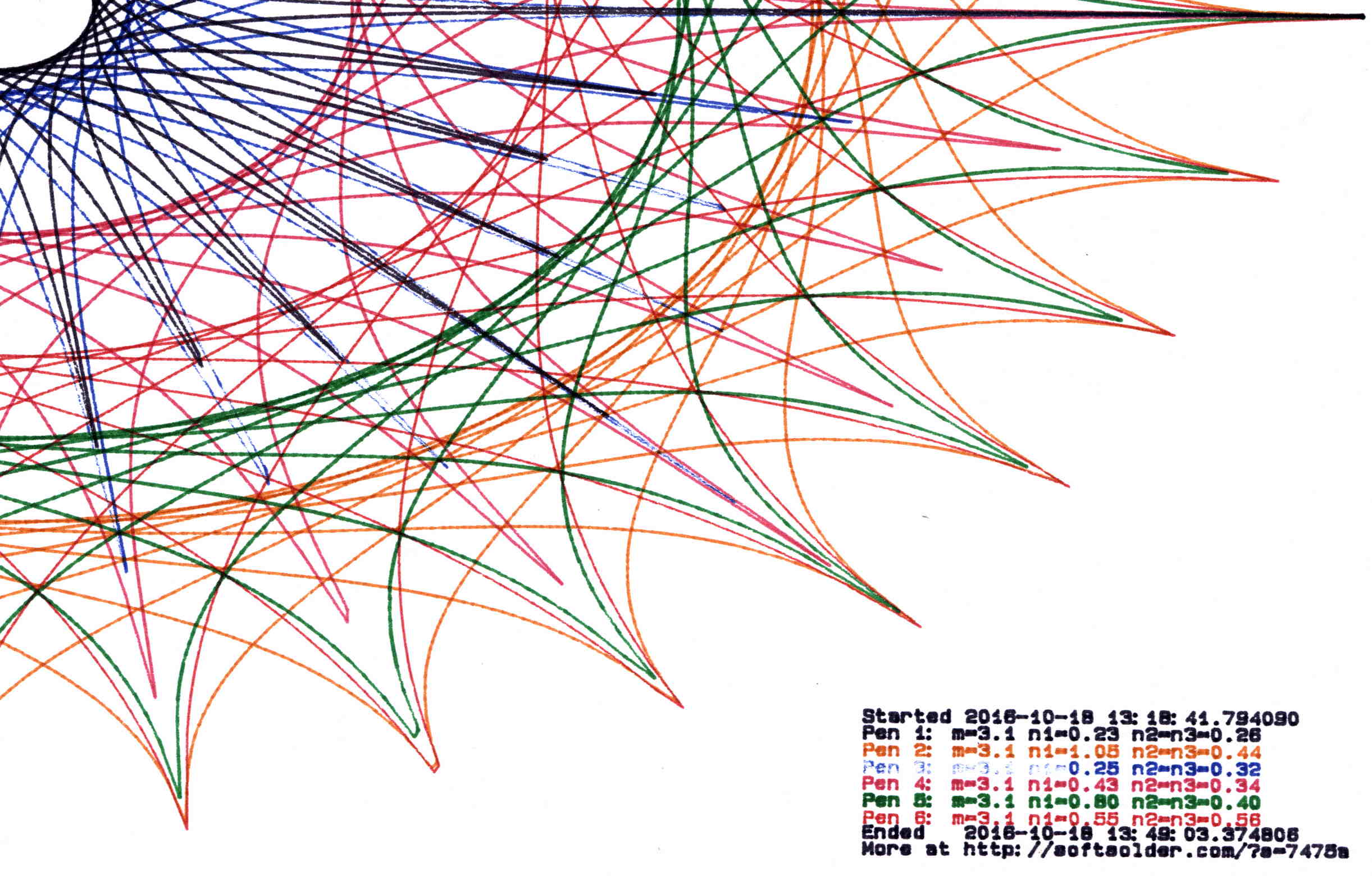
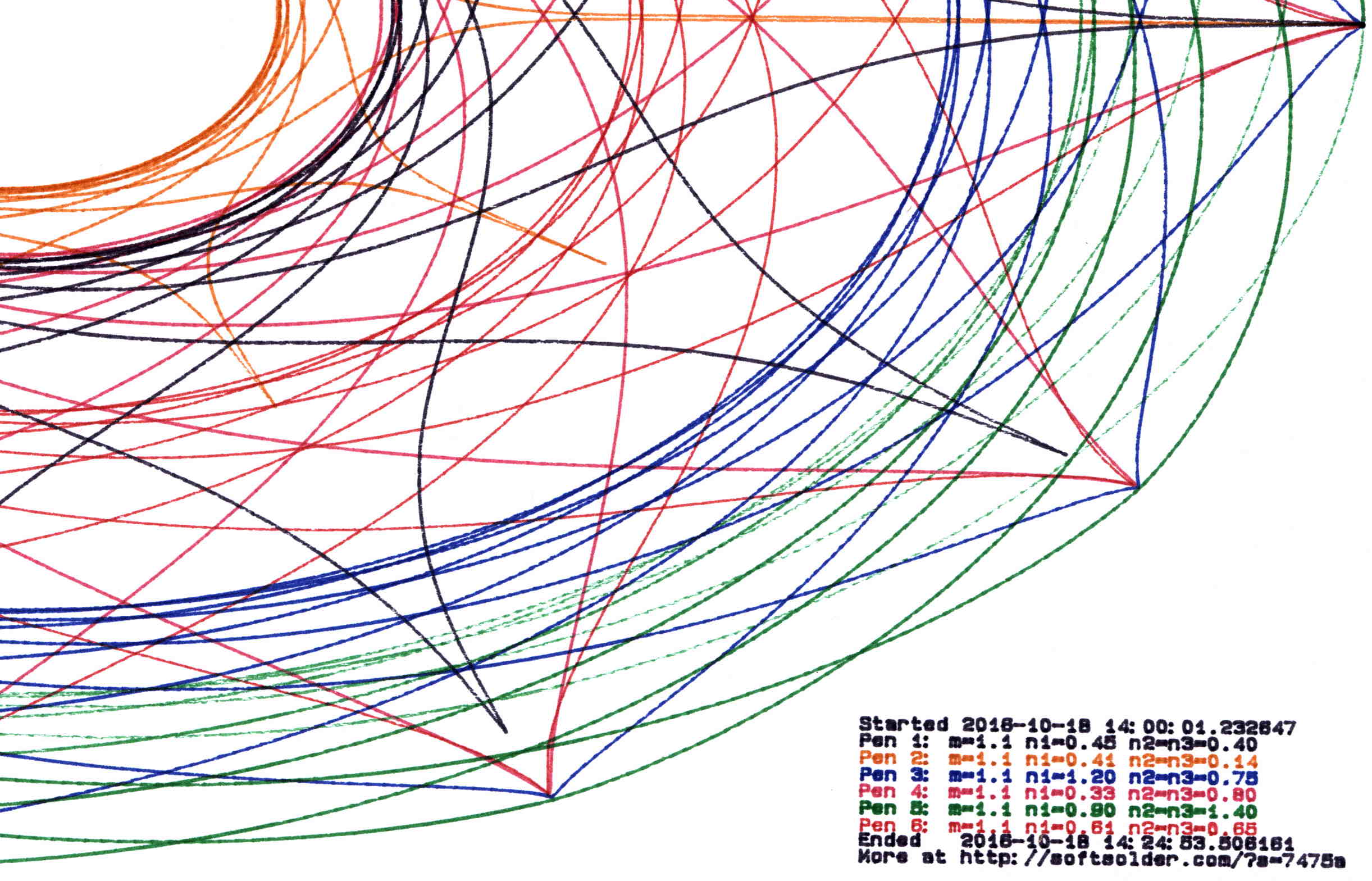
    Pruning to 60 PU = 1.5 mm:

    Plot pruned to 60 PU
    Plot pruned to 60 PU

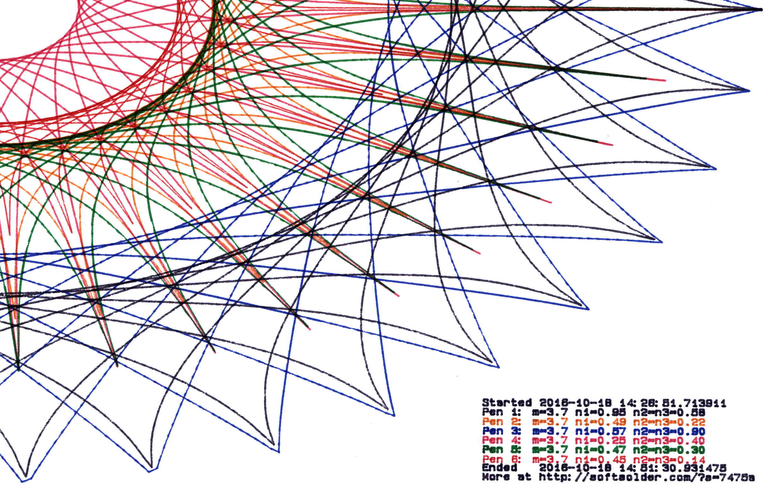
    Pruning to 80 PU = 2.0 mm:

    Plot pruned to 80 PU
    Plot pruned to 80 PU

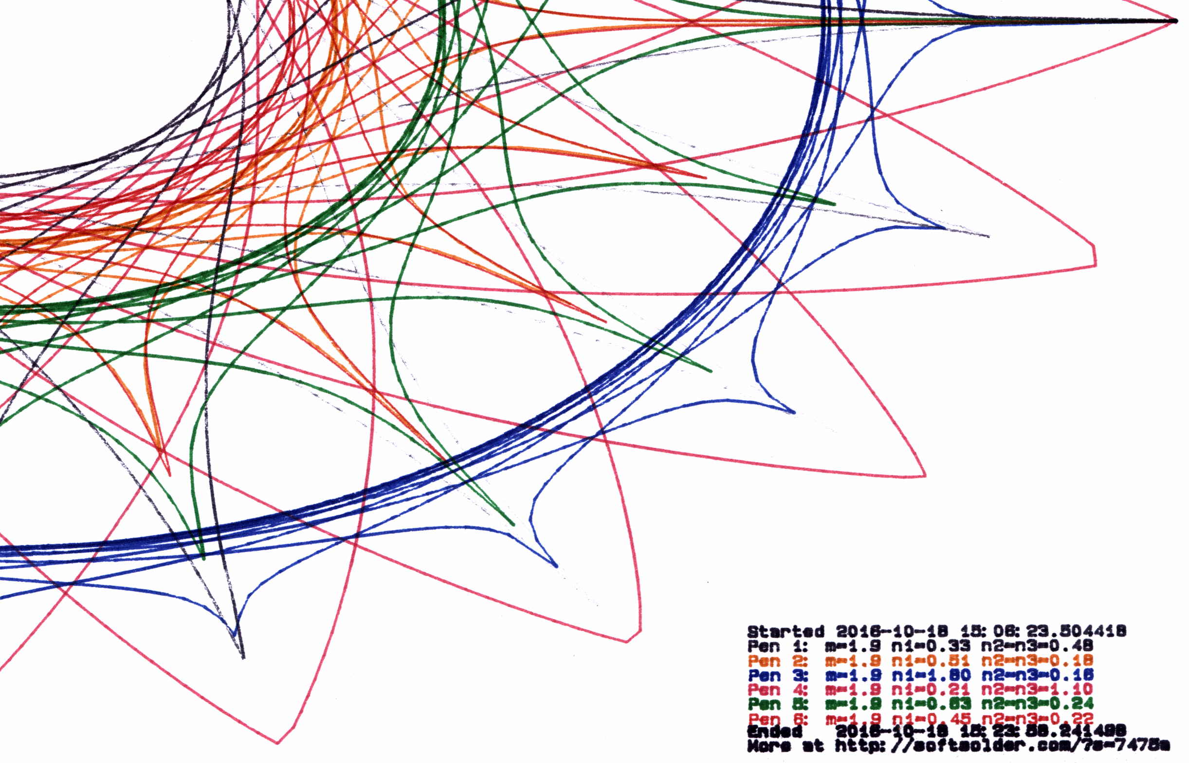
    Pruning to 120 PU = 3.0 mm:

    Plot pruned to 120 PU
    Plot pruned to 120 PU

    All four of those plots have the same pens in the same order, although I refilled a few of them in flight.

    By and large, up through 80 PU there’s not much visual difference, although you can definitely see the 3 mm increments at 120 PU. However, the plotting time drops from just under an hour for each un-pruned plot to maybe 15 minutes with 120 PU pruning, with 60 PU producing very good results at half an hour.

    Comparing the length of the input point lists to the pruned output path lists, including some pruning values not shown above:

    Prune 20
    1 - m: 5.3, n1: 0.15, n2=n3: 0.80
    Pruned 10001 to 4856 points
    2 - m: 5.3, n1: 0.23, n2=n3: 0.75
    Pruned 10001 to 5545 points
    3 - m: 5.3, n1: 1.15, n2=n3: 0.44
    Pruned 10001 to 6218 points
    4 - m: 5.3, n1: 0.41, n2=n3: 1.50
    Pruned 10001 to 7669 points
    5 - m: 5.3, n1: 0.29, n2=n3: 0.95
    Pruned 10001 to 6636 points
    6 - m: 5.3, n1: 0.95, n2=n3: 0.16
    Pruned 10001 to 5076 points
    
    Prune 40
    1 - m: 3.1, n1: 0.23, n2=n3: 0.26
    Pruned 10001 to 2125 points
    2 - m: 3.1, n1: 1.05, n2=n3: 0.44
    Pruned 10001 to 5725 points
    3 - m: 3.1, n1: 0.25, n2=n3: 0.32
    Pruned 10001 to 2678 points
    4 - m: 3.1, n1: 0.43, n2=n3: 0.34
    Pruned 10001 to 4040 points
    5 - m: 3.1, n1: 0.80, n2=n3: 0.40
    Pruned 10001 to 5380 points
    6 - m: 3.1, n1: 0.55, n2=n3: 0.56
    Pruned 10001 to 5424 points
    
    Prune 60
    1 - m: 1.1, n1: 0.45, n2=n3: 0.40
    Pruned 10001 to 2663 points
    2 - m: 1.1, n1: 0.41, n2=n3: 0.14
    Pruned 10001 to 1706 points
    3 - m: 1.1, n1: 1.20, n2=n3: 0.75
    Pruned 10001 to 4446 points
    4 - m: 1.1, n1: 0.33, n2=n3: 0.80
    Pruned 10001 to 3036 points
    5 - m: 1.1, n1: 0.90, n2=n3: 1.40
    Pruned 10001 to 4723 points
    6 - m: 1.1, n1: 0.61, n2=n3: 0.65
    Pruned 10001 to 3601 points
    
    Prune 80
    1 - m: 3.7, n1: 0.95, n2=n3: 0.58
    Pruned 10001 to 3688 points
    2 - m: 3.7, n1: 0.49, n2=n3: 0.22
    Pruned 10001 to 2258 points
    3 - m: 3.7, n1: 0.57, n2=n3: 0.90
    Pruned 10001 to 3823 points
    4 - m: 3.7, n1: 0.25, n2=n3: 0.40
    Pruned 10001 to 2161 points
    5 - m: 3.7, n1: 0.47, n2=n3: 0.30
    Pruned 10001 to 2532 points
    6 - m: 3.7, n1: 0.45, n2=n3: 0.14
    Pruned 10001 to 1782 points
    
    Prune 120
    1 - m: 1.9, n1: 0.33, n2=n3: 0.48
    Pruned 10001 to 1561 points
    2 - m: 1.9, n1: 0.51, n2=n3: 0.18
    Pruned 10001 to 1328 points
    3 - m: 1.9, n1: 1.80, n2=n3: 0.16
    Pruned 10001 to 2328 points
    4 - m: 1.9, n1: 0.21, n2=n3: 1.10
    Pruned 10001 to 1981 points
    5 - m: 1.9, n1: 0.63, n2=n3: 0.24
    Pruned 10001 to 1664 points
    6 - m: 1.9, n1: 0.45, n2=n3: 0.22
    Pruned 10001 to 1290 points
    

    Eyeballometrically, 60 PU pruning halves the number of plotted points, so the average data rate jumps from 9600 b/s to 19.2 kb/s. Zowie!

    Most of the pruning occurs near the middle of the patterns, where the pen slows to a crawl. Out near the spiky rim, where the points are few & far between, there’s no pruning at all. Obviously, quantizing a generic plot to 1.5 mm would produce terrible results; in this situation, the SuperFormula produces smooth curves (apart from those spikes) that look just fine.

    The Python source code as a GitHub Gist:

    # Adapted from Chiplotle plotter library:
    # http://cmc.music.columbia.edu/chiplotle/
    from chiplotle import *
    from math import *
    from datetime import *
    from time import *
    from types import *
    import random
    def supershape(width, height, m, n1, n2, n3,
    point_count=10 * 1000, percentage=1.0, a=1.0, b=1.0, travel=None):
    '''Supershape, generated using the superformula first proposed
    by Johan Gielis.
    – `points_count` is the total number of points to compute.
    – `travel` is the length of the outline drawn in radians.
    3.1416 * 2 is a complete cycle.
    modified to prune short plotter motions – Ed Nisley KE4ZNU – October 2016
    '''
    travel = travel or (10 * 2 * pi)
    # compute points…
    phis = [i * travel / point_count
    for i in range(1 + int(point_count * percentage))]
    points = [tools.mathtools.superformula(a, b, m, n1, n2, n3, x) for x in phis]
    # scale and prune short motions
    path = []
    path.append(Coordinate(width * points[0][0], height * points[0][1]))
    outi = 0
    xp, yp = points[outi][0], points[outi][1]
    for i in range(len(points))[1:]:
    x,y = width * points[i][0], height * points[i][1]
    dist = sqrt(pow(x – xp,2) + pow(y – yp,2))
    if dist > 60 :
    path.append(Coordinate(x, y))
    outi = i
    xp, yp = x, y
    path.append(Coordinate(width * points[-1][0], height * points[-1][1]))
    print " Pruned",len(points),"to",len(path),"points"
    return Path(path)
    # Run Superformula plots
    if __name__ == '__main__':
    override = False
    plt = instantiate_plotters()[0]
    # plt.write('IN;')
    if plt.margins.soft.width < 11000: # A=10365 B=16640
    maxplotx = (plt.margins.soft.width / 2) – 100
    maxploty = (plt.margins.soft.height / 2) – 150
    legendx = maxplotx – 2900
    legendy = -(maxploty – 750)
    tscale = 0.45
    numpens = 4
    # prime/10 = number of spikes
    m_values = [n / 10.0 for n in [11, 13, 17, 19, 23]]
    # ring-ness 0.1 to 2.0, higher is larger
    n1_values = [
    n / 100.0 for n in range(55, 75, 2) + range(80, 120, 5) + range(120, 200, 10)]
    else:
    maxplotx = plt.margins.soft.width / 2
    maxploty = plt.margins.soft.height / 2
    legendx = maxplotx – 3000
    legendy = -(maxploty – 900)
    tscale = 0.45
    numpens = 6
    m_values = [n / 10.0 for n in [11, 13, 17, 19, 23, 29, 31,
    37, 41, 43, 47, 53, 59]] # prime/10 = number of spikes
    # ring-ness 0.1 to 2.0, higher is larger
    n1_values = [
    n / 100.0 for n in range(15, 75, 2) + range(80, 120, 5) + range(120, 200, 10)]
    print " Max: ({},{})".format(maxplotx, maxploty)
    # spiky-ness 0.1 to 2.0, higher is spiky-er (mostly)
    n2_values = [
    n / 100.0 for n in range(10, 60, 2) + range(65, 100, 5) + range(110, 200, 10)]
    plt.write(chr(27) + '.H200:') # set hardware handshake block size
    plt.set_origin_center()
    # scale based on B size characters
    plt.write(hpgl.SI(tscale * 0.285, tscale * 0.375))
    # slow speed for those abrupt spikes
    plt.write(hpgl.VS(10))
    while True:
    # standard loadout has pen 1 = fine black
    plt.write(hpgl.PA([(legendx, legendy)]))
    pen = 1
    plt.select_pen(pen)
    plt.write(hpgl.PA([(legendx, legendy)]))
    plt.write(hpgl.LB("Started " + str(datetime.today())))
    if override:
    m = 4.1
    n1_list = [1.15, 0.90, 0.25, 0.59, 0.51, 0.23]
    n2_list = [0.70, 0.58, 0.32, 0.28, 0.56, 0.26]
    else:
    m = random.choice(m_values)
    n1_list = random.sample(n1_values, numpens)
    n2_list = random.sample(n2_values, numpens)
    pen = 1
    for n1, n2 in zip(n1_list, n2_list):
    n3 = n2
    print "{0} – m: {1:.1f}, n1: {2:.2f}, n2=n3: {3:.2f}".format(pen, m, n1, n2)
    plt.select_pen(pen)
    plt.write(hpgl.PA([(legendx, legendy – 100 * pen)]))
    plt.write(
    hpgl.LB("Pen {0}: m={1:.1f} n1={2:.2f} n2=n3={3:.2f}".format(pen, m, n1, n2)))
    e = supershape(maxplotx, maxploty, m, n1, n2, n3)
    plt.write(e)
    pen = pen + 1 if (pen % numpens) else 1
    pen = 1
    plt.select_pen(pen)
    plt.write(hpgl.PA([(legendx, legendy – 100 * (numpens + 1))]))
    plt.write(hpgl.LB("Ended " + str(datetime.today())))
    plt.write(hpgl.PA([(legendx, legendy – 100 * (numpens + 2))]))
    plt.write(hpgl.LB("More at https://softsolder.com/?s=7475a&quot;))
    plt.select_pen(0)
    plt.write(hpgl.PA([(-maxplotx,maxploty)]))
    print "Waiting for plotter… ignore timeout errors!"
    sleep(40)
    while NoneType is type(plt.status):
    sleep(5)
    print "Load more paper, then …"
    print " … Press ENTER on the plotter to continue"
    plt.clear_digitizer()
    plt.digitize_point()
    plotstatus = plt.status
    while (NoneType is type(plotstatus)) or (0 == int(plotstatus) & 0x04):
    plotstatus = plt.status
    print "Digitized: " + str(plt.digitized_point)

  • ATM Error Message

    Saw this after fat-fingering my PIN at a drive-up ATM:

    ATM Screen Display Error Message
    ATM Screen Display Error Message

    That’s off-putting, isn’t it?

  • Reticle Guide for Ruler Quilting

    I made the pencil guides to help Mary design ruler quilting patterns, but sometimes she must line up the ruler with a feature on an existing pattern. To that end, we now have a reticle guide:

    Ruler Adapters - pencil guide and reticle
    Ruler Adapters – pencil guide and reticle

    The general idea is that it’s easier to see the pattern on paper through the crosshair than through a small hole. You put the button over a feature, align the reticle, put the ruler against the button, replace it with pencil guide, and away you go.

    The solid model looks much more lively than you’d expect:

    Ruler Adapter - reticle - Slic3r preview
    Ruler Adapter – reticle – Slic3r preview

    Printing up a pair of each button produces the same surface finish as before; life is good!

    The OpenSCAD source code as a GitHub Gist:

    // Quilting Ruler Adapters
    // Ed Nisley KE4ZNU October 2016
    //- Extrusion parameters must match reality!
    ThreadThick = 0.25;
    ThreadWidth = 0.40;
    HoleWindage = 0.2;
    Protrusion = 0.1; // make holes end cleanly
    inch = 25.4;
    function IntegerMultiple(Size,Unit) = Unit * ceil(Size / Unit);
    //———-
    // Dimensions
    ID = 0;
    OD = 1;
    LENGTH = 2;
    Offset = 0.25 * inch;
    Template = [2.0,2*Offset,3.0];
    NumSides = 16*4;
    HoleSides = 8;
    //———————-
    // Useful routines
    module PolyCyl(Dia,Height,ForceSides=0) { // based on nophead's polyholes
    Sides = (ForceSides != 0) ? ForceSides : (ceil(Dia) + 2);
    FixDia = Dia / cos(180/Sides);
    cylinder(d=(FixDia + HoleWindage),h=Height,$fn=Sides);
    }
    //———-
    // Build them
    translate([-Template[OD],0,0])
    difference() {
    cylinder(d=Template[OD],h=Template[LENGTH],$fn=NumSides);
    translate([0,0,-Template[LENGTH]])
    PolyCyl(Template[ID],3*Template[LENGTH],HoleSides);
    translate([0,0,-Protrusion])
    cylinder(d1=2*Template[ID],d2=Template[ID],h=Template[LENGTH]/3 + Protrusion,$fn=HoleSides);
    translate([0,0,Template[LENGTH] + Protrusion])
    mirror([0,0,1])
    cylinder(d1=2*Template[ID],d2=Template[ID],h=Template[LENGTH]/3 + Protrusion,$fn=HoleSides);
    }
    translate([Template[OD],0,0])
    difference() {
    cylinder(d=Template[OD],h=Template[LENGTH],$fn=NumSides);
    for (a=[45,135])
    rotate(a)
    cube([0.70*Template[OD],0.15*Template[OD],3*Template[LENGTH]],center=true);
    }
  • Pencil Guides for Ruler Quilting

    Mary has been doing Ruler Quilting and wanted a pencil guide (similar to the machine’s ruler foot) to let her sketch layouts before committing stitches to fabric. The general idea is to offset the pencil by 1/4 inch from the edge of the ruler:

    Ruler Adapter - solid model
    Ruler Adapter – solid model

    That was easy.

    Print three to provide a bit of cooling time and let her pass ’em around at her next quilting bee:

    Ruler Adapter - Slic3r preview
    Ruler Adapter – Slic3r preview

    Her favorite doodling pencil shoves a 0.9 mm lead through a 2 mm ferrule, so ream the center hole with a #44 drill (86 mil = 2.1 mm) to suit:

    Ruler quilting pencil guides
    Ruler quilting pencil guides

    The outer perimeters have 64 facets, an unusually high number for my models, so they’re nice & smooth on the ruler. Even though I didn’t build them sequentially, they had zero perimeter zits and the OD came out 0.500 inch on the dot.

    The chamfers guide the pencil point into the hole and provide a bit of relief for the pencil’s snout.

    If I had a laser cutter, I could make special rulers for her, too …

    The OpenSCAD source code as a GitHub Gist:

    // Quilting Ruler Adapters
    // Ed Nisley KE4ZNU October 2016
    //- Extrusion parameters must match reality!
    ThreadThick = 0.25;
    ThreadWidth = 0.40;
    HoleWindage = 0.2;
    Protrusion = 0.1; // make holes end cleanly
    inch = 25.4;
    function IntegerMultiple(Size,Unit) = Unit * ceil(Size / Unit);
    //———-
    // Dimensions
    ID = 0;
    OD = 1;
    LENGTH = 2;
    Offset = 0.25 * inch;
    Template = [2.0,2*Offset,3.0];
    NumSides = 16*4;
    HoleSides = 8;
    //———————-
    // Useful routines
    module PolyCyl(Dia,Height,ForceSides=0) { // based on nophead's polyholes
    Sides = (ForceSides != 0) ? ForceSides : (ceil(Dia) + 2);
    FixDia = Dia / cos(180/Sides);
    cylinder(d=(FixDia + HoleWindage),h=Height,$fn=Sides);
    }
    //———-
    // Build it
    difference() {
    cylinder(d=Template[OD],h=Template[LENGTH],$fn=NumSides);
    translate([0,0,-Template[LENGTH]])
    PolyCyl(Template[ID],3*Template[LENGTH],HoleSides);
    translate([0,0,-Protrusion])
    cylinder(d1=2*Template[ID],d2=Template[ID],h=Template[LENGTH]/3 + Protrusion,$fn=HoleSides);
    translate([0,0,Template[LENGTH] + Protrusion])
    mirror([0,0,1])
    cylinder(d1=2*Template[ID],d2=Template[ID],h=Template[LENGTH]/3 + Protrusion,$fn=HoleSides);
    }
  • Vacuum Tube LEDs: Now With Morse Code

    Adding Mark Fickett’s non-blocking Morse Arduino library turns the tubes into transmitters:

    21HB5A on platter - orange green
    21HB5A on platter – orange green

    The plate cap LED blinks the message in orange, while both LEDs continue to slowly change color as before.

    You define a Morse sender object (C++, yo!) by specifying its output pin and code speed in words per minute, dump a string into it, then call a continuation function fast enough to let it twiddle the output bit for each pulse. Obviously, the rate at which the callback happens determines the timing granularity.

    However, setting a knockoff Neopixel to a given color requires more than just a binary signal on an output pin. The continuation function returns false when it’s done with the message, after which you can initialize and send another message. There’s no obvious (to me, anyhow) way to get timing information out of the code.

    The easiest solution: called the Morse continuation function at the top of the main loop, read its output pin to determine when a dit or dah is active, then set the plate cap color accordingly:

    LEDMorseSender Morse(PIN_MORSE, (float)MORSE_WPM);
    ...
    Morse.setup();
    Morse.setMessage(String("       cq cq cq de ke4znu       "));
    PrevMorse = ThisMorse = digitalRead(PIN_MORSE);
    ...
    if (!Morse.continueSending()) {
      Morse.startSending();
    }
    ThisMorse = digitalRead(PIN_MORSE);
    ...
    if (ThisMorse) {             // if Morse output high, overlay
        strip.setPixelColor(PIXEL_MORSE,MorseColor);
    }
    PrevMorse = ThisMorse;
    strip.show();               // send out precomputed colors
    ...
    <<compute colors for next iteration as usual>>
    

    I use the Entropy library to seed the PRNG, then pick three prime numbers for the sine wave periods (with an ugly hack to avoid matching periods):

    uint32_t rn = Entropy.random();
    ...
    randomSeed(rn);
    ...
    
    Pixels[RED].Prime = PrimeList[random(sizeof(PrimeList))];
    
    do {
      Pixels[GREEN].Prime = PrimeList[random(sizeof(PrimeList))];
    } while (Pixels[RED].Prime == Pixels[GREEN].Prime);
    
    do {
      Pixels[BLUE].Prime = PrimeList[random(sizeof(PrimeList))];
    } while (Pixels[BLUE].Prime == Pixels[RED].Prime ||
            Pixels[BLUE].Prime == Pixels[GREEN].Prime);
    
    printf("Primes: (%d,%d,%d)\r\n",Pixels[RED].Prime,Pixels[GREEN].Prime,Pixels[BLUE].Prime);
    

    In the spirit of “Video or it didn’t happen”: YouTube!

    The Arduino source code as a GitHub Gist:

    // Neopixel mood lighting for vacuum tubes
    // Ed Nisley – KE4ANU – June 2016
    // September 2016 – Add Morse library and blinkiness
    #include <Adafruit_NeoPixel.h>
    #include <morse.h>
    #include <Entropy.h>
    //———-
    // Pin assignments
    const byte PIN_NEO = A3; // DO – data out to first Neopixel
    const byte PIN_HEARTBEAT = 13; // DO – Arduino LED
    #define PIN_MORSE 12
    //———-
    // Constants
    #define PIXELS 2
    #define PIXEL_MORSE 1
    #define MORSE_WPM 10
    #define UPDATEINTERVAL 50ul
    const unsigned long UpdateMS = UPDATEINTERVAL – 1ul; // update LEDs only this many ms apart (minus loop() overhead)
    // number of steps per cycle, before applying prime factors
    #define RESOLUTION 250
    // want to randomize the startup a little?
    #define RANDOMIZE true
    //———-
    // Globals
    // instantiate the Neopixel buffer array
    Adafruit_NeoPixel strip = Adafruit_NeoPixel(PIXELS, PIN_NEO, NEO_GRB + NEO_KHZ800);
    uint32_t FullWhite = strip.Color(255,255,255);
    uint32_t FullOff = strip.Color(0,0,0);
    uint32_t MorseColor = strip.Color(255,191,0);
    struct pixcolor_t {
    byte Prime;
    unsigned int NumSteps;
    unsigned int Step;
    float StepSize;
    byte MaxPWM;
    };
    unsigned int PlatterSteps;
    byte PrimeList[] = {3,5,7,13,19,29};
    // colors in each LED
    enum pixcolors {RED, GREEN, BLUE, PIXELSIZE};
    struct pixcolor_t Pixels[PIXELSIZE]; // all the data for each pixel color intensity
    uint32_t UniColor;
    unsigned long MillisNow;
    unsigned long MillisThen;
    // Morse code
    LEDMorseSender Morse(PIN_MORSE, (float)MORSE_WPM);
    uint8_t PrevMorse, ThisMorse;
    //– Figure PWM based on current state
    byte StepColor(byte Color, float Phi) {
    byte Value;
    Value = (Pixels[Color].MaxPWM / 2.0) * (1.0 + sin(Pixels[Color].Step * Pixels[Color].StepSize + Phi));
    // Value = (Value) ? Value : Pixels[Color].MaxPWM; // flash at dimmest points
    return Value;
    }
    //– Helper routine for printf()
    int s_putc(char c, FILE *t) {
    Serial.write(c);
    }
    //——————
    // Set the mood
    void setup() {
    pinMode(PIN_HEARTBEAT,OUTPUT);
    digitalWrite(PIN_HEARTBEAT,LOW); // show we arrived
    Serial.begin(57600);
    fdevopen(&s_putc,0); // set up serial output for printf()
    printf("Vacuum Tube Mood Light\r\nEd Nisley – KE4ZNU – September 2016\r\n");
    Entropy.initialize(); // start up entropy collector
    // set up Neopixels
    strip.begin();
    strip.show();
    // lamp test: a brilliant white flash
    printf("Lamp test: flash white\r\n");
    for (byte i=0; i<3 ; i++) {
    for (int j=0; j < strip.numPixels(); j++) { // fill LEDs with white
    strip.setPixelColor(j,FullWhite);
    }
    strip.show();
    delay(500);
    for (int j=0; j < strip.numPixels(); j++) { // fill LEDs with black
    strip.setPixelColor(j,FullOff);
    }
    strip.show();
    delay(500);
    }
    // set up real random numbers
    uint32_t rn = Entropy.random();
    if (RANDOMIZE) {
    printf("Preloading LED array with seed: %08lx\r\n",rn);
    randomSeed(rn);
    }
    else {
    printf("Start not randomized\r\n");
    }
    printf("First random number: %ld\r\n",random(10));
    // set up the color generators
    Pixels[RED].Prime = PrimeList[random(sizeof(PrimeList))];
    do {
    Pixels[GREEN].Prime = PrimeList[random(sizeof(PrimeList))];
    } while (Pixels[RED].Prime == Pixels[GREEN].Prime);
    do {
    Pixels[BLUE].Prime = PrimeList[random(sizeof(PrimeList))];
    } while (Pixels[BLUE].Prime == Pixels[RED].Prime ||
    Pixels[BLUE].Prime == Pixels[GREEN].Prime);
    printf("Primes: (%d,%d,%d)\r\n",Pixels[RED].Prime,Pixels[GREEN].Prime,Pixels[BLUE].Prime);
    Pixels[RED].MaxPWM = 255;
    Pixels[GREEN].MaxPWM = 255;
    Pixels[BLUE].MaxPWM = 255;
    for (byte c=0; c < PIXELSIZE; c++) {
    Pixels[c].NumSteps = RESOLUTION * (unsigned int) Pixels[c].Prime;
    Pixels[c].Step = RANDOMIZE ? random(Pixels[c].NumSteps) : (3*Pixels[c].NumSteps)/4;
    Pixels[c].StepSize = TWO_PI / Pixels[c].NumSteps; // in radians per step
    printf("c: %d Steps: %d Init: %d",c,Pixels[c].NumSteps,Pixels[c].Step);
    printf(" PWM: %d\r\n",Pixels[c].MaxPWM);
    }
    // set up Morse generator
    printf("Morse %d wpm\n",MORSE_WPM);
    Morse.setup();
    Morse.setMessage(String(" cq cq cq de ke4znu "));
    PrevMorse = ThisMorse = digitalRead(PIN_MORSE);
    MillisNow = MillisThen = millis();
    }
    //——————
    // Run the mood
    void loop() {
    if (!Morse.continueSending()) {
    Morse.startSending();
    }
    ThisMorse = digitalRead(PIN_MORSE);
    MillisNow = millis();
    if (((MillisNow – MillisThen) > UpdateMS) || // time for color change?
    (PrevMorse != ThisMorse)) { // Morse output bit changed?
    digitalWrite(PIN_HEARTBEAT,HIGH);
    if (ThisMorse) { // if Morse output high, overlay
    strip.setPixelColor(PIXEL_MORSE,MorseColor);
    }
    PrevMorse = ThisMorse;
    strip.show(); // send out precomputed colors
    for (byte c=0; c < PIXELSIZE; c++) { // compute next increment for each color
    if (++Pixels[c].Step >= Pixels[c].NumSteps) {
    Pixels[c].Step = 0;
    printf("Cycle %d steps %d at %8ld delta %ld ms\r\n",c,Pixels[c].NumSteps,MillisNow,(MillisNow – MillisThen));
    }
    }
    byte Value[PIXELSIZE];
    for (byte c=0; c < PIXELSIZE; c++) { // … for each color
    Value[c] = StepColor(c,0.0); // figure new PWM value
    }
    UniColor = strip.Color(Value[RED],Value[GREEN],Value[BLUE]);
    for (int j=0; j < strip.numPixels(); j++) { // fill all LEDs with color
    strip.setPixelColor(j,UniColor);
    }
    MillisThen = MillisNow;
    digitalWrite(PIN_HEARTBEAT,LOW);
    }
    }
    view raw TubeMorse.ino hosted with ❤ by GitHub
  • Vacuum Tube LEDs: Improved Sockets

    All the sockets now sport channels in the bottom to capture the braid to the plate cap (whether or not the tube has a plate cap) and the wiring from the Arduino:

    Vacuum Tube Lights - Octal Socket - solid model
    Vacuum Tube Lights – Octal Socket – solid model

    The Slic3r preview shows the detail a bit better:

    Vaccum Tube Lights - Octal Socket - Slic3r preview
    Vaccum Tube Lights – Octal Socket – Slic3r preview

    The boss around the pins is now 25 mm OD and snaps neatly into the unpunched hub hole of a hard drive platter:

    0D3 Octal - 25 mm socket OD in platter
    0D3 Octal – 25 mm socket OD in platter

    I moved the mounting holes to 42 mm OC to give the button heads on those screws a bit more clearance from the base.

    Moving the knockoff Neopixel up to the top of the pipe leading to the tube base dramatically increases the amount of light going into the tube envelope:

    0D3 Octal - 25 mm socket - raised LED
    0D3 Octal – 25 mm socket – raised LED

    You can just barely see a strip of foam tape holding the LED PCB (loosely) into the too-large hole.

    The OpenSCAD source code also produces the improved base clamp; to get a socket, just set Layout = "Socket" and away you go. It doesn’t yet have the reduced-diameter hole down the middle; that’s in the nature of fine tuning.

  • Improved Octal Tube Base Clamp

    In order to clamp the tube in a V-block, the clamp must position the tube’s centerline so the envelope will clear the V groove, thusly:

    OD3 Octal - V-block clamp
    OD3 Octal – V-block clamp

    The clamp now extends into the V-block and surrounds the entire Bakelite tube base:

    Octal base compression clamp - Slic3r preview
    Octal base compression clamp – Slic3r preview

    The little divot captures the clamp screw and the slot lets the whole affair compress just enough to firmly squeeze the entire tube base.

    The tube data table now includes columns for the envelope OD and the base OD, although only the 0D3 (and similar) Octal tubes in my collection have a bulging envelope and a smaller base. You can build clamps for cylindrical glass tubes if you like; I don’t vouch for the accuracy of the table contents.

    For whatever it’s worth, the 6SN7GTB tube I started with has a 32 mm Bakelite base and the 0D3 tube has a 29 mm base. That should probably justify two separate entries in the table, but I’m making this up as I go along.

    The OpenSCAD source code as a GitHub Gist:

    // Vacuum Tube LED Lights
    // Ed Nisley KE4ZNU February … September 2016
    Layout = "TubeClamp"; // Cap LampBase USBPort Bushings
    // Socket(s) Cap (Build)FinCap Platter[Base|Fixture]
    // TubeClamp PlatterParts
    DefaultSocket = "Octal";
    Section = false; // cross-section the object
    Support = true;
    //- Extrusion parameters must match reality!
    ThreadThick = 0.25;
    ThreadWidth = 0.40;
    HoleWindage = 0.2;
    Protrusion = 0.1; // make holes end cleanly
    inch = 25.4;
    function IntegerMultiple(Size,Unit) = Unit * ceil(Size / Unit);
    //———————-
    // Dimensions
    // https://en.wikipedia.org/wiki/Tube_socket#Summary_of_Base_Details
    // punch & screw OC modified for drive platter chassis plate
    // platter = 25 mm ID
    // CD = 15 mm ID with raised ring at 37 mm, needs screw head clearance
    T_NAME = 0; // common name
    T_NUMPINS = 1; // total, with no allowance for keying
    T_PINBCD = 2; // tube pin circle diameter
    T_PINOD = 3; // … diameter
    T_PINLEN = 4; // … length (must also clear evacuation tip / spigot)
    T_HOLEOD = 5; // nominal panel hole from various sources
    T_PUNCHOD = 6; // panel hole optimized for inch-size Greenlee punches
    T_BASEOD = 7; // base OD
    T_BULBOD = 8; // glass envelope OD
    T_PIPEOD = 9; // light pipe from LED to tube base (clear evac tip / spigot)
    T_SCREWOC = 10; // mounting screw holes
    T_PLATECAP = 11; // nonzero to print a plate cap
    // Name pins BCD dia length hole punch base bulb pipe screw cap
    TubeData = [
    ["Mini7", 8, 9.53, 1.016, 7.0, 16.0, 25.0, 18.0, 18.0, 5.0, 35.0, 0], // punch 11/16, screw 22.5 OC
    // ["Octal", 8, 17.45, 2.36, 11.0, 36.2, (8 + 1)/8 * inch, 32.0, 38.1, 11.5, 47.0, 1], // screw 39.0 OC, base 32 or 39
    ["Octal", 8, 17.45, 2.36, 11.0, 36.2, 25.0, 29.0, 38.1, 11.5, 42.0, 1], // platter + 4 mm screws
    ["Noval", 10, 11.89, 1.1016, 7.0, 22.0, 25.0, 21.0, 21.0, 7.5, 35.0, 0], // punch 7/8, screw 28.0 OC
    ["Magnoval", 10, 17.45, 1.27, 9.0, 29.7, (4 + 1)/4 * inch, 46.0, 46.0, 12.4, 38.2, 0], // similar to Novar
    // ["Duodecar", 13, 19.10, 1.05, 9.0, 32.0, (4 + 1)/4 * inch, 38.0, 38.0, 12.5, 47.0, 1], // screw was 39.0 OC
    ["Duodecar", 13, 19.10, 1.05, 9.0, 25.0, 25.0, 38.0, 38.0, 12.5, 42.0, 1], // fit un-punched drive platter
    ];
    ID = 0;
    OD = 1;
    LENGTH = 2;
    Pixel = [7.0,10.0,3.0]; // ID = contact patch, OD = PCB dia, LENGTH = overall thickness
    PixelRecessHeight = 1.55*Pixel[LENGTH]; // enough of a recess to allow for tube top curvature
    SocketNut = // socket mounting: threaded insert or nut recess
    // [3.5,5.2,7.2] // 6-32 insert
    [4.0,6.0,5.9] // 4 mm short insert
    ;
    NutSides = 8;
    SocketShim = 2*ThreadThick; // between pin holes and pixel top
    SocketFlange = 1.5; // rim around socket below punchout
    PanelThick = 1.5; // socket extension through punchout
    FinCutterOD = 1/8 * inch;
    FinCapSize = [(Pixel[OD] + 2*FinCutterOD),30.0,(10.0 + 2*Pixel[LENGTH])];
    USBPCB =
    // [28,16,6.5] // small Sparkfun knockoff
    [36,18 + 1,5.8 + 0.4] // Deek-Robot fake FTDI with ISP header
    ;
    Platter = [25.0,95.0,1.26]; // hard drive platter dimensions
    PlatterSides = 8*4; // polygon approximation
    //———————-
    // Useful routines
    module PolyCyl(Dia,Height,ForceSides=0) { // based on nophead's polyholes
    Sides = (ForceSides != 0) ? ForceSides : (ceil(Dia) + 2);
    FixDia = Dia / cos(180/Sides);
    cylinder(d=(FixDia + HoleWindage),h=Height,$fn=Sides);
    }
    //———————-
    // Tube cap
    CapTube = [4.0,3/16 * inch,10.0]; // brass tube for flying lead to cap LED
    CapSize = [Pixel[ID],(Pixel[OD] + 2.0),(CapTube[OD] + 2.0*Pixel[LENGTH])];
    CapSides = 8*4;
    SkirtOD = CapSize[OD] + 4*ThreadWidth;
    CapTubeHeight = (CapSize[LENGTH] + PixelRecessHeight)/2;
    CapTubeBossOD = 1*ThreadWidth + 2*(CapTubeHeight – PixelRecessHeight)/cos(180/8);
    module Cap() {
    difference() {
    union() {
    cylinder(d=CapSize[OD],h=(CapSize[LENGTH]),$fn=CapSides); // main cap body
    translate([0,0,CapSize[LENGTH]]) // rounded top
    scale([1.0,1.0,0.65])
    sphere(d=CapSize[OD]/cos(180/CapSides),$fn=CapSides); // cos() fixes slight undersize vs cylinder
    cylinder(d1=SkirtOD,d2=CapSize[OD],h=PixelRecessHeight,$fn=CapSides); // skirt
    translate([0,-SkirtOD/2,CapTubeHeight]) // boss around brass tube
    rotate([-90,0,0])
    rotate(180/8)
    cylinder(d=CapTubeBossOD,h=CapTube[LENGTH],$fn=8);
    }
    translate([0,0,-Protrusion]) // bore for wiring to LED
    PolyCyl(CapSize[ID],(CapSize[LENGTH] + 3*ThreadThick + Protrusion),CapSides);
    translate([0,0,-Protrusion]) // PCB recess with clearance for tube dome
    PolyCyl(Pixel[OD],(PixelRecessHeight + Protrusion),CapSides);
    translate([0,0,(PixelRecessHeight – Protrusion)]) // small step + cone to retain PCB
    cylinder(d1=(Pixel[OD]/cos(180/CapSides) + HoleWindage),d2=Pixel[ID],h=(Pixel[LENGTH] + Protrusion),$fn=CapSides);
    translate([0,0,CapTubeHeight]) // hole for brass tube holding wire loom
    rotate([90,0,0]) rotate(180/8)
    PolyCyl(CapTube[OD],CapSize[OD],8);
    }
    }
    //———————-
    // Heatsink tube cap
    module FinCap() {
    CableOD = 3.5; // cable + braid diameter
    BulbOD = 3.75 * inch; // bulb OD; use 10 inches for flat
    echo(str("Fin Cutter: ",FinCutterOD));
    FinSides = 2*4;
    BulbRadius = BulbOD / 2;
    BulbDepth = BulbRadius – sqrt(pow(BulbRadius,2) – pow(FinCapSize[OD],2)/4);
    echo(str("Bulb OD: ",BulbOD," recess: ",BulbDepth));
    NumFins = floor(PI*FinCapSize[ID] / (2*FinCutterOD));
    FinAngle = 360 / NumFins;
    echo(str("NumFins: ",NumFins," angle: ",FinAngle," deg"));
    difference() {
    union() {
    cylinder(d=FinCapSize[ID],h=FinCapSize[LENGTH],$fn=2*NumFins); // main body
    for (i = [0:NumFins – 1]) // fins
    rotate(i * FinAngle)
    hull() {
    translate([FinCapSize[ID]/2,0,0])
    rotate(180/FinSides)
    cylinder(d=FinCutterOD,h=FinCapSize[LENGTH],$fn=FinSides);
    translate([(FinCapSize[OD] – FinCutterOD)/2,0,0])
    rotate(180/FinSides)
    cylinder(d=FinCutterOD,h=FinCapSize[LENGTH],$fn=FinSides);
    }
    rotate(FinAngle/2) // cable entry boss
    translate([FinCapSize[ID]/2,0,FinCapSize[LENGTH]/2])
    cube([FinCapSize[OD]/4,FinCapSize[OD]/4,FinCapSize[LENGTH]],center=true);
    }
    for (i = [1:NumFins – 1]) // fin inner gullets, omit cable entry side
    rotate(i * FinAngle + FinAngle/2) // joint isn't quite perfect, but OK
    translate([FinCapSize[ID]/2,0,-Protrusion])
    rotate(0*180/FinSides)
    cylinder(d=FinCutterOD/cos(180/FinSides),h=(FinCapSize[LENGTH] + 2*Protrusion),$fn=FinSides);
    translate([0,0,-Protrusion]) // PCB recess
    PolyCyl(Pixel[OD],(PixelRecessHeight + Protrusion),FinSides);
    PolyCyl(Pixel[ID],(FinCapSize[LENGTH] – 3*ThreadThick),FinSides); // bore for LED wiring
    translate([0,0,(FinCapSize[LENGTH] – 3*ThreadThick – 2*CableOD/(2*cos(180/8)))]) // cable inlet
    rotate(FinAngle/2) rotate([0,90,0]) rotate(180/8)
    PolyCyl(CableOD,FinCapSize[OD],8);
    if (BulbOD <= 10.0 * inch) // curve for top of bulb
    translate([0,0,-(BulbRadius – BulbDepth + 2*ThreadThick)]) // … slightly flatten tips
    sphere(d=BulbOD,$fn=16*FinSides);
    }
    }
    //———————-
    // Aperture for USB-to-serial adapter snout
    // These are all magic numbers, of course
    module USBPort() {
    translate([0,USBPCB[0]])
    rotate([90,0,0])
    linear_extrude(height=USBPCB[0])
    polygon(points=[
    [0,0],
    [USBPCB[1]/2,0],
    [USBPCB[1]/2,0.5*USBPCB[2]],
    [USBPCB[1]/3,USBPCB[2]],
    [-USBPCB[1]/3,USBPCB[2]],
    [-USBPCB[1]/2,0.5*USBPCB[2]],
    [-USBPCB[1]/2,0],
    ]);
    }
    //———————-
    // Box for Leviton ceramic lamp base
    module LampBase() {
    Insert = [3.5,5.2,7.2]; // 6-32 brass insert to match standard electrical screws
    Bottom = 3.0;
    Base = [4.0*inch,4.5*inch,20.0 + Bottom];
    Sides = 12*4;
    Retainer = [3.5,11.0,1.0]; // flat fiber washer holding lamp base screws in place
    StudSides = 8;
    StudOC = 3.5 * inch;
    Stud = [Insert[OD], // insert for socket screws
    min(15.0,1.5*(Base[ID] – StudOC)/cos(180/StudSides)), // OD = big enough to merge with walls
    (Base[LENGTH] – Retainer[LENGTH])]; // leave room for retainer
    union() {
    difference() {
    rotate(180/Sides)
    cylinder(d=Base[OD],h=Base[LENGTH],$fn=Sides);
    rotate(180/Sides)
    translate([0,0,Bottom])
    cylinder(d=Base[ID],h=Base[LENGTH],$fn=Sides);
    translate([0,-Base[OD]/2,Bottom + 1.2]) // mount on double-sided foam tape
    rotate(0)
    USBPort();
    }
    for (i = [-1,1])
    translate([i*StudOC/2,0,0])
    rotate(180/StudSides)
    difference() {
    cylinder(d=Stud[OD],h=Stud[LENGTH],$fn=StudSides);
    translate([0,0,Bottom])
    PolyCyl(Stud[ID],(Stud[LENGTH] – (Bottom – Protrusion)),6);
    }
    }
    }
    //———————-
    // Base for hard drive platters
    module PlatterBase(TubeName = DefaultSocket) {
    PCB =
    [36,18,3] // Arduino Pro Mini
    ;
    Tube = search([TubeName],TubeData,1,0)[0];
    SocketHeight = Pixel[LENGTH] + SocketShim + TubeData[Tube][T_PINLEN] – PanelThick;
    echo(str("Base for ",TubeData[Tube][0]," socket"));
    Overhang = 5.5; // platter overhangs base by this much
    Bottom = 4*ThreadThick;
    Base = [(Platter[OD] – 3*Overhang), // smaller than 3.5 inch Sch 40 PVC pipe…
    (Platter[OD] – 2*Overhang),
    2.0 + max(PCB[1],(2.0 + SocketHeight + USBPCB[2])) + Bottom];
    Sides = 24*4;
    echo(str(" Height: ",Base[2]," mm"));
    Insert = // platter mounting: threaded insert or nut recess
    // [3.5,5.2,7.2] // 6-32 insert
    [3.7,5.0,8.0] // 3 mm – long insert
    ;
    NumStuds = 4;
    StudSides = 8;
    Stud = [Insert[OD], // insert for socket screws
    2*Insert[OD], // OD = big enough to merge with walls
    Base[LENGTH]]; // leave room for retainer
    StudBCD = floor(Base[OD] – Stud[OD]/cos(180/StudSides));
    echo(str("Platter screw BCD: ",StudBCD," mm"));
    PCBInset = Base[ID]/2 – sqrt(pow(Base[ID]/2,2) – pow(PCB[0],2)/4);
    union() {
    difference() {
    rotate(180/Sides)
    cylinder(d=Base[OD],h=Base[LENGTH],$fn=Sides);
    rotate(180/Sides)
    translate([0,0,Bottom])
    cylinder(d=Base[ID],h=Base[LENGTH],$fn=Sides);
    translate([0,-Base[OD]/2,Bottom + 1.2]) // mount PCB on foam tape
    rotate(0)
    USBPort();
    }
    for (a = [0:(NumStuds – 1)]) // platter mounting studs
    rotate(180/NumStuds + a*360/(NumStuds))
    translate([StudBCD/2,0,0])
    difference() {
    rotate(180/(2*StudSides))
    cylinder(d=Stud[OD],h=Stud[LENGTH],$fn=2*StudSides);
    translate([0,0,Bottom])
    rotate(180/StudSides)
    PolyCyl(Stud[ID],(Stud[LENGTH] – (Bottom – Protrusion)),StudSides);
    }
    intersection() { // microcontroller PCB mounting plate
    rotate(180/Sides)
    cylinder(d=Base[OD],h=Base[LENGTH],$fn=Sides);
    translate([-PCB[0]/2,(Base[ID]/2 – PCBInset),0])
    cube([PCB[0],Base[OD]/2,Base[LENGTH]],center=false);
    }
    difference() {
    intersection() { // totally ad-hoc bridge around USB opening
    rotate(180/Sides)
    cylinder(d=Base[OD],h=Base[LENGTH],$fn=Sides);
    translate([-1.25*USBPCB[1]/2,-(Base[ID]/2),0])
    cube([1.25*USBPCB[1],2.0,Base[LENGTH]],center=false);
    }
    translate([0,-Base[OD]/2,Bottom + 1.2]) // mount PCB on foam tape
    rotate(0)
    USBPort();
    translate([0,-(Base[ID]/2 – 2.0 + 1*ThreadWidth),Bottom – 3*ThreadThick]) // legend
    rotate([90,0,180])
    linear_extrude(height=1*ThreadWidth + Protrusion) {
    translate([0,(Base[LENGTH] – 5.5),0])
    text(text=TubeName,size=4,font="Arial:style=Bold",halign="center");
    // translate([0,(Base[LENGTH] – 8.5),0])
    // text(text=str("BCD ",StudBCD),size=2,font="Arial",halign="center");
    translate([0,(Base[LENGTH] – 11),0])
    text(text="KE4ZNU",size=3,font="Arial",halign="center");
    }
    }
    }
    }
    //———————-
    // Drilling fixture for disk platters
    module PlatterFixture() {
    StudOC = [1.16*inch,1.16*inch]; // Sherline tooling plate screw spacing
    StudClear = 5.0;
    AlignOffset = 100;
    AlignBar = [3*ThreadWidth,10.0,3*ThreadThick];
    BasePlate = [(20 + StudOC[0]*ceil(Platter[OD] / StudOC[0])),(Platter[OD] + 10),7.0];
    PlateRound = 10.0; // corner radius
    difference() {
    hull() // basic block
    for (i=[-1,1], j=[-1,1])
    translate([i*(BasePlate[0]/2 – PlateRound),j*(BasePlate[1]/2 – PlateRound),0])
    cylinder(r=PlateRound,h=BasePlate[2],$fn=4*4);
    for (i=[-1,1], j=[-1,1]) // index marks
    translate([i*AlignOffset/2,j*AlignOffset/2,BasePlate[2] – 2*ThreadThick])
    cylinder(d=1.5,h=1,$fn=6);
    for (i=[-1,1])
    translate([i*(AlignOffset + AlignBar[0])/2,0,(BasePlate[2] – AlignBar[2]/2 + Protrusion/2)])
    cube(AlignBar + [0,0,Protrusion],center=true);
    for (j=[-1,1])
    translate([0,j*(AlignOffset + AlignBar[0])/2,(BasePlate[2] – AlignBar[2]/2 + Protrusion/2)])
    rotate(90)
    cube(AlignBar + [0,0,Protrusion],center=true);
    for (a=[0:90:270])
    rotate(a)
    translate([(AlignBar[1]/2 + AlignBar[0]/2),0,(BasePlate[2] – AlignBar[2]/2 + Protrusion/2)])
    cube(AlignBar + [0,-Protrusion,Protrusion],center=true);
    for (i=[-1,1], j=[-1,0,1]) // holes for tooling plate studs
    translate([i*StudOC[0]*ceil(Platter[OD] / StudOC[0])/2,j*StudOC[0],-Protrusion])
    PolyCyl(StudClear,BasePlate[2] + 2*Protrusion,6);
    translate([0,0,-Protrusion]) // center clamp hole
    PolyCyl(StudClear,BasePlate[2] + 2*Protrusion,6);
    translate([0,0,BasePlate[2] – Platter[LENGTH]]) // disk locating recess
    rotate(180/PlatterSides)
    linear_extrude(height=(Platter[LENGTH] + Protrusion),convexity=2)
    difference() {
    circle(d=(Platter[OD] + 1),$fn=PlatterSides);
    circle(d=Platter[ID],$fn=PlatterSides);
    }
    translate([0,0,BasePlate[2] – 4.0]) // drilling recess
    rotate(180/PlatterSides)
    linear_extrude(height=(4.0 + Protrusion),convexity=2)
    difference() {
    circle(d=(Platter[OD] – 10),$fn=PlatterSides);
    circle(d=(Platter[ID] + 10),$fn=PlatterSides);
    }
    }
    }
    //———————-
    // Tube Socket
    module Socket(Name = DefaultSocket) {
    NumSides = 6*4;
    Tube = search([Name],TubeData,1,0)[0];
    echo(str("Building ",TubeData[Tube][0]," socket"));
    echo(str(" Punch: ",TubeData[Tube][T_PUNCHOD]," mm = ",TubeData[Tube][T_PUNCHOD]/inch," inch"));
    echo(str(" Screws: ",TubeData[Tube][T_SCREWOC]," mm =",TubeData[Tube][T_SCREWOC]/inch," inch OC"));
    OAH = Pixel[LENGTH] + SocketShim + TubeData[Tube][T_PINLEN];
    BaseHeight = OAH – PanelThick;
    difference() {
    union() {
    linear_extrude(height=BaseHeight) // base outline
    hull() {
    circle(d=(TubeData[Tube][T_PUNCHOD] + 2*SocketFlange),$fn=NumSides);
    for (i=[-1,1])
    translate([i*TubeData[Tube][T_SCREWOC]/2,0])
    circle(d=2.0*SocketNut[OD],$fn=NumSides);
    }
    cylinder(d=TubeData[Tube][T_PUNCHOD],h=OAH,$fn=NumSides); // boss in chassis punch hole
    }
    for (i=[0:(TubeData[Tube][T_NUMPINS] – 1)]) // tube pins
    rotate(i*360/TubeData[Tube][T_NUMPINS])
    translate([TubeData[Tube][T_PINBCD]/2,0,(OAH – TubeData[Tube][T_PINLEN])])
    rotate(180/4)
    PolyCyl(TubeData[Tube][T_PINOD],(TubeData[Tube][T_PINLEN] + Protrusion),4);
    for (i=[-1,1]) // mounting screw holes & nut traps / threaded inserts
    translate([i*TubeData[Tube][T_SCREWOC]/2,0,-Protrusion]) {
    PolyCyl(SocketNut[OD],(SocketNut[LENGTH] + Protrusion),NutSides);
    PolyCyl(SocketNut[ID],(OAH + 2*Protrusion),NutSides);
    }
    translate([0,0,-Protrusion]) { // LED recess
    PolyCyl(Pixel[OD],(Pixel[LENGTH] + Protrusion),8);
    }
    translate([0,0,(Pixel[LENGTH] – Protrusion)]) { // light pipe
    rotate(180/TubeData[Tube][T_NUMPINS])
    PolyCyl(TubeData[Tube][T_PIPEOD],(OAH + 2*Protrusion),TubeData[Tube][T_NUMPINS]);
    }
    for (i=[-1,1]) // cable retaining slots
    translate([i*(Pixel[OD] + TubeData[Tube][T_SCREWOC])/4,0,(Pixel[LENGTH] – Protrusion)/2])
    cube([Pixel[LENGTH],TubeData[Tube][T_SCREWOC],(Pixel[LENGTH] + Protrusion)],center=true);
    }
    // Totally ad-hoc support structures …
    if (Support) {
    color("Yellow") {
    for (i=[-1,1]) // nut traps
    translate([i*TubeData[Tube][T_SCREWOC]/2,0,(SocketNut[LENGTH] – ThreadThick)/2])
    for (a=[0:5])
    rotate(a*30 + 15)
    cube([2*ThreadWidth,0.9*SocketNut[OD],(SocketNut[LENGTH] – ThreadThick)],center=true);
    if (Pixel[OD] > TubeData[Tube][T_PIPEOD]) // support pipe only if needed
    translate([0,0,(Pixel[LENGTH] – ThreadThick)/2])
    for (a=[0:7])
    rotate(a*22.5)
    cube([2*ThreadWidth,0.9*Pixel[OD],(Pixel[LENGTH] – ThreadThick)],center=true);
    }
    }
    }
    //———————-
    // Greenlee punch bushings
    module PunchBushing(Name = DefaultSocket) {
    PunchScrew = 9.5;
    BushingThick = 3.0;
    Tube = search([Name],TubeData,1,0)[0];
    echo(str("Building ",TubeData[Tube][0]," bushing"));
    NumSides = 6*4;
    difference() {
    union() {
    cylinder(d=Platter[ID],h=BushingThick,$fn=NumSides);
    cylinder(d=TubeData[Tube][T_PUNCHOD],h=(BushingThick – Platter[LENGTH]),$fn=NumSides);
    }
    translate([0,0,-Protrusion])
    PolyCyl(PunchScrew,5.0,8);
    }
    }
    //———————-
    // Tube clamp
    module TubeClamp(Name = DefaultSocket) {
    Tube = search([Name],TubeData,1,0)[0];
    echo(str("Building ",TubeData[Tube][0]," clamp"));
    ClampWidth = 37.0; // inside of clamp arch
    ClampLength = 20; // along tube base
    ClampScrew = [6.0,7.8,6.0]; // nose of clamp screw
    ClampBlock = [4*ThreadWidth + TubeData[Tube][T_BULBOD],
    4*ThreadWidth + TubeData[Tube][T_BULBOD],
    ClampLength];
    difference() {
    union() {
    intersection() {
    translate([0,0,ClampBlock[2]/2])
    rotate(45)
    cube(ClampBlock,center=true); // V-block sides
    translate([0,-ClampWidth/2,ClampBlock[2]/2])
    cube([ClampWidth,ClampWidth,ClampBlock[2]],center=true); // clamp sides
    }
    intersection() {
    cylinder(d=ClampWidth,h=ClampBlock[2]);
    translate([0,ClampWidth/4,ClampBlock[2]/2])
    cube([ClampWidth,ClampWidth/2,ClampBlock[2]],center=true); // clamp sides
    }
    }
    translate([0,0,-Protrusion]) // remove tube base (remains centered)
    cylinder(d=TubeData[Tube][T_BASEOD],h=(ClampLength + 2*Protrusion));
    translate([0,(ClampWidth/2 + TubeData[Tube][T_BASEOD]/2)/2,ClampBlock[LENGTH]/3])
    rotate([-90,0,0])
    PolyCyl(ClampScrew[ID],1*ClampScrew[LENGTH],6); // clamp screw recess
    translate([0,-(6*ThreadWidth)/2,-Protrusion])
    cube([ClampWidth,6*ThreadWidth,(ClampLength + 2*Protrusion)]); // clamp relief slot
    }
    }
    //———————-
    // Build it
    if (Layout == "Cap") {
    if (Section)
    difference() {
    Cap();
    translate([-CapSize[OD],0,CapSize[LENGTH]])
    cube([2*CapSize[OD],2*CapSize[OD],3*CapSize[LENGTH]],center=true);
    }
    else
    Cap();
    }
    if (Layout == "FinCap") {
    if (Section) render(convexity=5)
    difference() {
    FinCap();
    // translate([0,-FinCapSize[OD],FinCapSize[LENGTH]])
    // cube([2*FinCapSize[OD],2*FinCapSize[OD],3*FinCapSize[LENGTH]],center=true);
    translate([-FinCapSize[OD],0,FinCapSize[LENGTH]])
    cube([2*FinCapSize[OD],2*FinCapSize[OD],3*FinCapSize[LENGTH]],center=true);
    }
    else
    FinCap();
    }
    if (Layout == "BuildFinCap")
    translate([0,0,FinCapSize[LENGTH]])
    rotate([180,0,0])
    FinCap();
    if (Layout == "LampBase")
    LampBase();
    if (Layout == "PlatterBase")
    PlatterBase();
    if (Layout == "PlatterParts") {
    Tube = search([DefaultSocket],TubeData,1,0)[0];
    echo(str("Parts for ",TubeData[Tube][T_NAME]," assembly"));
    PlatterBase();
    translate([0.25*Platter[OD],-0.6*Platter[OD],0])
    rotate(0)
    Socket();
    if (TubeData[Tube][T_PLATECAP])
    for (i=[-1,1])
    translate([(-0.25*Platter[OD] – i*Pixel[OD]),-0.6*Platter[OD],0])
    rotate(i*90)
    Cap();
    }
    if (Layout == "PlatterFixture")
    PlatterFixture();
    if (Layout == "USBPort")
    USBPort();
    if (Layout == "TubeClamp")
    TubeClamp();
    if (Layout == "Bushings")
    PunchBushing();
    if (Layout == "Socket")
    if (Section) {
    difference() {
    Socket();
    translate([-100/2,0,-Protrusion])
    cube([100,50,50],center=false);
    }
    }
    else
    Socket();
    if (Layout == "Sockets") {
    translate([0,50,0])
    Socket("Mini7");
    translate([0,20,0])
    Socket("Octal");
    translate([0,-15,0])
    Socket("Duodecar");
    translate([0,-50,0])
    Socket("Noval");
    translate([0,-85,0])
    Socket("Magnoval");}