Adding delays around the SPI control signal changes reduced the OLED glitch rate from maybe a few a week to once a week, but didn’t completely solve the problem.
However, (nearly) all the remaining glitches seem to occur while writing a single row of pixels, which trashes the rest of the display and resolves on the next track update. That suggests slowing the timing during the initial hardware setup did change the results.
Another look at the Luma code showed I missed the Chip Enable (a.k.a. Chip Select in the SH1106 doc) change in serial.py:
def _write_bytes(self, data):
    gpio = self._gpio
    if self._CE:
        time.sleep(1.0e-3)
        gpio.output(self._CE, gpio.LOW)  # Active low
        time.sleep(1.0e-3)

    for byte in data:
        for _ in range(8):
            gpio.output(self._SDA, byte & 0x80)
            gpio.output(self._SCLK, gpio.HIGH)
            byte <<= 1
            gpio.output(self._SCLK, gpio.LOW)

    if self._CE:
        time.sleep(1.0e-3)
        gpio.output(self._CE, gpio.HIGH)
What remains unclear (to me, anyway) is how the code in Luma's bitbang class interacts with the hardware-based SPI code in Python’s underlying spidev library. I think what I just changed shouldn’t make any difference, because the code should be using the hardware driver, but the failure rate is now low enough I can’t be sure for another few weeks (and maybe not even then).
All this boils down to the Pi’s SPI hardware interface, which changes the CS output with setup / hold times measured in a few “core clock cycles”, which is way too fast for the SH1106. It seems there’s no control over CS timing, other than by changing the kernel’s bcm2708 driver code, which ain’t happening.
The Python library includes a no_cs option, with the caveat it will “disable use of the chip select (although the driver may still own the CS pin)”.
Running vcgencmd measure_clock core (usage and some commands) returns frequency(1)=250000000, which says a “core clock cycle” amounts to a whopping 4 ns.
Forcibly insisting on using Luma’s bitbang routine may be the only way to make this work, but I don’t yet know how to do that.
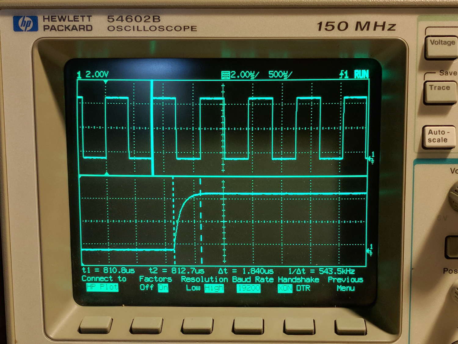
Obviously, I should code up a testcase to hammer the OLED and peer at the results on the oscilloscope: one careful observation outweighs a thousand opinions.