Having just replaced the shower faucet cartridge, the knob insert (probably from 1998, according to a label on the shower stall) could also use some improvement:

That oblong blue tint is water. The shattered sections formerly had small fingers holding the insert into the knob:
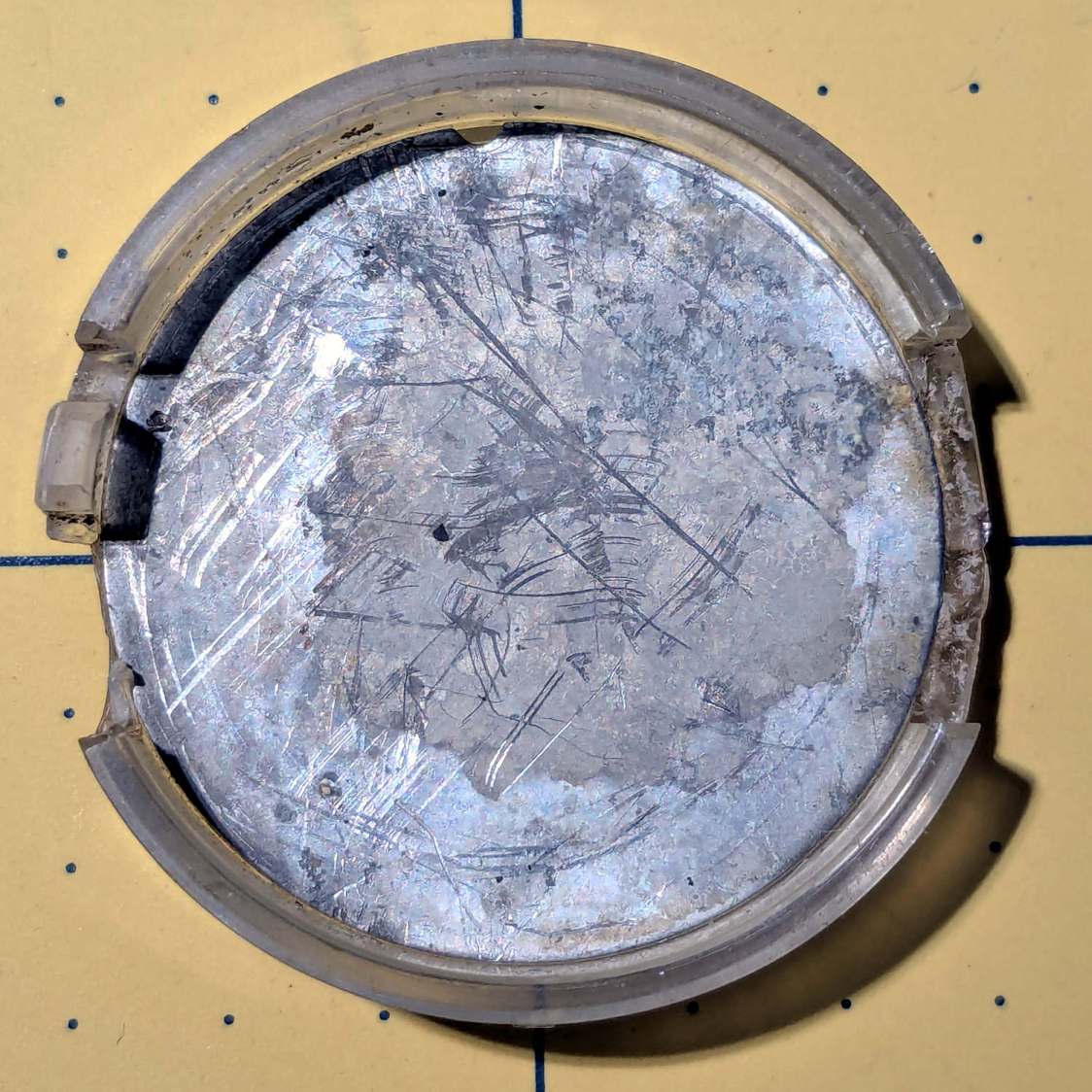
Pry the aluminum disk out of the insert and scan it:
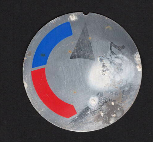
There is no feature in the knob to capture the semicircular notch at the arrow tip, so the disk can rotate as it pleases. I think the arrow should point to the OFF label on the bezel when the water is turned off, but who knows?
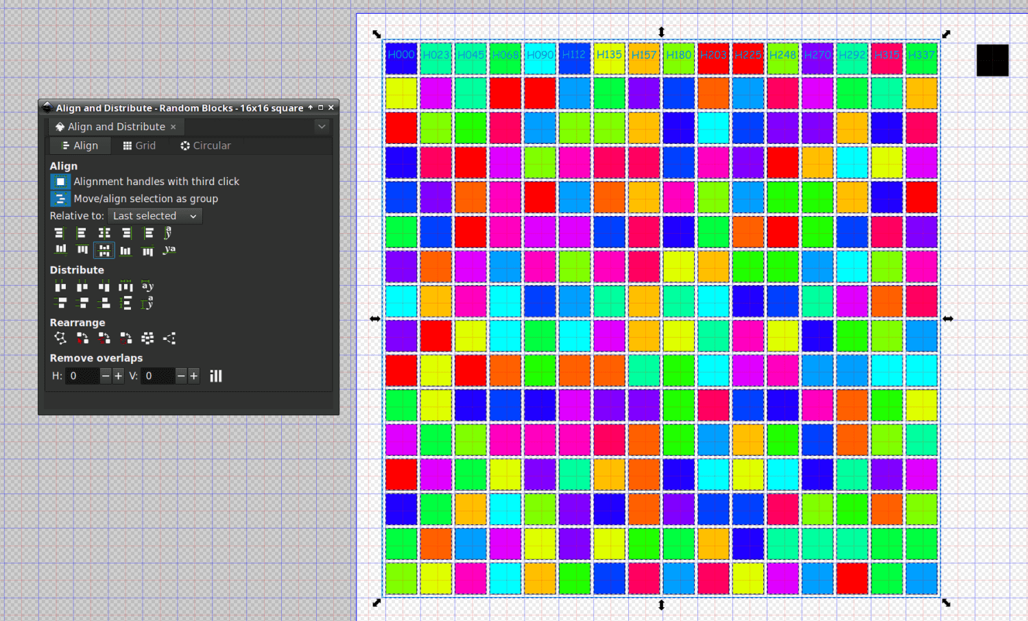
Import it into Inkscape, whereupon it becomes obvious the printed legend is not centered on the disk, lay suitable construction lines & circles, then draw similar shapes:

I located the circles at the Inkscape page corner to put their center at the (0,0) origin with the arrow pointed along the X axis to simplify importing it into OpenSCAD.
The three useful graphic features go on separate layers so OpenSCAD can treat them as separate objects:

Build the overall insert shape in OpenSCAD:
difference() {
  union() {
    tube(Insert[LENGTH],id=Insert[ID],od=Insert[OD],anchor=BOTTOM) position(TOP)
      cyl(FaceThick,d=Insert[OD],anchor=TOP);
  }
  zrot(KnobAngle)
    down(Protrusion)
      cube([2*Insert[OD],IndexWidth,Insert[LENGTH] - FaceThick + Protrusion],anchor=BOTTOM);
}
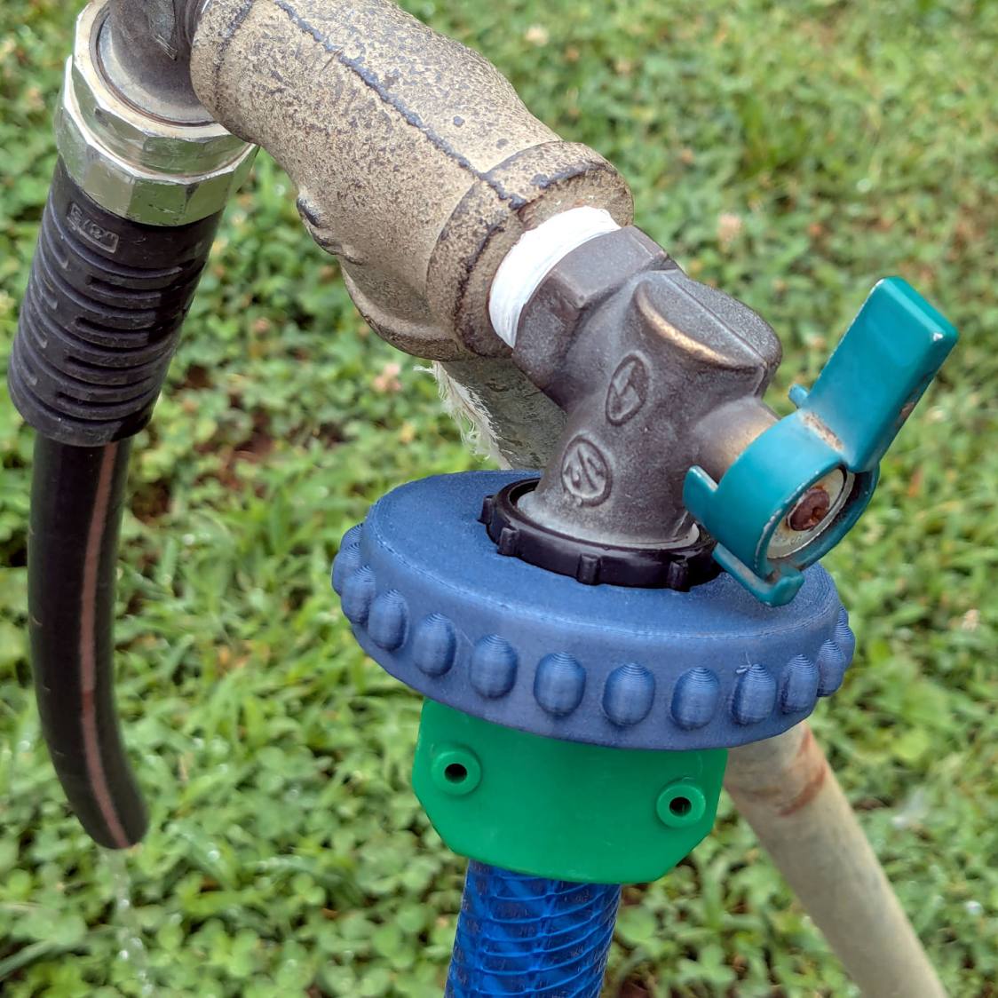
The KnobAngle rotation comes from the angle of the features inside the knob that locate the insert, which are aligned horizontally here, but at about 30° when the knob is installed on the faucet :

The knob shined up surprisingly well for being three decades old; that photo is as-found.
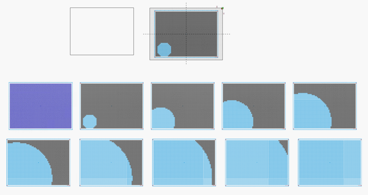
Import the Inkscape graphics into OpenSCAD and align them an itsy above the top of the insert structure to prevent Z fighting without triggering the slicer into adding another layer:
up(Insert[LENGTH] - LabelThick + 0.01)
  color("DarkSlateGray")
    linear_extrude(LabelThick)
      import(LabelFN,center=false,layer="Angle Indicator");
up(Insert[LENGTH] - LabelThick + 0.01)
  color("Red")
    linear_extrude(LabelThick)
      import(LabelFN,center=false,layer="Hot Arc");
up(Insert[LENGTH] - LabelThick + 0.01)
  color("Blue")
    linear_extrude(LabelThick)
      import(LabelFN,center=false,layer="Cold Arc");
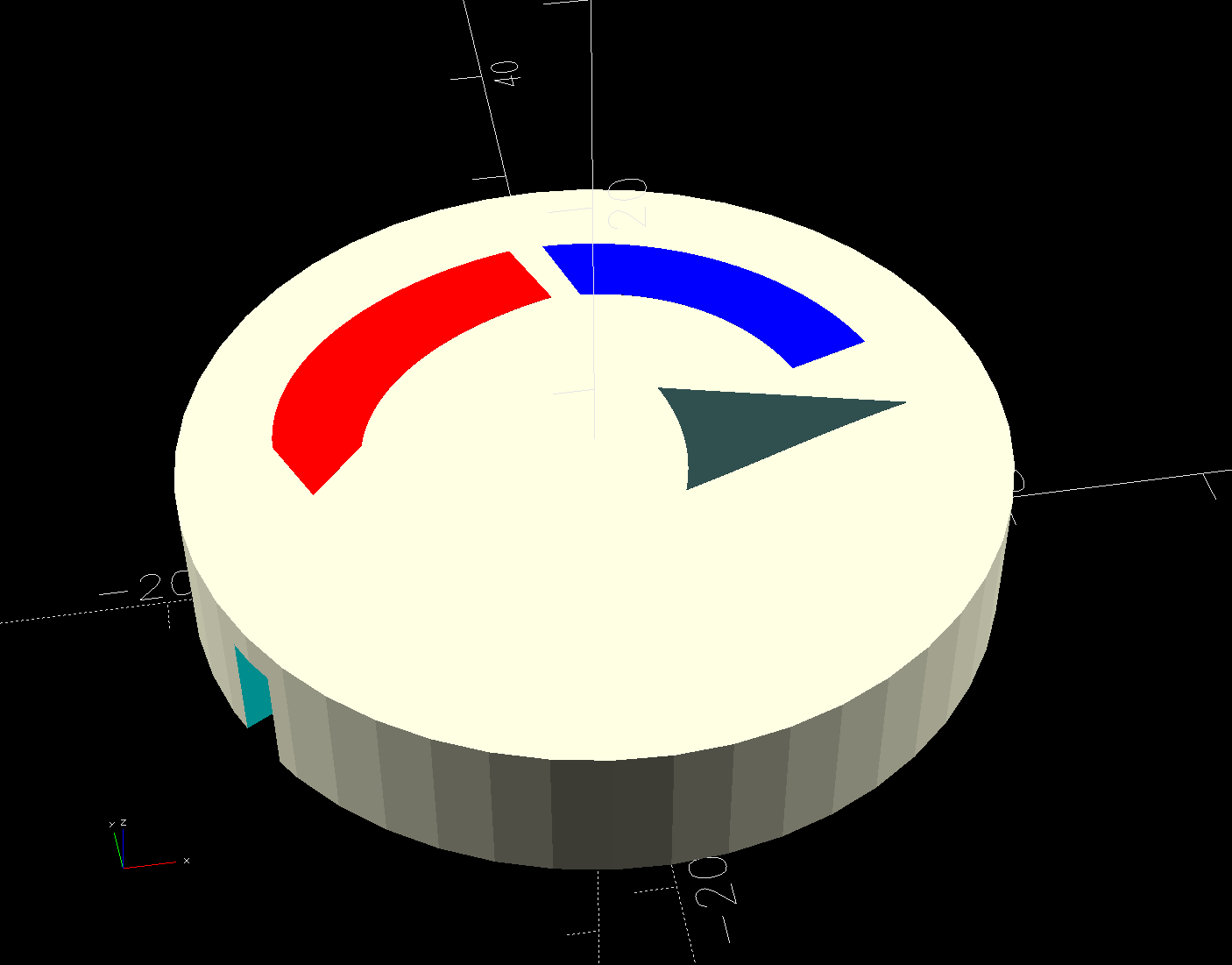
Those three shapes must be handled separately, lest OpenSCAD combine them into one thing that PrusaSlicer won’t recognize as distinct shapes. There’s no need to subtract them from the main insert shape, but getting separate colors to come out right is definitely not straightforward.
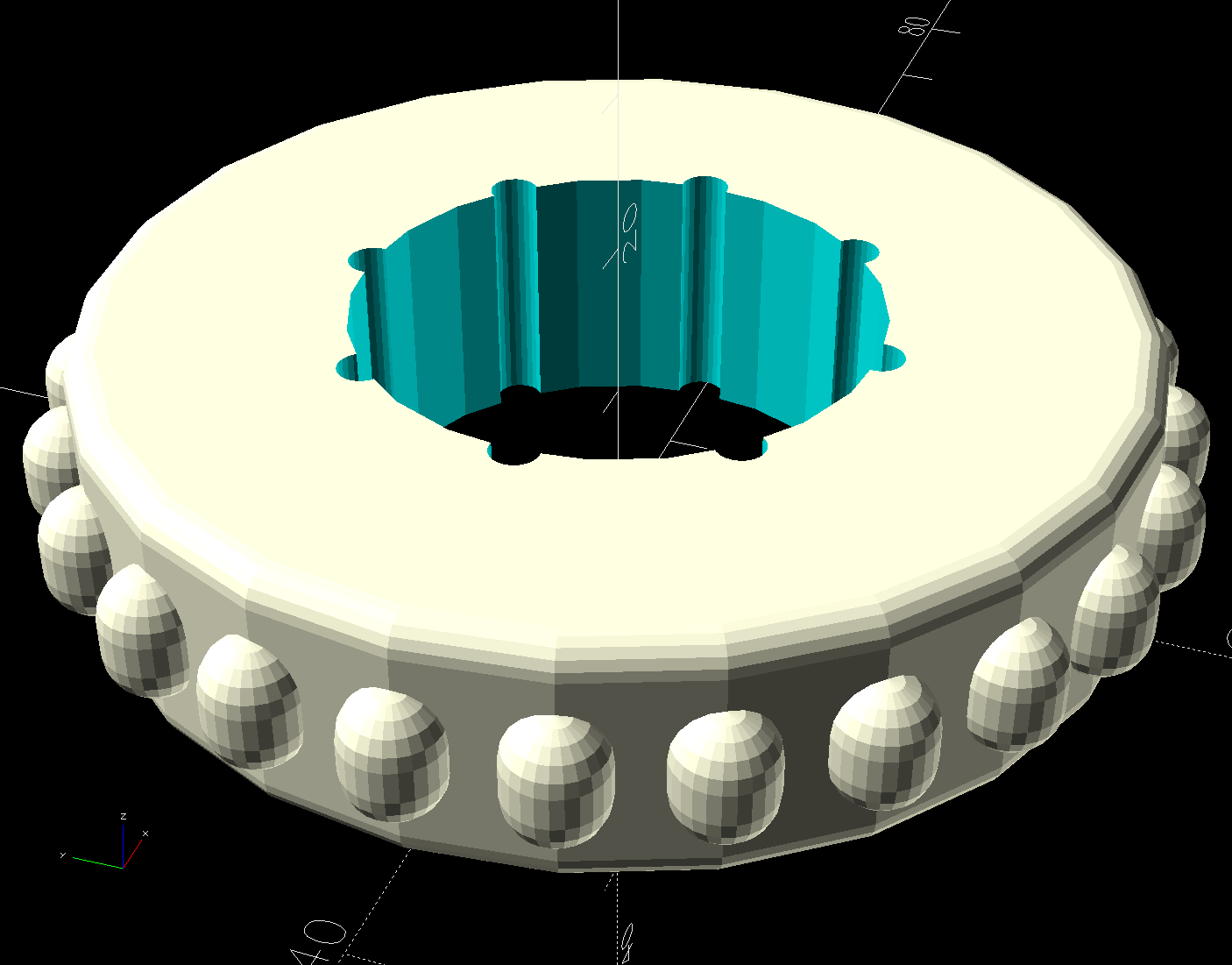
Which looks like this, with cheerful colors that need not correspond to the printer filaments:
Normally I have a set of Build transformations to orient the thing for printing, but doing a simple rotation to put the top down on the platform also blows away the separate nature of the graphics.
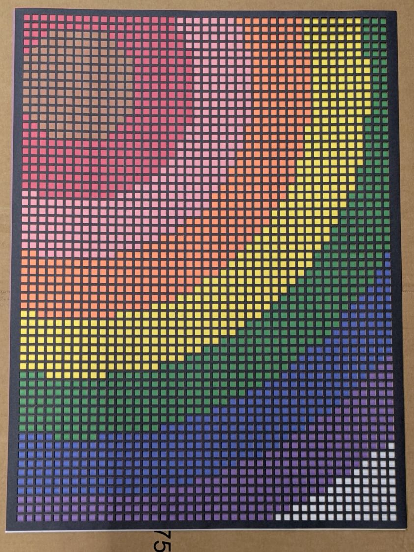
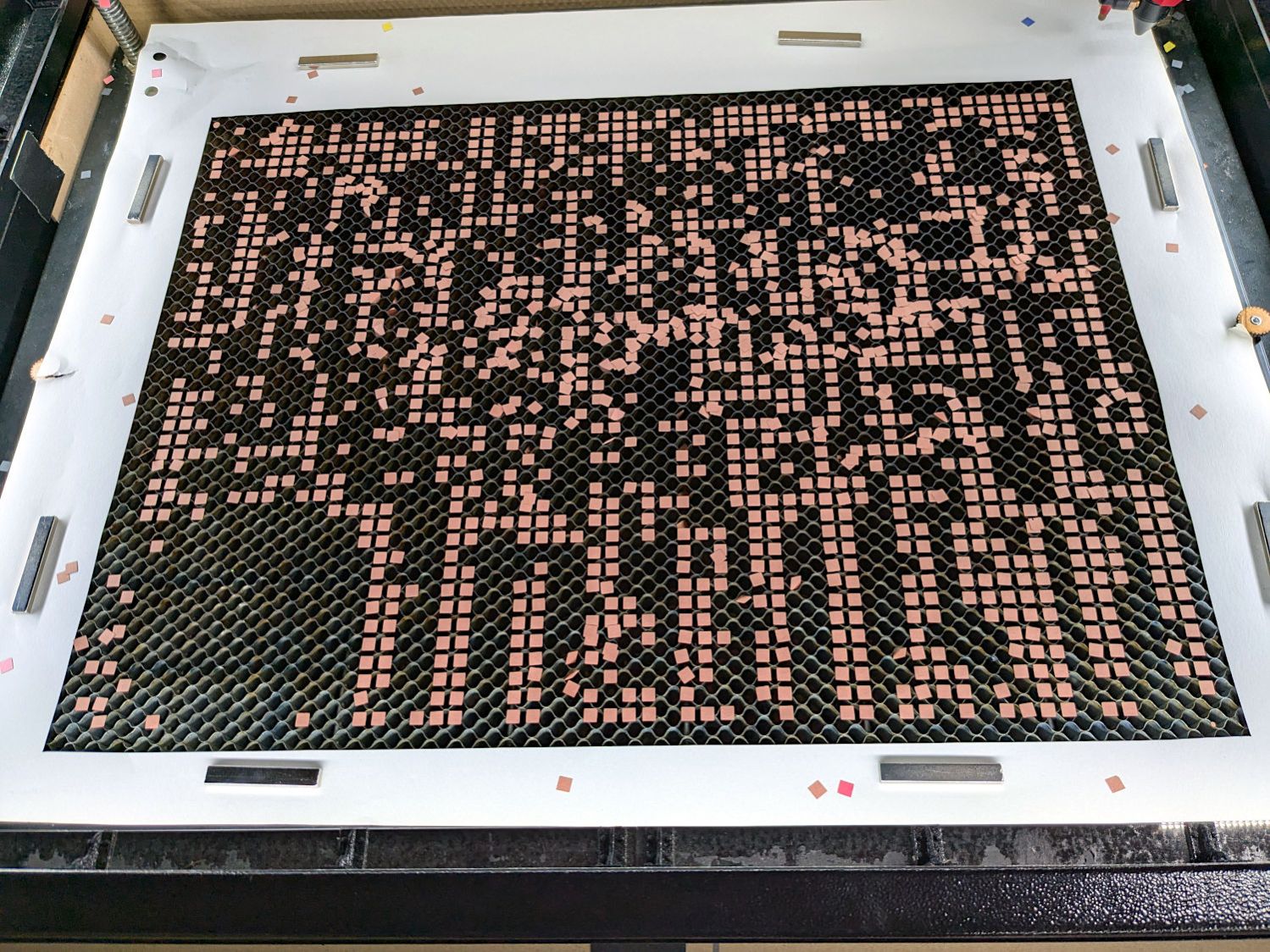
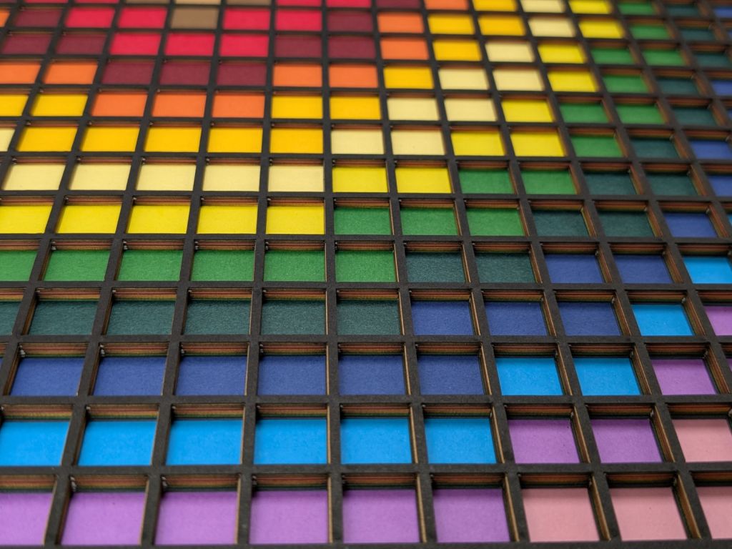
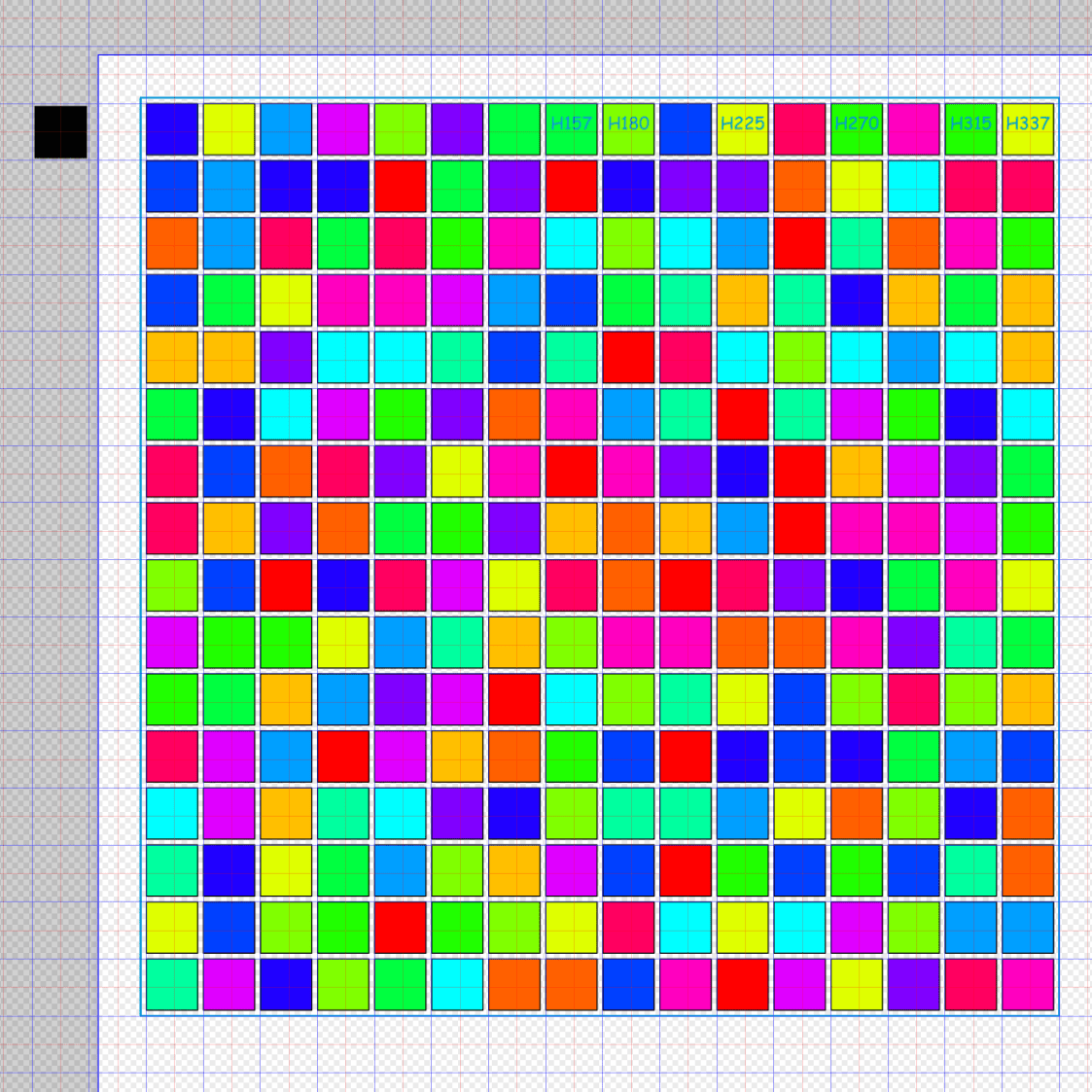
I use the EIA color code sequence in PrusaSlicer so I can identify the filament number by eye:
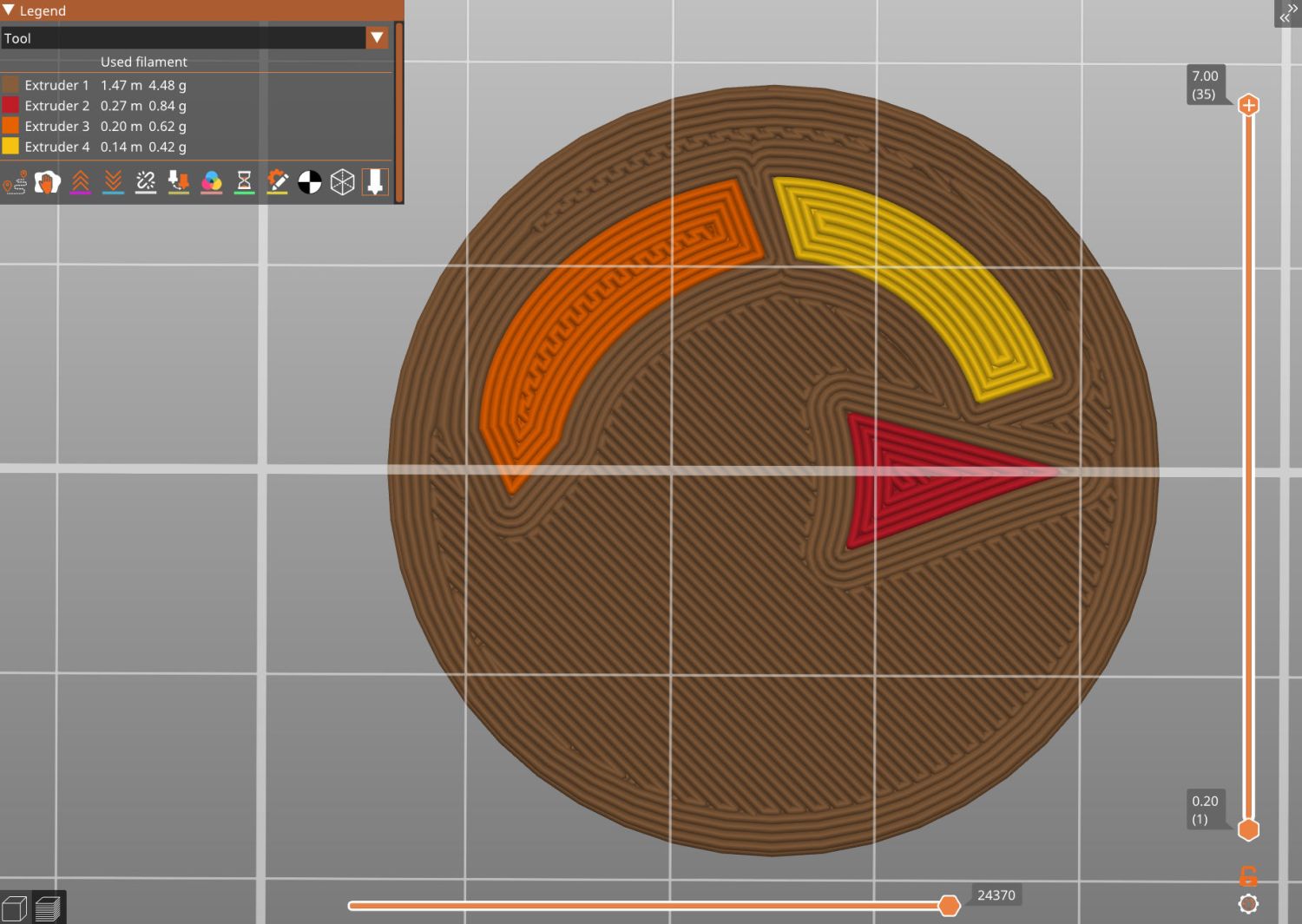
A little while later:

The insert is a loose fit in the knob, held in place by good double-sided foam tape to the screw securing the knob. I decided to not bother with little fingers, because I loves me some simple removable adhesive action.
Yeah, you can buy an entire replacement knob for ten bucks, but where’s the fun in that?
The OpenSCAD source code as a GitHub Gist:
| // Delta shower faucet knob insert | |
| // Ed Nisley – KE4ZNU | |
| // 2025-08-09 | |
| include <BOSL2/std.scad> | |
| /* [Hidden] */ | |
| HoleWindage = 0.2; | |
| Protrusion = 0.01; | |
| NumSides = 4*3*4; | |
| $fn=NumSides; | |
| ID = 0; | |
| OD = 1; | |
| LENGTH = 2; | |
| LabelFN = "Shower Fauce Knob Insert.svg"; | |
| LabelThick = 0.8; | |
| KnobAngle = 30; // horizontal to index features | |
| IndexWidth = 2.5; // slot to fit knob locating features | |
| Insert = [33.5,37.7,7.0]; // slides into knob | |
| FaceThick = 1.6; | |
| //———- | |
| // Construct it in the obvious orientation | |
| // Flip it in the slicer to preserve the artwork for separate filaments! | |
| difference() { | |
| union() { | |
| tube(Insert[LENGTH],id=Insert[ID],od=Insert[OD],anchor=BOTTOM) position(TOP) | |
| cyl(FaceThick,d=Insert[OD],anchor=TOP); | |
| } | |
| zrot(KnobAngle) | |
| down(Protrusion) | |
| cube([2*Insert[OD],IndexWidth,Insert[LENGTH] – FaceThick + Protrusion],anchor=BOTTOM); | |
| } | |
| // Must be handled separately to produce separate objects for different filaments | |
| up(Insert[LENGTH] – LabelThick + 0.01) | |
| color("DarkSlateGray") | |
| linear_extrude(LabelThick) | |
| import(LabelFN,center=false,layer="Angle Indicator"); | |
| up(Insert[LENGTH] – LabelThick + 0.01) | |
| color("Red") | |
| linear_extrude(LabelThick) | |
| import(LabelFN,center=false,layer="Hot Arc"); | |
| up(Insert[LENGTH] – LabelThick + 0.01) | |
| color("Blue") | |
| linear_extrude(LabelThick) | |
| import(LabelFN,center=false,layer="Cold Arc"); | |