The Smell of Molten Projects in the Morning

Ed Nisley's Blog: Shop notes, electronics, firmware, machinery, 3D printing, laser cuttery, and curiosities. Contents: 100% human thinking, 0% AI slop.

Category: Software

General-purpose computers doing something specific

  • Square Patio Table Feet

    Square Patio Table Feet

    For a square patio table (with one missing foot), of course:

    Patio Table Feet - installed
    Patio Table Feet – installed

    These are chunky enough to demonstrate they’re made of clear-ish TPU, at least when backlit:

    Patio Table Feet - installed - backlit
    Patio Table Feet – installed – backlit

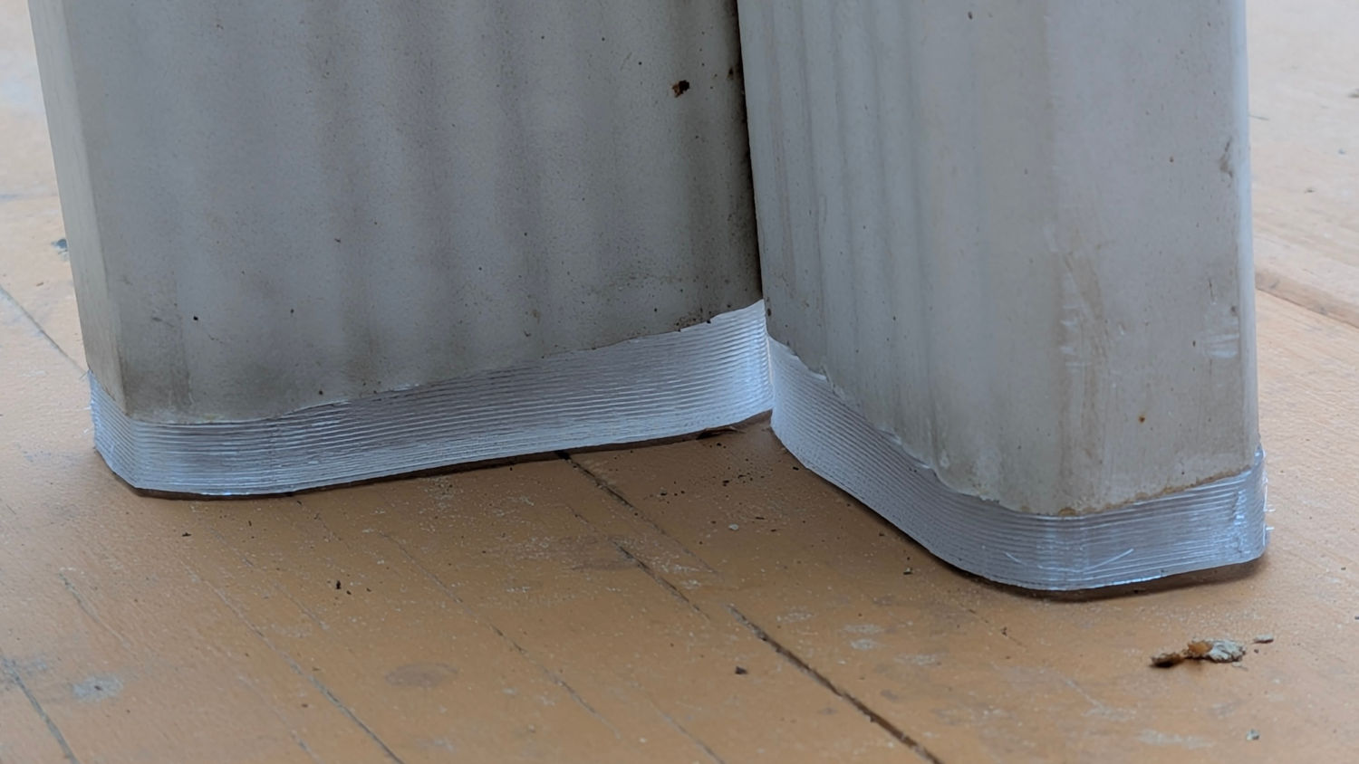
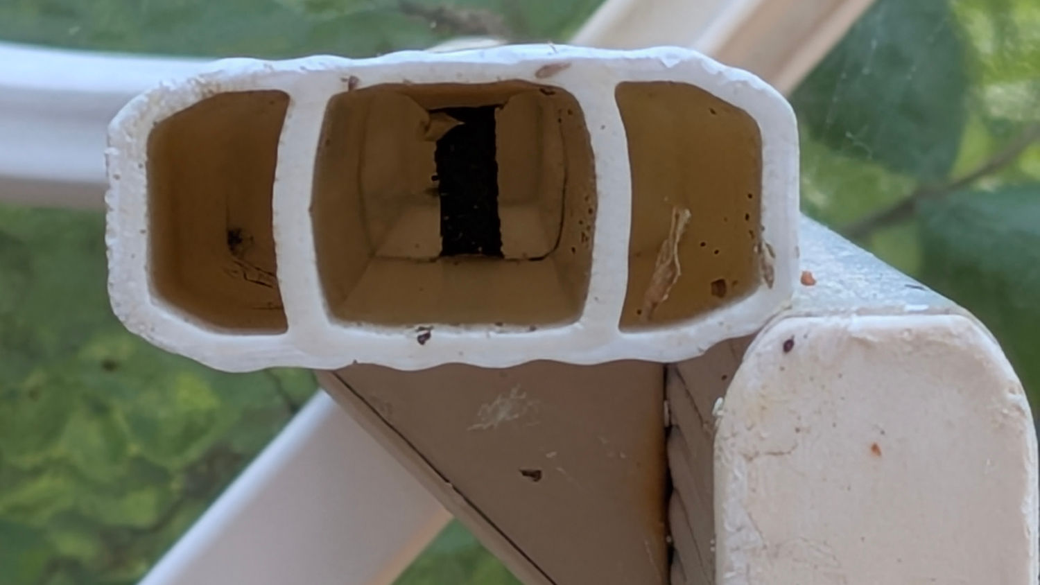
    The interior of the leg determines what fits into it:

    Patio Table Feet - leg interior
    Patio Table Feet – leg interior

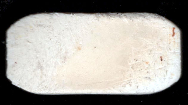
    I pried out another foot, scanned it, and blew out the contrast:

    Patio Table Foot - scan
    Patio Table Foot – scan

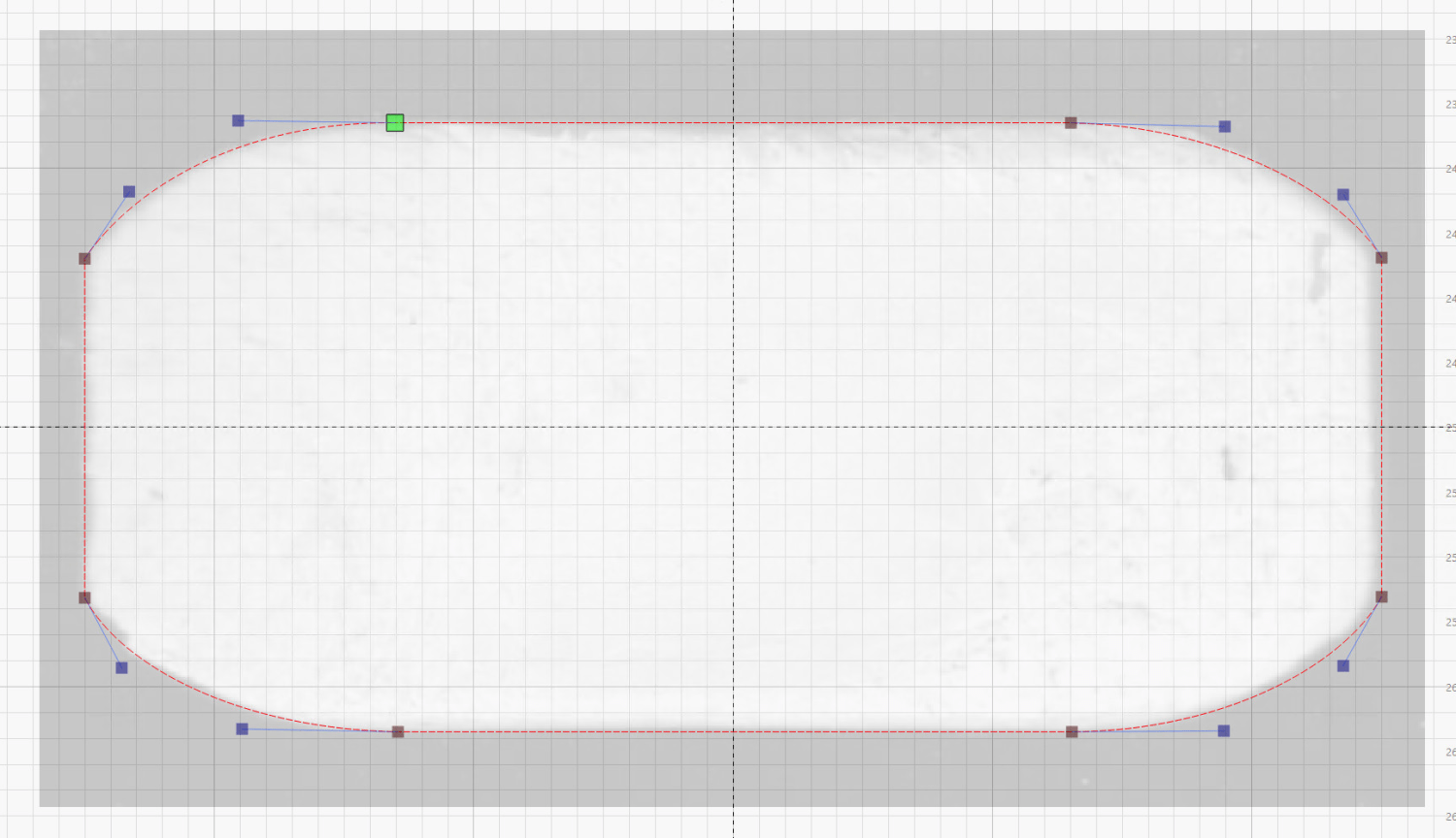
    Importing that into LightBurn let me draw a rectangle matching the measured size, then node-edit the corners to approximate the shape:

    Patio Table Foot - LightBurn layout
    Patio Table Foot – LightBurn layout

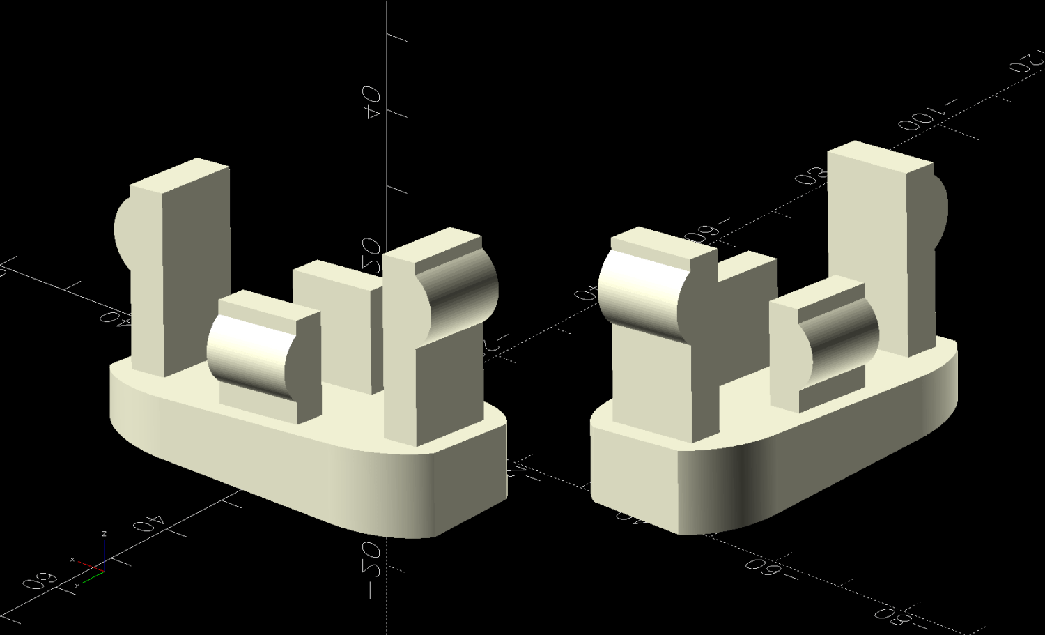
    Export that shape as an SVG, import into OpenSCAD, and turn it into a solid model:

    Patio Table Foot - solid model - show view
    Patio Table Foot – solid model – show view

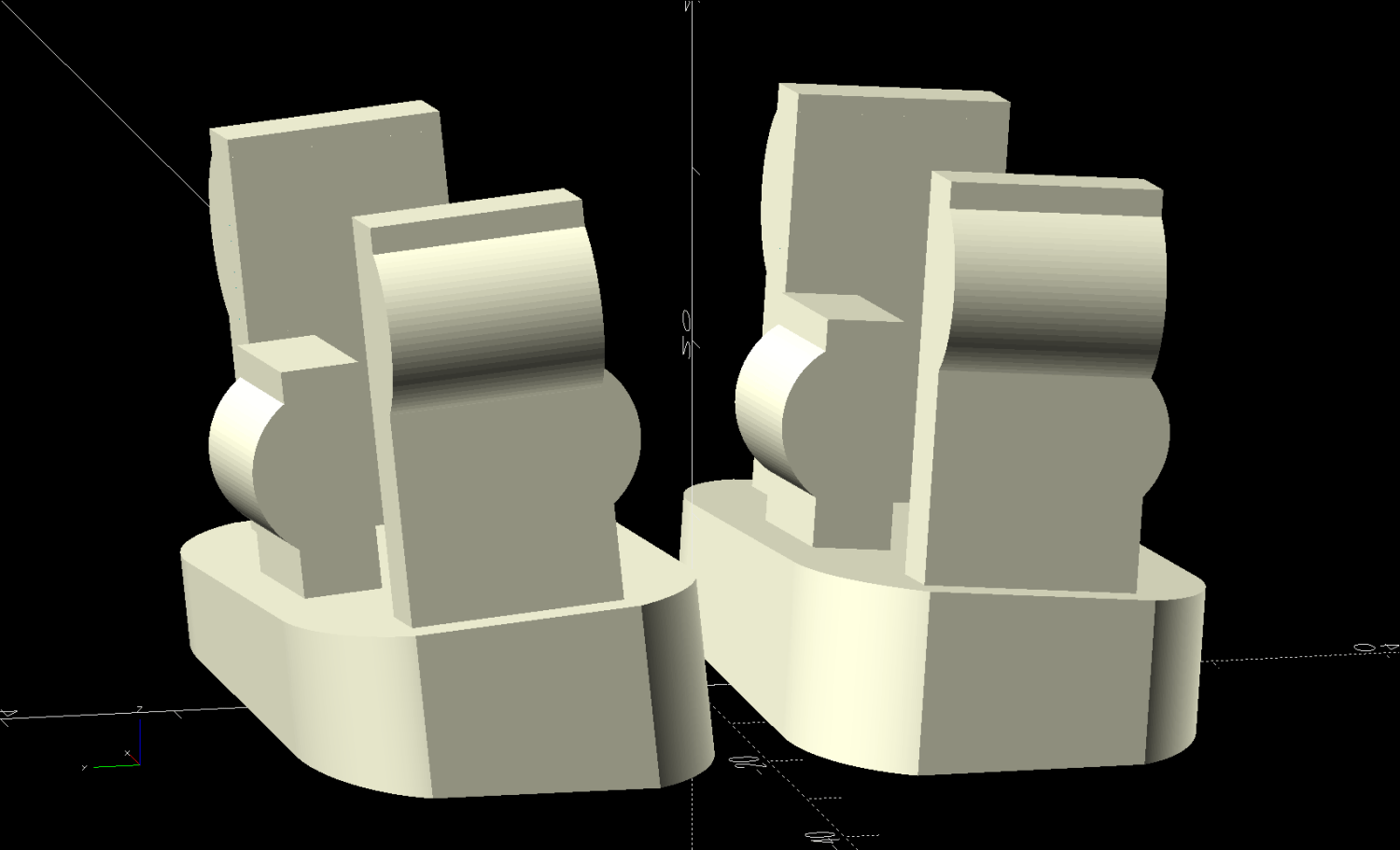
    That’s the Show view simulating the actual positions, which demonstrates why the pair of legs at each corner wear mirror-imaged feet. The Build view arranges the pair more sensibly for 3D printing:

    Patio Table Foot - solid model - build view
    Patio Table Foot – solid model – build view

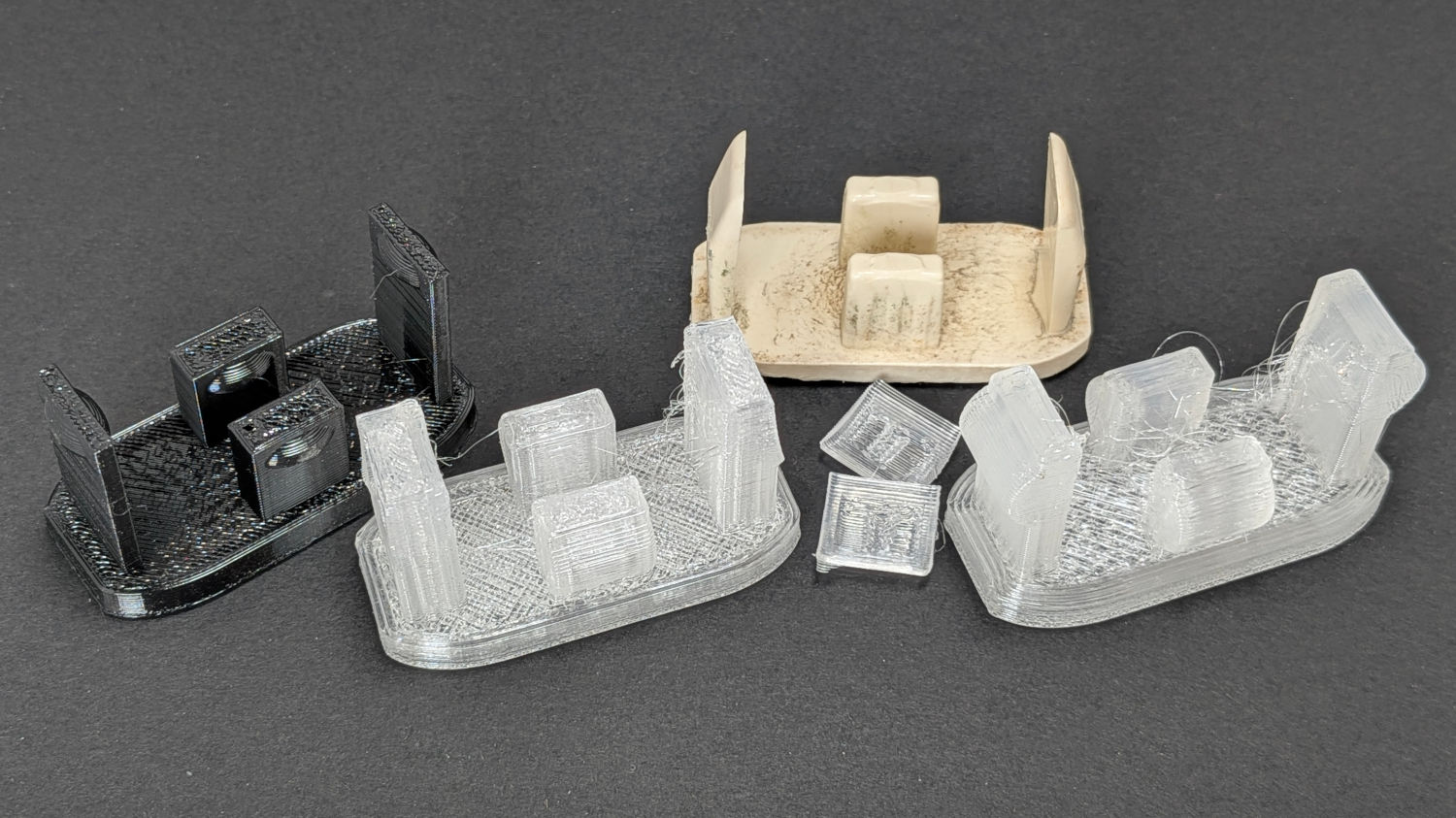
    The protrusions and their bumps went through several iterations on the way to being functional, with the black TPU prototype on the left being entirely too bendy and the first clear version requiring utility knife editing to fit the end posts inside the leg:

    Patio Table Feet - prototypes
    Patio Table Feet – prototypes

    The original feet seem to be injection-molded ABS with a flat bottom intended to erode one corner against whatever the table stands on. However, the legs splay out at 5° from the vertical, which makes the flat bottom I used for the first few iterations obviously wrong:

    Patio Table Feet - flat foot
    Patio Table Feet – flat foot

    Somebody who can math harder than I would resolve the two angles and all the measurements into a single transformation matrix, but I rotated the foot separately around the X and Y axes, trigged the lowest corner to the proper height, then chopped off everything below Z=0. Works for me.

    The OpenSCAD source code as a GitHub Gist:

    // Patio Table Foot – rectangular legs
    // Ed Nisley – KE4ZNU
    // 2026-05-26
    include <BOSL2/std.scad>
    Layout = "Show"; // [Show,Build]
    /* [Hidden] */
    HoleWindage = 0.2;
    Protrusion = 0.01;
    NumSides = 4*3*2*4;
    Gap = 5.0/2;
    $fn=NumSides;
    PadOA = [50,23.5,4.5];
    LegAngles = [5,5];
    EndStrut = [2.5 + 2.5,13.3 – 1.0,23.0];
    SideStrut = [12.0,5.5 – 1.0,13.0];
    Clearance = 0.5;
    StrutsOC = [44.0 – EndStrut.x,18.0 – SideStrut.y];
    //—–
    // Define it
    module Foot(angles = LegAngles) {
    difference() {
    up((PadOA.x/2)*abs(sin(angles.x)) + (PadOA.y/2)*abs(sin(angles.y)))
    xrot(angles.x) yrot(angles.y)
    union() {
    down(3*PadOA.z)
    linear_extrude(4*PadOA.z)
    left(PadOA.x/2) fwd(PadOA.y/2)
    import("Patio Table Foot – pad outline.svg",center=true);
    up(PadOA.z)
    for (i = [-1,1])
    right(i*StrutsOC.x/2)
    cuboid(EndStrut,anchor=BOTTOM) position(TOP)
    down(EndStrut.y/2) left(i*Clearance)
    pie_slice(r=(PadOA.x – StrutsOC.x)/2,ang=180,l=EndStrut.y,anchor=CENTER,spin=-i*90,orient=FRONT);
    up(PadOA.z)
    for (j = [-1,1])
    fwd(j*StrutsOC.y/2)
    cuboid(SideStrut,anchor=BOTTOM) position(TOP)
    down(SideStrut.x/2) zrot(90) right(j*Clearance)
    pie_slice(r=(PadOA.y – StrutsOC.y)/2,ang=180,l=SideStrut.x,anchor=CENTER,spin=j*90,orient=FRONT);
    }
    cuboid(4*PadOA,anchor=TOP);
    }
    }
    //—–
    // Build it
    if (Layout == "Show") {
    back(PadOA.y/2 + Gap)
    Foot();
    left(0.8*PadOA.x) fwd(PadOA.y) zrot(-90)
    yflip() Foot();
    }
    if (Layout == "Build") {
    union() {
    fwd(PadOA.y/2 + Gap)
    Foot();
    back(PadOA.y/2 + Gap)
    yflip() Foot();
    }
    }

  • Round Patio Table Feet

    Round Patio Table Feet

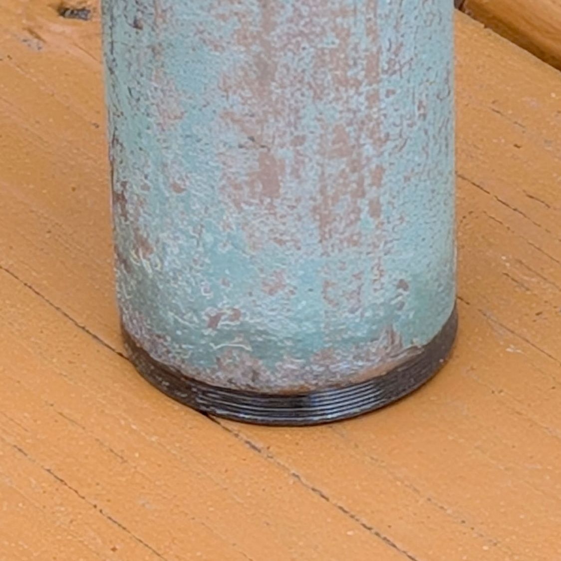
    For a round patio table, although you can’t tell from the picture:

    Round patio table feet - installed
    Round patio table feet – installed

    Also despite appearances, that’s 3D printed from clear-ish TPU, with its black appearance due to internal reflections from the leg’s dark interior.

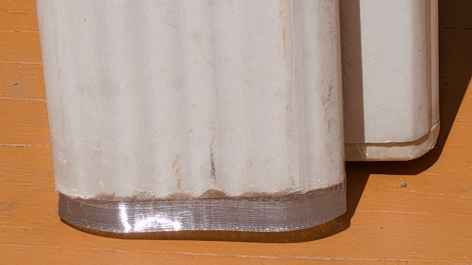
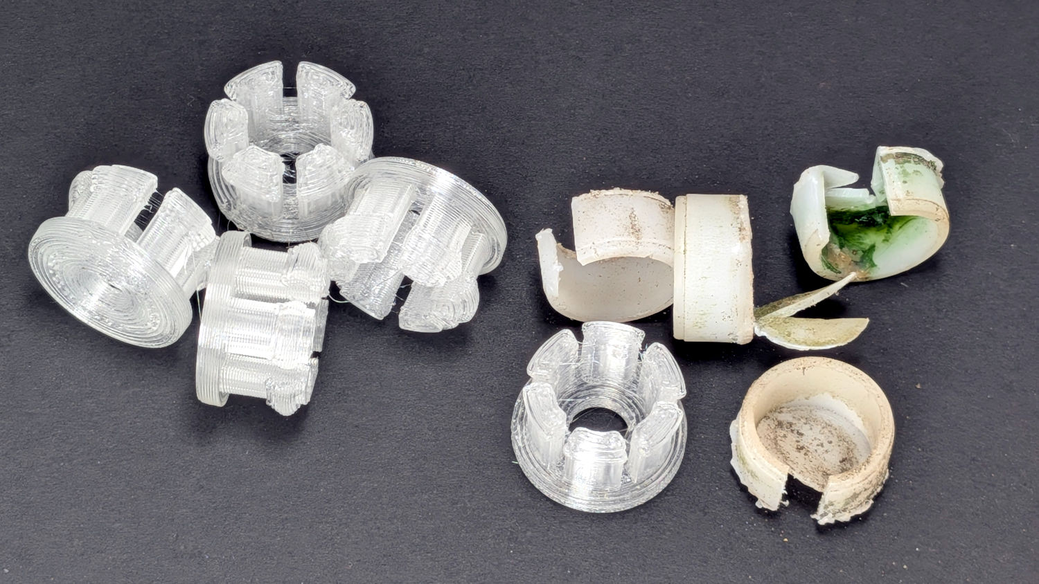
    The original hard-white-plastic feet had eroded enough to let the aluminum legs scrape the deck paint:

    Round patio table feet - old vs new
    Round patio table feet – old vs new

    The only way to extract each old foot was to hack out a segment with a razor knife, after which it slid out easily.

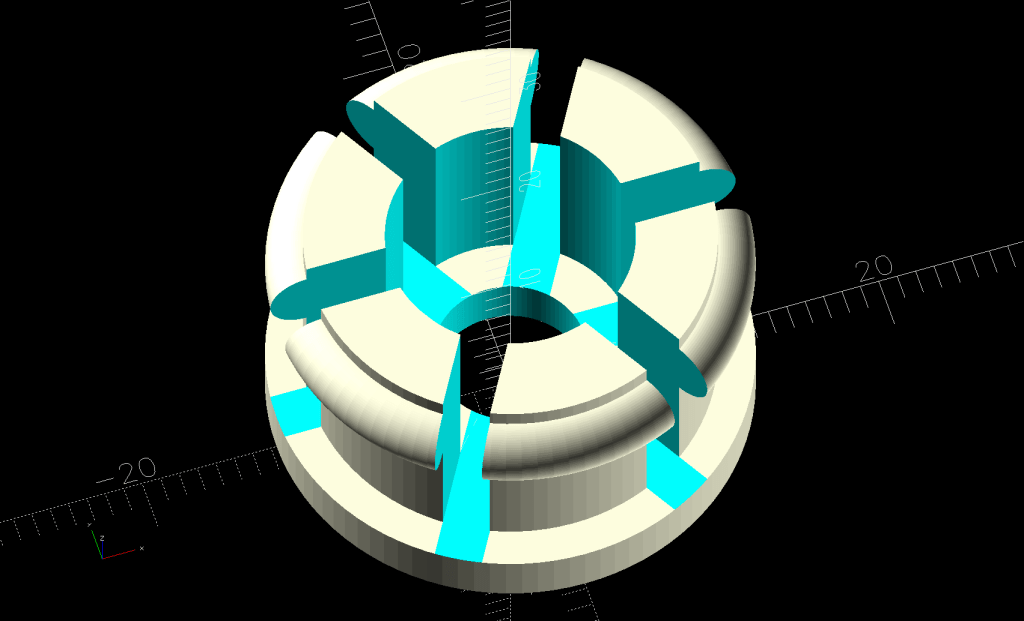
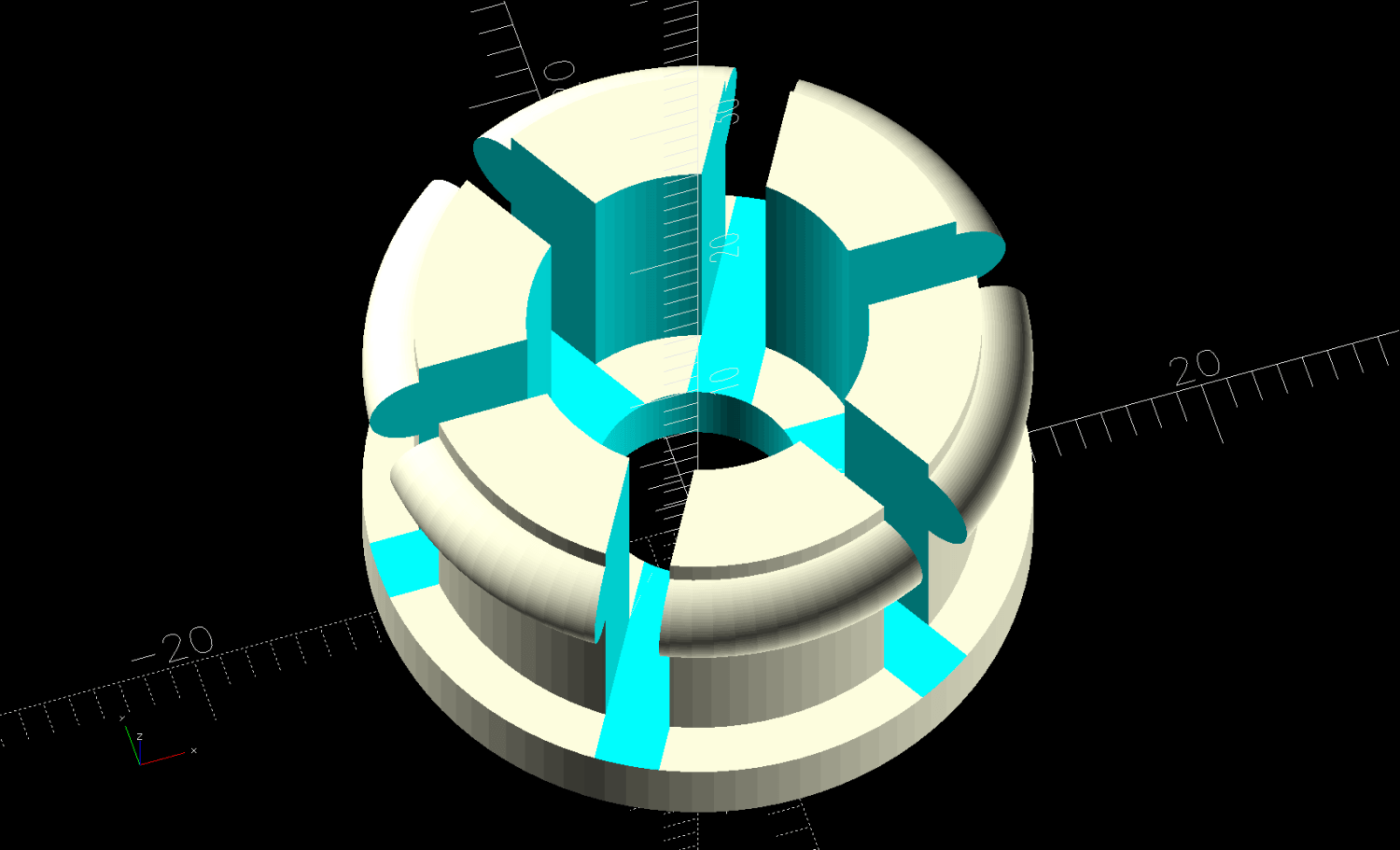
    The ring around the top of the sections provides enough griptivity inside the leg to hold the foot in place:

    Round Patio Table Foot - solid model
    Round Patio Table Foot – solid model

    As with the TPU chains on the bike rack tray holder, I expect the compressed / bent segments will gradually relax inside the legs, but the feet ought not fall out in normal use.

    The OpenSCAD source code isn’t quite a one-liner, but it’s close:

    // Patio Table Foot - round legs
    // Ed Nisley - KE4ZNU
    // 2026-05-29
    
    include <BOSL2/std.scad>
    
    /* [Hidden] */
    
    ID = 0;
    OD = 1;
    LENGTH = 2;
    
    HoleWindage = 0.2;
    Protrusion = 0.01;
    NumSides = 4*3*2*4;
    Gap = 5.0;
    
    $fn=NumSides;
    
    PadOA = [8.0,1*INCH,3.0];
    
    SleeveOA = [13.0,21.7 - HoleWindage,12.0];
    
    Kerf = 2.5;
    
    
    //-----
    // Build it
    
    difference() {
      union() {
        tube(PadOA[LENGTH],od=PadOA[OD],id=PadOA[ID],anchor=BOTTOM) position(TOP)
          tube(SleeveOA[LENGTH],od=SleeveOA[OD],id=SleeveOA[ID],anchor=BOTTOM);
        up(PadOA[LENGTH] + SleeveOA[LENGTH] - 1.0)
          torus(d_maj=SleeveOA[OD],r_min=(PadOA[OD] - SleeveOA[OD])/2,anchor=TOP);
      }
      up(PadOA[LENGTH])
        for (a = [0,60,120])
          zrot(a)
            cuboid([PadOA[OD],Kerf,2*SleeveOA[LENGTH]],anchor=BOTTOM);
    }
    
    
  • Bike Rack Tray Holder: Stretchy Tiedown Straps

    Bike Rack Tray Holder: Stretchy Tiedown Straps

    The tray holder on Mary’s bike worked well:

    Bike Rack Tray Holder - in use
    Bike Rack Tray Holder – in use

    Except for having the bungee cord run across the middle of the tray where it blocks access for larger trays and tends to bend the taller leaves.

    Well, I can fix that:

    Bike Rack Tray Holder - straps - rear
    Bike Rack Tray Holder – straps – rear

    The front tiedown is similar:

    Bike Rack Tray Holder - straps - front
    Bike Rack Tray Holder – straps – front

    They’re printed from TPU: rectangular blocks and chains, ending in wire hooks bashed from a coat hanger. The M4 button-head screws thread into (uncrushed) rivnuts, which seemed easier to manage than square nuts in this situation.

    The chains are just thick circles, with half of the top links sunk into the blocks:

    Stretchy Straps - build layout
    Stretchy Straps – build layout

    You’d (well, I’d) want to build them one at a time, because sometimes this happens:

    Bike Rack Tray Holder - bad platform adhesion
    Bike Rack Tray Holder – bad platform adhesion

    Based on those measurements, I raised the extruder by 0.1 mm, but apparently did a poor job of cleaning / flattening the cold TPU on the nozzle and got it wrong. As a result, the first layer didn’t get squooshed properly onto the BuildTak, came unstuck, and produced art . The track down the middle of the photo shows traces of a previous, badly over-squooshed test chain.

    The stretched TPU relaxes enough to leave very little tension after a day, as shown by the unhooked right chain:

    Bike Rack Tray Holder - straps - relaxing
    Bike Rack Tray Holder – straps – relaxing

    However, that make the chains exactly the right length, so they require even more force to get the hooks off the rack. After relaxing for another day, the stretched chains return to roughly their original lengths, so it’s all good.

    The OpenSCAD source code as a GitHub Gist:

    // TPU Tiedown Straps for bike rack tray holder
    // Ed Nisley – KE4ZNU
    // 2026-05-14
    include <BOSL2/std.scad>
    Layout = "Build"; // [Show,Build,Chain,Blocks,Front,Rear]
    /* [Hidden] */
    HoleWindage = 0.2;
    Protrusion = 0.01;
    NumSides = 4*3*2*4;
    Gap = 5.0;
    $fn=NumSides;
    LinkID = 7.0;
    LinkOD = 10.0;
    LinkOC = 14.0;
    LinkHeight = 4.0;
    JointWidth = 2.0;
    FrontChainAngle = 30; // from vertical
    FrontChainLength = 80.0; // nominal length
    RearChainAngle = 20; // from vertical
    RearChainLength = 100.0; // nominal length
    BlockOA = [80.0,12.0,15.0];
    InsertOC = 30.0;
    //—–
    // Define things
    module Chain(n=2) {
    render()
    difference() {
    union() {
    hull() {
    cyl(LinkHeight,d=JointWidth,anchor=BOTTOM,rounding=0.0);
    back((n – 1)*LinkOC)
    cyl(LinkHeight,d=JointWidth,anchor=BOTTOM,rounding=0.0);
    }
    for (i = [0:n-1])
    back(i*LinkOC)
    cyl(LinkHeight,d=LinkOD,anchor=BOTTOM,rounding=0.0);
    }
    for (i = [0:n-1])
    back(i*LinkOC)
    down(Protrusion)
    cyl(LinkHeight + 2*Protrusion,d=(LinkID + HoleWindage),anchor=BOTTOM,rounding=-1.0);
    }
    }
    module FrontBlock() {
    difference() {
    cuboid(BlockOA,anchor=BOTTOM,chamfer=1.0,except=BACK);
    for (i = [-1:1])
    right(i*InsertOC) down(Protrusion) {
    cyl(BlockOA.z + 2*Protrusion,d=4.0 + HoleWindage,anchor=BOTTOM); // screw clearance
    cyl(1.5,d=9.0,anchor=BOTTOM); // insert head
    cyl(11.0,d=6.0,anchor=BOTTOM); // insert body
    }
    }
    }
    module RearBlock() {
    up(BlockOA.z/2) fwd(BlockOA.y/2)
    difference() {
    cuboid(BlockOA,anchor=FRONT,chamfer=1.0,except=BACK);
    for (i = [-1:1])
    right(i*InsertOC) fwd(Protrusion) {
    ycyl(BlockOA.z + 2*Protrusion,d=4.0 + HoleWindage,anchor=FRONT); // screw clearance
    ycyl(1.5,d=9.0,anchor=FRONT); // insert head
    ycyl(11.0,d=6.0,anchor=FRONT); // insert body
    }
    }
    }
    module FrontAssembly(cl=FrontChainLength,ca=FrontChainAngle) {
    Links = ceil(cl / LinkOC);
    union() {
    up(cl*cos(ca)) {
    FrontBlock();
    back(BlockOA.y/2)
    xrot(90)
    for (i = [-1,1])
    left(i*InsertOC/2)
    zrot(-i*ca + 180)
    Chain(Links);
    }
    }
    }
    module RearAssembly(cl=RearChainLength,ca=RearChainAngle) {
    Links = ceil(cl / LinkOC);
    union() {
    up(cl*cos(ca)) {
    RearBlock();
    back(BlockOA.y/2)
    xrot(90)
    for (i = [-1,1])
    left(i*InsertOC/2)
    zrot(-i*ca + 180)
    Chain(Links);
    }
    }
    }
    //—–
    // Build things
    if (Layout == "Chain")
    Chain();
    if (Layout == "Blocks") {
    fwd(BlockOA.y)
    FrontBlock();
    back(BlockOA.y)
    RearBlock();
    }
    if (Layout == "Front")
    FrontAssembly();
    if (Layout == "Rear")
    RearAssembly();
    if (Layout == "Show") {
    fwd(BlockOA.y)
    FrontAssembly();
    back(BlockOA.y)
    zrot(180)
    RearAssembly();
    }
    if (Layout == "Build") {
    fwd(BlockOA.z + Gap/2)
    up(BlockOA.y/2)
    xrot(-90)
    down(FrontChainLength*cos(FrontChainAngle))
    FrontAssembly();
    back(BlockOA.z + Gap/2)
    zrot(180)
    up(BlockOA.y/2)
    xrot(-90)
    down(RearChainLength*cos(RearChainAngle))
    RearAssembly();
    }
  • Prusa MK4: Camera Mount Bird’s Nest

    Prusa MK4: Camera Mount Bird’s Nest

    Having just set up the camera to watch the Prusa MK4’s platform, this situation caught my eye while sitting in the Comfy Chair at my desk:

    Prusa MK4 - Bird Nest - A
    Prusa MK4 – Bird Nest – A

    (The camera in the lower right doesn’t yet record videos, so you must imagine what I saw.) I forgot capturing this screenshot:

    Prusa MK4 - Bird Nest - platform camera
    Prusa MK4 – Bird Nest – platform camera

    The nozzle was busily adding to the tangle, so I shut the printer off and trotted to the Basement Shop™ to find two more parts lying dead on the workbench:

    Prusa MK4 - Bird Nest - B
    Prusa MK4 – Bird Nest – B

    This was entirely my fault, as I’d ignored PrusaSlicer’s warning about inadequate adhesion for the camera mount link standing in the corner:

    Prusa MK4 - Camera Mount Links - slicer preview
    Prusa MK4 – Camera Mount Links – slicer preview

    That’s the PrusaSlicer preview after adding a wider brim and painting more support structures on all three parts. Given larger footprints, the next attempt completed without drama, which is the normal outcome.

    Moral of the story: Tall skinny parts need more surface area on the platform than you think, even with excellent adhesion.

  • RPi Camera RTSP Setup

    RPi Camera RTSP Setup

    The rpicam.cfg file holding the parameters for the Raspberry Pi watching the Prusa MK 4 printer:

    bitrate=2000000 
    framerate=15
    timeout=0 
    nopreview= 
    codec=libav 
    libav-format=mpegts 
    width=1280
    height=720
    rotation=180
    roi=0.00,0.00,1.0,1.0
    hdr=auto
    

    The RPi camera for the wren nest is just taped to the window, but has a configuration providing a bigger picture:

    bitrate=2000000 
    framerate=15
    timeout=0 
    nopreview= 
    codec=libav 
    libav-format=mpegts 
    width=1920 
    height=1080 
    roi=0.00,0.00,1.0,1.0
    hdr=auto


    The useful pieces:

    • bitrate sets the average data rate, which may be too high for comfort outside your immediate LAN
    • framerate need not be as high as you think
    • nopreview prevents a preview picture while starting
    • width and height do the obvious thing, but don’t try to be too clever
    • roi picks the image from a specific part of the camera sensor, so you can adjust the image layout if you have a rigidly fixed camera
    • hdr doesn’t do anything for cheap RPi cameras

    Putting all the fiddly config in a file reduces the command line invocation to a mere jawbreaker:

    rpicam-vid --config rpicam.cfg -o - | cvlc stream:///dev/stdin --sout '#rtp{sdp=rtsp://:5886/wrens}' &
    

    Although you’d want to set that up to run automagically when the RPi starts up, for now I just fire it off as needed through an SSH session, with the ampersand letting it run after that terminal session closes.

    The RTSP port (5886) and stream (wrens) can be anything you like, which comes in handy when squirting streams through port-forwarded firewall pinholes using a router that cannot handle different external and internal port numbers.

    Useful background info:

  • Window Mount for Bamboo Bee Tunnel Nests

    Window Mount for Bamboo Bee Tunnel Nests

    Mary suggested converting wild bamboo up the hill into tunnel nests (per a xerces.org paper) for native bees buzzing around flowers in the yard, so:

    Bee Tunnel Nest - downspout installation
    Bee Tunnel Nest – downspout installation

    I hung bundles of larger tubes in trees out back, in hopes of attracting huge carpenter bees.

    3D printed mounts hold smaller bundles on the windows to let us keep an eye on the proceedings:

    Bee Tunnel Nest Mount - installed-]
    Bee Tunnel Nest Mount – installed

    Which look better when not seen though two layers of glass in desperate need of Spring Cleaning:

    Bee Tunnel Nest Mounts
    Bee Tunnel Nest Mounts

    The tabs provide a bit of pressure to hold the mounts in place, although I don’t know if they have enough springiness or will survive contact with the elements:

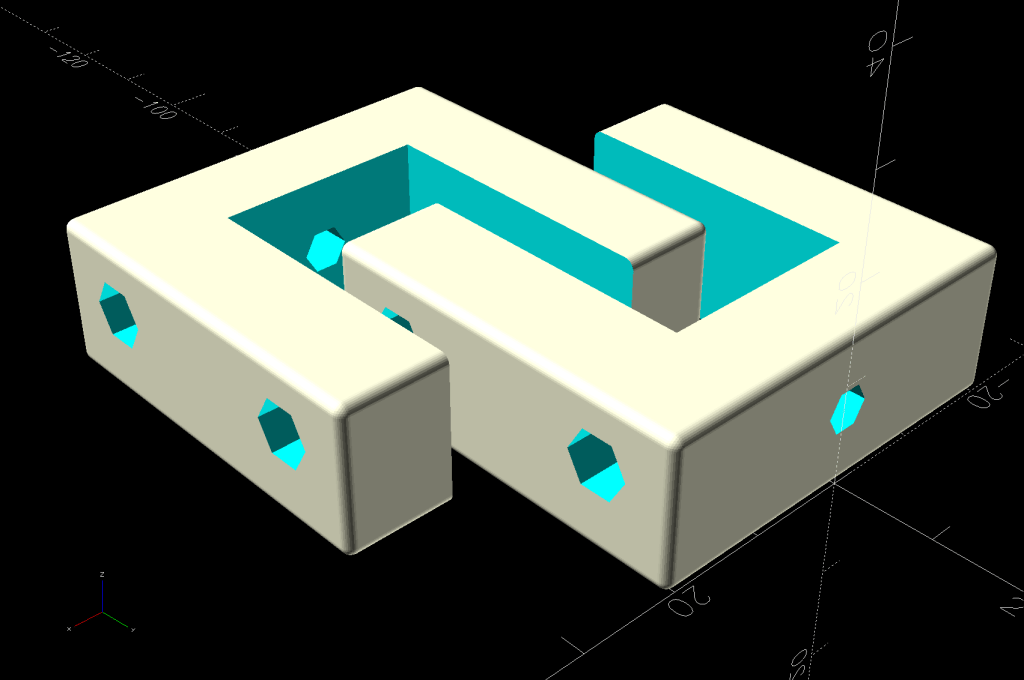
    Bee Tunnel Nest Mount - tab section - solid model
    Bee Tunnel Nest Mount – tab section – solid model

    The key advantage of not building bigger bee motels: these little bundles don’t need annual cleaning / maintenance and will eventually fall apart.

    If the bees find them suitable, more power to ’em!

    And I realized the cut-off ends fit in the rotary. Witticisms engraved on bamboo could become the New Hotness:

    Laser engraved bamboo
    Laser engraved bamboo

    Stipulated: I’m barely half-right about being a wit …

    The OpenSCAD source code as a GitHub Gist:

    // Bee Tunnel Nest Mount
    // Ed Nisley – KE4ZNU
    // 2026-04-26
    include <BOSL2/std.scad>
    Layout = "Show"; // [Build,Show,Window,Bundle,Tabs]
    BundleOD = 35.0;
    BundleOffset = 0.0;
    SlotDepth = 18.0;
    SlotGap = 1.2;
    /* [Hidden] */
    HoleWindage = 0.2;
    Protrusion = 0.01;
    NumSides = 3*2*4;
    Clearance = 0.3;
    //$fn=NumSides;
    WallThick = 2.0;
    MountHeight = 1.5*BundleOD;
    MountWidth = 1.5*BundleOD + BundleOffset;
    ClipOA = [SlotDepth + WallThick,SlotGap + 2*WallThick,MountHeight];
    BundleCtr = [-WallThick/2,ClipOA.y + MountWidth/2 + BundleOffset/2,MountHeight/2];
    TabOA = [0.7*SlotDepth,5.0,0.7*WallThick];
    TabOffset = 0.2*SlotDepth;
    TabOC = MountHeight/2;
    TabClearance = [4*Clearance,0,Clearance];
    //—–
    // Define things
    module BundleMount() {
    difference() {
    cuboid([WallThick,MountWidth + ClipOA.y,MountHeight],
    rounding=3.0,edges=[TOP+BACK,BOTTOM+BACK],anchor=FRONT+RIGHT);
    back(BundleCtr.y)
    xcyl(3*WallThick,d=BundleOD);
    for (j=[-1,1],k=[-1,1])
    translate([BundleCtr.x,j*BundleOD/2 + BundleCtr.y,k*BundleOD/2])
    xcyl(3*WallThick,d=3.0,$fn=6);
    }
    }
    module WindowMount() {
    difference() {
    cuboid(ClipOA,rounding=3.0,edges=[TOP+LEFT,BOTTOM+LEFT],
    anchor=FRONT+RIGHT);
    left(WallThick) back(WallThick)
    cuboid([2*SlotDepth,SlotGap,2*MountHeight],anchor=FRONT+RIGHT);
    for (k=[-1,1])
    translate([-(ClipOA.x – TabOffset),-Protrusion,k*TabOC/2])
    cuboid([TabOA.x + TabClearance.x,WallThick + 2*Protrusion,TabOA.y + 2*TabClearance.z],anchor=FRONT+LEFT);
    }
    }
    module Tabs() {
    for (j=[-1,1])
    fwd(j*TabOC/2)
    cuboid(TabOA,anchor=BOTTOM+LEFT) position(LEFT+TOP)
    prismoid(size1=[3*SlotGap,TabOA.y],size2=[0,TabOA.y/2],
    h=(WallThick – TabOA.z) + SlotGap/3,anchor=BOTTOM+LEFT);
    }
    module Assembly() {
    union() {
    BundleMount();
    WindowMount();
    left(ClipOA.x – TabOffset – TabClearance.x)
    xrot(-90)
    Tabs();
    }
    }
    //—–
    // Build things
    if (Layout == "Bundle") {
    BundleMount();
    }
    if (Layout == "Window") {
    WindowMount();
    }
    if (Layout == "Tabs") {
    Tabs();
    }
    if (Layout == "Show") {
    Assembly();
    }
    if (Layout == "Build") {
    yrot(90)
    Assembly();
    }
  • Steel Shelving Foot Pads

    Steel Shelving Foot Pads

    All of the plastic pads vanished from the legs of a steel shelf unit somewhere along the way:

    Steel Shelving Foot Pads - post shape
    Steel Shelving Foot Pads – post shape

    Some solid modeling produced a suitable replacement shape:

    Steel Shelving Foot Pads - no pegs - solid model
    Steel Shelving Foot Pads – no pegs – solid model

    A few prototypes (with a broken OEM version at lower left) matched the model to reality:

    Steel Shelving Foot Pads - test pieces
    Steel Shelving Foot Pads – test pieces

    They’re natural & black TPU, because the job requirements include being tough and bendy:

    Steel Shelving Foot Pads - installed
    Steel Shelving Foot Pads – installed

    Each one takes about half an hour to ooze from the Makergear M2, so after verifying the prototype’s fit, printing four at a time makes sense:

    Steel Shelving Foot Pads - slicer
    Steel Shelving Foot Pads – slicer

    The OpenSCAD code includes the pegs in the original and the first chunky TPU version:

    Steel Shelving Foot Pads - with pegs - solid model
    Steel Shelving Foot Pads – with pegs – solid model

    It turns out they don’t have any obvious benefit in a TPU pad, so they’re disabled in the code.

    Now those legs sit firmly on the floor and the post tops aren’t nearly so threatening.

    The OpenSCAD source code as a GitHub Gist:

    // Steel Shelf Foot Pads
    // Ed Nisley – KE4ZNU
    // 2026-04-18
    include <BOSL2/std.scad>
    /* [Hidden] */
    Protrusion = 0.01;
    NumSides = 4*9;
    $fn=NumSides;
    Clearance = 1.0/2;
    WallThick = 1.0 + Clearance;
    BaseThick = 2.0;
    PadOAH = BaseThick + 11.0;
    RollID = 6.4;
    RollOD = 7.4 + Clearance;
    RollOffset = 29.5;
    LegThick = 0.5 + 2*Clearance;
    Pins = [
    [-(RollOD/2), (RollOffset + RollOD/2),0],
    [(RollOffset + RollOD/2), -(RollOD/2),0],
    ];
    //—–
    // Build things
    union() {
    difference() {
    union() {
    for (pin = Pins)
    translate(pin)
    cyl(PadOAH,d=RollOD + 2*WallThick,anchor=BOTTOM);
    translate([-(WallThick + LegThick),-(WallThick + LegThick),0])
    cuboid([2*WallThick + LegThick,WallThick + LegThick + Pins[0].y,PadOAH],
    anchor=BOTTOM+LEFT+FRONT);
    translate([-(WallThick + LegThick),-(WallThick + LegThick),0])
    cuboid([WallThick + LegThick + Pins[1].x,2*WallThick + LegThick,PadOAH],
    anchor=BOTTOM+LEFT+FRONT);
    cyl(PadOAH,r=(WallThick + LegThick),anchor=BOTTOM);
    }
    up(BaseThick)
    cyl(PadOAH,r=LegThick,anchor=BOTTOM);
    up(BaseThick)
    for (pin = Pins)
    translate(pin)
    cyl(PadOAH,d=RollOD,anchor=BOTTOM);
    up(BaseThick) {
    translate(Pins[0])
    cuboid([RollOD/2,RollOD/2,PadOAH],anchor=BOTTOM+LEFT+BACK);
    translate(Pins[1])
    cuboid([RollOD/2,RollOD/2,PadOAH],anchor=BOTTOM+RIGHT+FRONT);
    }
    up(BaseThick) {
    fwd(LegThick)
    cuboid([LegThick,Pins[0].y + LegThick,PadOAH],anchor=BOTTOM+RIGHT+FRONT);
    left(LegThick)
    cuboid([Pins[1].x + LegThick,LegThick,PadOAH],anchor=BOTTOM+LEFT+BACK);
    }
    }
    if (false)
    for (pin = Pins)
    translate(pin) {
    cyl(PadOAH,d=RollID/2,anchor=BOTTOM);
    for (a = [0,90])
    zrot(a)
    cuboid([1.0,RollID – 2*Clearance,PadOAH],anchor=BOTTOM);
    }
    }