
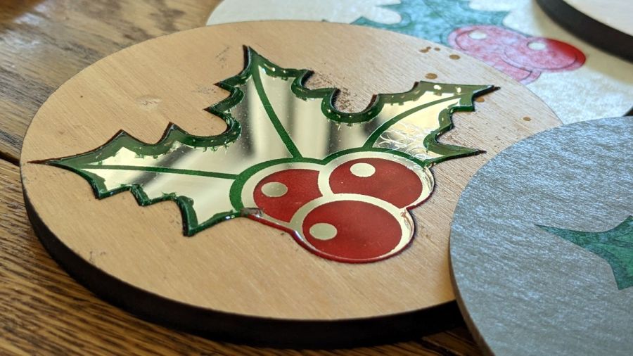
The rattlecan chipboard coasters having passed their Best Used By dates, I figured a more durable seasonal version was in order:

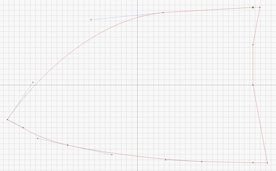
I laid out the design with the intent of cutting an acrylic snowflake with a bit of compensation to fit snugly into a plywood background:

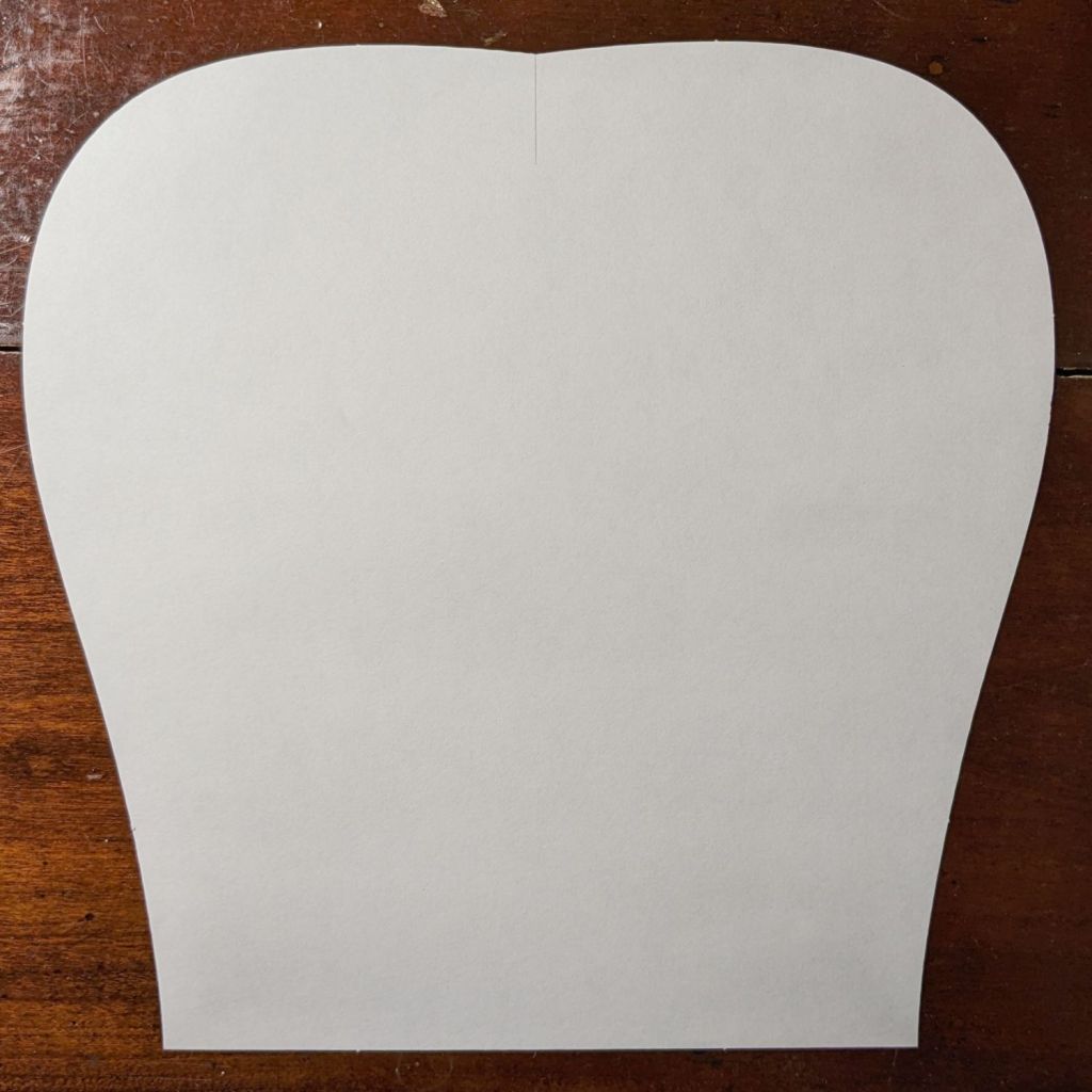
At the last moment I realized I could just cut two of the patterns on the left, swap the snowflakes, and get two coasters with very little scrap:
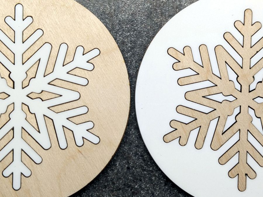
Mary thinks the gap between the snowflake and the background looks OK. I’m not convinced, but studying the results suggests applying enough kerf compensation to close the largest gaps would results in the rest of the flake not fitting into its socket. Plus, of course, you’d have more scrap.
Embiggening the small dagger-shaped pieces around the center would be an improvement. Perhaps cutting those as a separate operation after arranging them in a corner would work.
Protip: Align the grain in those daggers with the rest of the plywood, because It Will Be Very Obvious if you don’t.
Applying a nice wood stain / finish to the plywood, perhaps before cutting it out, would certainly improve the result.
Invisible on the bottom: self-adhesive cork disks eliminating the need to glue the pieces to something else. I had thought of a blank plywood or MDF disk, but came to my senses just in time.
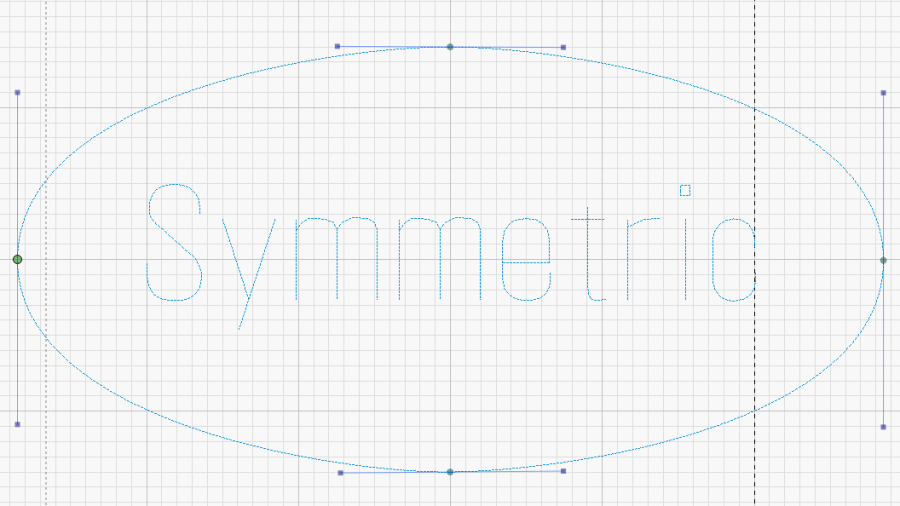
The original SVG fell with a blizzard from one of the many SVG snowflake generators out there. Because LightBurn uses only the stroke centerlines of SVG images and ignores the stroke width, it required some tweakage before becoming a coaster.
After saving an SVG flake from the blizzard, fire up Inkscape:
- Import the SVG file
- Center it in whatever page you’re using
- Ungroup the flake from the frame (if it has one)
- Delete the frame to leave only the flake
- Select the flake
- Invoke
Path → Stroke to Path - Save as an SVG image under a new file name
Then fire up LightBurn:
- Import the tweaked SVG file
- Assign a layer with line (rather than fill) parameters
- Ungroup to separate the flake’s strokes
- Weld the strokes together to remove the overlaps
- Wrap a coaster outline around it
- Resize the flake as needed
- Set layer parameters as needed
- Duplicate the flake
- Embiggen as needed
- Unleash the laser!
The LightBurn SVG layout as a GitHub Gist:


