After going through the LightBurn camera alignment / calibration process, I thought it would be interesting to see how well the corrected image matches the design grid.
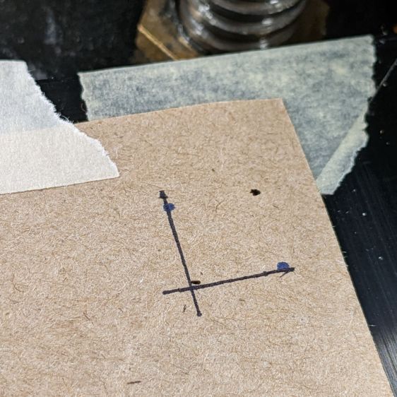
Burn some holes and draw lines 10 mm in from the physical corners, like this:
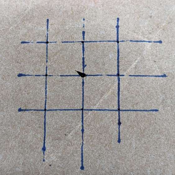
Burn holes and lay in a 10 mm grid at the center point:
The center grid as seen through the camera:
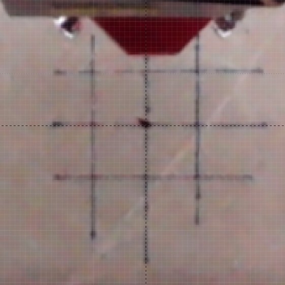
That’s after adjusting the X and Y offset to align the center of the imaged grid with the center of the design grid. That’s using the non-faded image to make the target lines more visible.
The corner markers don’t quite line up with the grid, but they’re not off by much (using the faded image to make the grid more visible):
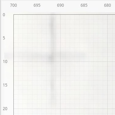

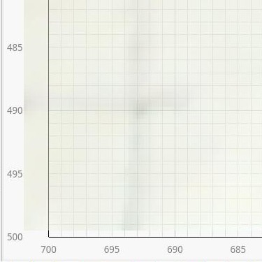
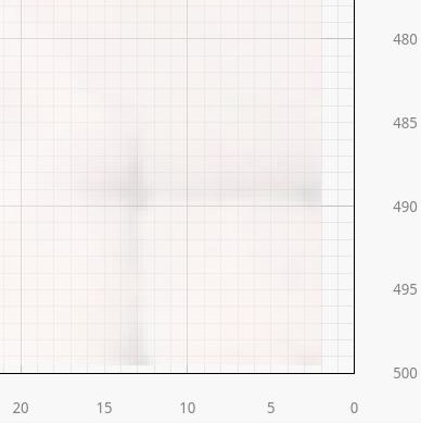
You could, of course, split the difference among all five sites, but I think having the middle of the platform be more accurate than the far corners makes more sense.
In any event, a few millimeters works for most purposes, even if you’d want to verify the alignment for critical operations before firing the laser in earnest.
