Ed Nisley's Blog: Shop notes, electronics, firmware, machinery, 3D printing, laser cuttery, and curiosities. Contents: 100% human thinking, 0% AI slop.
Category: Software
General-purpose computers doing something specific
The hack I added to the lightdm startup script occasionally causes it to hang, which suggests a timing problem. The result leaves the default text-mode login screen active on VT1, after which I can log in and issue sudo lightdm start to produce the usual GUI screen. Using startx doesn’t (seem to) start the display manager, resulting in all manner of weird behavior.
start on ((filesystem
           and runlevel [!06]
           and started dbus
           and (drm-device-added card0 PRIMARY_DEVICE_FOR_DISPLAY=1
                or stopped udev-fallback-graphics)
           and mounted MOUNTPOINT=/mnt/bulkdata)
          or runlevel PREVLEVEL=S)
According to the timing diagram in section 10.1.8, the filesystem event should happen after all the remote filesystems have been mounted, which seems like that stanza might produce a race condition. So just waiting for the filesystem event should suffice, but it doesn’t; that’s why I had to add the mounted event.
According to the example in section 11.14, that stanza should probably look like:
start on ((filesystem
           and (runlevel [!06]
           and (started dbus
           and (drm-device-added card0 PRIMARY_DEVICE_FOR_DISPLAY=1
                or stopped udev-fallback-graphics))))
          or runlevel PREVLEVEL=S)
The additional parentheses around successive conditions seem to serialize them, so that they need not all occur at the same time.
At least I think that’s how it should work…
Unfortunately, it doesn’t. The good news is that it’s converted the intermittent failure into a hard fault, which is generally a step in the right direction.
Changing the stanza to:
#start on ((filesystem
start on ((mounted MOUNTPOINT=/mnt/bulkdata
           and runlevel [!06]
           and started dbus
           and (drm-device-added card0 PRIMARY_DEVICE_FOR_DISPLAY=1
                or stopped udev-fallback-graphics))
#           and mounted MOUNTPOINT=/mnt/bulkdata))
          or runlevel PREVLEVEL=S)
… also fails hard.
At this point, I have no idea what to do, so I’ve restored the original stanza.
More hal-config.lbr tweakage produced enough HAL blocks to completely define the Sherline CNC mill’s HAL connections, all wired up in a multi-page schematic (Eagle-LinuxCNC-Sherline.zip.odt) that completely replaces all the disparate *.hal files I’d been using, plus a new iteration of the hal-write-2.5.ulp Eagle-to-HAL conversion script.
The first sheet (clicky for more dots) defines the manually configured userspace and realtime modules:
Sherline Schematic – 1
That sheet has three types of Eagle devices:
Generalized LoadRT – devices like trivkins that require only a loadrt line
Dedicated LoadRT – devices like motion that require functions connected to a realtime thread
Generalized LoadUsr – devices like hal_input with a HAL device, but no function pins
The device’s NAME field contains either the module name (for the specialized devices with functions) or a generic MODULE for everything else, preceded by an optional index that imposes an ordering on the output lines. The device’s VALUE field contains the text that will become the loadrt or loadusr line in the HAL file. Trailing underscores act as separators, but are discarded by the conversion script.
The immensely long line is the VALUE field that plugs a bunch of variables from the Sherline.ini file into the motion controller.
The conversion script doesn’t do anything special for those devices, other than transfer the VALUE field to the HAL file. Ordinary HAL devices, the ones with functions that don’t require any special setup, must appear in the conversion script’s list of device names, so that it can recognize them and deal with their connections.
Next, the parallel port configuration, which uses the D525’s system board hardware:
Sherline Schematic – 2
The stepconf configuration utility buries the parallel port configuration values in the default HAL file as magic numbers. I moved them to a new stanza in the INI file, although the syntax may not be robust enough to support multiple cards, ports, and configurations. This, however, works for now:
That LOGIC block is new and serves as an AND gate that produces a combined enable signal for the parallel port. The stepconf utility uses the X axis enable signal, but, seeing as how the Sherline controller doesn’t use the result, none of that matters on my system.
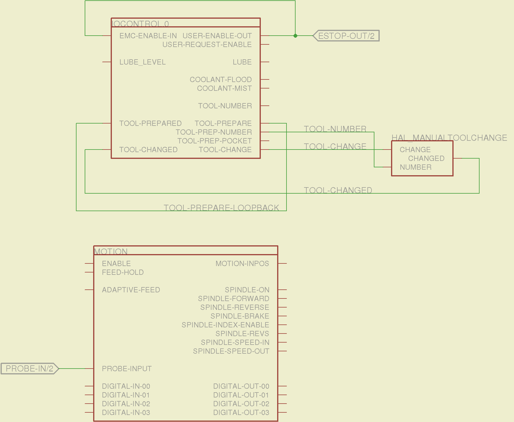
The tool height probe and manual tool change wiring:
Sherline Schematic – 3
I’m not convinced the Emergency Stop polarity is correct, but it matches what was in the original HAL file. As before, the Sherline driver box ignores that output, so none of that matters right now.
Four very similar pages define the XYZA step-and-direction generators. This is the X axis driver:
Sherline Schematic – 4
You can imagine what the next three pages for the YZA logic look like, right? There are also a few blank pages in the schematic, so the numbers jump abruptly.
The magic part of this is having Eagle manage all the tedious renumbering and counting. If you remember to adjust the name of the first module from, say, AXIS.1 to AXIS.0, then the rest get the proper numbers as you go along.
The remainder of the schematic implements the Joggy Thing’s logic, much as described there. I discovered, quite the hard way, that copy-and-pasting an entire schematic from elsewhere does horrible things to the device numbering, but I’m not sure how to combine two schematics to limit the damage. In any event, manually adjusting a few pages wasn’t the worst thing I’ve ever had to do; starting with a unified schematic should eliminate that task in the future.
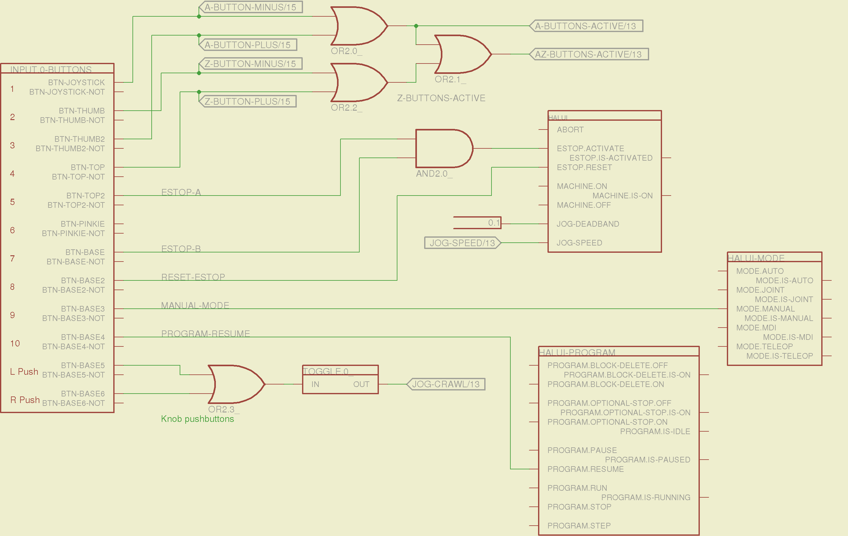
The miscellaneous buttons:
Sherline Schematic – 11
The joystick and hat values:
Sherline Schematic – 12
The joystick deadband logic now uses the (new with HAL 2.5, I think) input.n.abs-x-flat pins, which eliminated a tangle of window comparator logic.
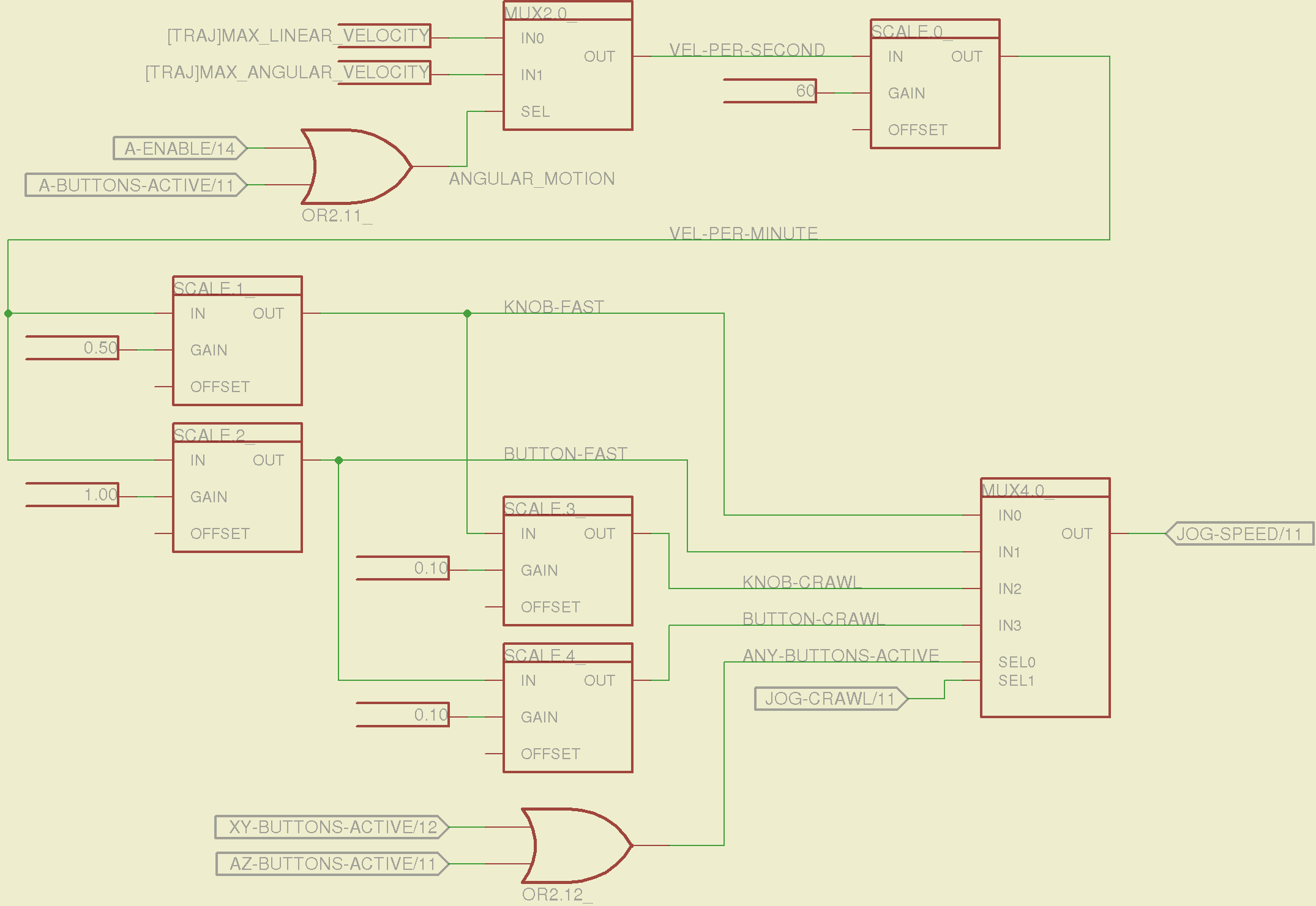
The jog speed adjustment logic that sets the fast and crawl speeds:
Sherline Schematic – 13
I should probably put the speed ratios in the INI file, but that’s in the nature of fine tuning.
The lockout logic that remembers which axis started moving first on a given joystick and locks out the other axis, which greatly simplifies jogging up to an edge without bashing into something else:
Sherline Schematic – 14
Combine all those signals into values that actually tell HAL to jog the axes:
Sherline Schematic – 15
The last page connects all the realtime function pins to the appropriate threads:
Sherline Schematic – 16
The LinuxCNC documentation diverges slightly from the implementation, but a few iterations resolved all the conflicts and had the additional benefit that I had to carefully think through what was actually going on.
A deep and sincere tip o’ the cycling helmet to the folks making LinuxCNC happen!
Although the Sherline mill doesn’t have more than a few minutes of power-on time with the new HAL file, the Joggy Thing behaves as it used to and the axes move correctly, so I think the schematic came out pretty close to the original HAL file.
The next step: draw a new schematic to bring up and exercise a different set of steppers…
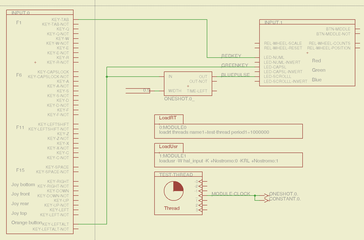
Combining some of the pin names generated by hal_input with the recipe for creating HAL devices, here’s a test configuration that hitches an old Nostromo N52 controller to a LinuxCNC system (clicky for more dots):
Nostromo N52 Controller – HAL config
The F01 key lights the red LED, the Orange Button lights the green LED, and a oneshot timer pulses the blue LED for half a second after the Button closes. The Thread block defines the connections from the functions to the main timing routine, and the loadrt block defines the thread timing. The hal_input module takes care of its own input sampling in userspace.
Now, for the classic embedded system “Hello, world!” test:
Nostromo N52 Controller – F01 test
It’s amazing how good an LED can make you feel…
A halscope shot shows the timing relation between the Orange Button (confusingly hitched to the greenkey signal) and the oneshot pulse:
HalScope – oneshot triggering
That schematic produces this HAL configuration file:
# HAL config file automatically generated by Eagle-CAD ULP:
# [/mnt/bulkdata/Project Files/eagle/ulp/hal-write-2.5.ulp]
# (C) Martin Schoeneck.de 2008
# Charalampos Alexopoulos 2011
# Mods Ed Nisley KE4ZNU 2010 2013
# Path        [/mnt/bulkdata/Project Files/eagle/projects/LinuxCNC HAL Configuration/]
# ProjectName [Nostromo]
# File name   [/mnt/bulkdata/Project Files/eagle/projects/LinuxCNC HAL Configuration/Nostromo.hal]
# Created     [12:28:04 14-Feb-2013]

####################################################
# Load realtime and userspace modules
loadrt threads name1=test-thread period1=1000000
loadusr -W hal_input -K +Nostromo:0 -KRL +Nostromo:1
loadrt constant		count=1
loadrt oneshot		count=1

####################################################
# Hook functions into threads
addf oneshot.0		test-thread
addf constant.0		test-thread

####################################################
# Set parameters

####################################################
# Set constants
setp constant.0.value	0.5

####################################################
# Connect Modules with nets
net bluepulse input.1.led-scrolll oneshot.0.out
net duration constant.0.out oneshot.0.width
net greenkey input.0.key-leftalt oneshot.0.in input.1.led-capsl
net redkey input.0.key-tab input.1.led-numl
A snapshot of the Nostromo.sch, Nostromo.hal, hal_config.lbr, and hal-write-2.5.ulp files is in Nostromo-N52.zip.odt. Rename it to get rid of the ODT suffix, unzip it, and there you go.
Yes, thank you so much! Everything you said was true. Apparently someone’s USB drive was infected and infected many computers here. We are very appreciative for your technological detective work. The head of IT was very incredulous because everything is deep frozen after it is shut down. But it was all true and I am very grateful
The part about “many computers here” seems worrisome; they’re apparently not running any defensive software at all.
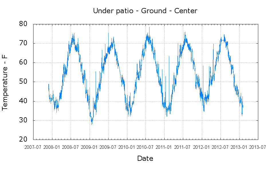
The patio at the rear of our house is a six inch concrete slab with a five foot “crawlspace” below it, with a HOBO datalogger pendant in the dirt near the pole at the middle of the I beam supporting the slab. The pendant is very close to the surface, so there’s a big diurnal temperature variation, but it still gives a reasonable picture of seasonal change.
A configuration setting in Hoboware determines whether it stores / exports dates with years having two digits or four digits. As you might expect, over the course of five years the dates have both formats, but there’s always a blank separating the date and the time:
grep "/12 " /tmp/data.csv | head -1
1,11/09/12 08:45:00 ,49.050,,,,
grep "/2012 " /tmp/data.csv | head -1
2235,01/01/2012 00:00:00,44.560,0.0,,,,
This burst of sed regex line noise normalizes all years to four digits:
sed 's/\/\([0-9][0-9]\) /\/20\1 /' whatever.csv
The parenthesized subexpression matches the digits of a two digit year preceding a blank, then the \1 plugs it into the right spot in the output. This suffers from the usual failure when the century rolls over, but frankly, my dear readers, I don’t give a damn. The backslashes escape forward slashes and parentheses, in addition to making the regex pretty much write-only.
The plot shows the expected annual variation:
Under patio – Ground – Center
The periodic upward spikes happen when I carry the logger to the Token Windows Laptop and read it out; the air temperature upstairs is always warmer than the dirt under the patio.
The Bash and gnuplot script that produced the graph:
#!/bin/sh
#-- overhead
export GDFONTPATH="/usr/share/fonts/truetype/"
base="${1%.*}"
echo Base name: ${base}
ofile=${base}.png
tfile=$(tempfile)
echo Input file: $1
echo Temporary file: ${tfile}
echo Output file: ${ofile}
#-- prepare csv Hobo logger file
sed 's/^\"/#&/' "$1" | sed 's/^.*Logged/#&/' | sed 's/ ,/,/' | sed 's/\/\([0-9][0-9]\) /\/20\1 /' > ${tfile}
#-- do it
gnuplot << EOF
#set term x11
set term png font "arialbd.ttf" 18 size 950,600
set output "${ofile}"
set title "${base}"
set key noautotitles
unset mouse
set bmargin 4
set grid xtics ytics
set timefmt "%m/%d/%Y %H:%M:%S"
set xdata time
set xlabel "Date"
set format x "%Y-%m"
#set xrange [1.8:2.2]
set xtics font "arial,12"
#set mxtics 2
#set logscale y
#set ytics nomirror autofreq
set ylabel "Temperature - F"
#set format y "%4.0f"
#set yrange [30:90]
#set mytics 2
#set y2label "right side variable"
#set y2tics nomirror autofreq 2
#set format y2 "%3.0f"
#set y2range [0:200]
#set y2tics 32
#set rmargin 9
set datafile separator ","
#set label 1 "label text" at 2.100,110 right font "arialbd,18"
#set arrow from 2.100,110 to 2.105,103 lt 1 lw 2 lc 0
plot	\
    "${tfile}" using 2:3 with lines lt 3
EOF
To that end, here’s a checklist for creating a new Eagle device corresponding to a HAL module.
Remember: although this process has a tremendous number of moving parts, you do it exactly once when you need a device that doesn’t already exist. After that, you just click to add an existing device to your schematic, wire it up, then the tedious write-only HAL overhead happens automagically.
Cross-check the documentation with the actual component code!
The man page lists the names, pins, parameters, and suchlike, but may have typos. This isn’t a criticism, it’s a fact of life.
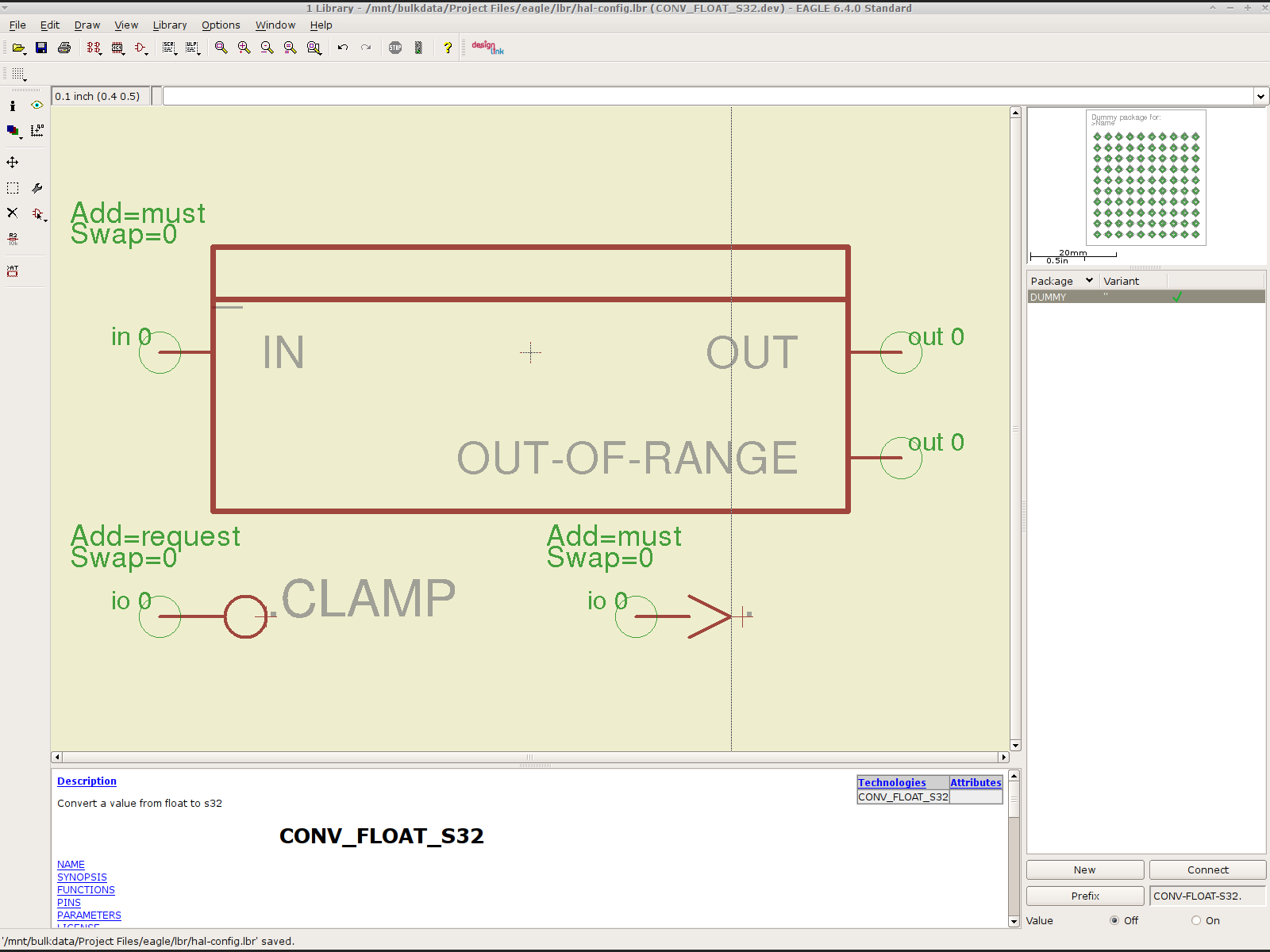
Before investing a ton o’ time creating an Eagle device, load the module and find out what’s really there:
halrun
halcmd: loadrt conv_float_s32
halcmd: show all
Loaded HAL Components:
ID      Type  Name                                      PID   State
     4  RT    conv_float_s32                                  ready
     3  User  halcmd2395                                 2395 ready

Component Pins:
Owner   Type  Dir         Value  Name
     4  float IN              0  conv-float-s32.0.in
     4  s32   OUT             0  conv-float-s32.0.out
     4  bit   OUT         FALSE  conv-float-s32.0.out-of-range

... snippage ...

Parameters:
Owner   Type  Dir         Value  Name
     4  bit   RW          FALSE  conv-float-s32.0.clamp
     4  s32   RO              0  conv-float-s32.0.time
     4  s32   RW              0  conv-float-s32.0.tmax

... snippage ...

Exported Functions:
Owner   CodeAddr  Arg       FP   Users  Name
 00004  fc0a9000  fc0630b8  YES      0   conv-float-s32.0
... snippage ...
Achtung!
The module name uses underscores as separators: loadrt conv_float_s32
The function name uses h-y-p-h-e-n-s as separators: conv-float-s32.0
Unlike in the Linux kernel, the two characters are not equivalent
Add the HAL Module to the Conversion Script
The hal-write.ulp script contains a table of all the module names, so you must update the script in parallel with the hal-config.lbr Eagle library.
However, you can create an Eagle device that is not a HAL module by omitting it from the script. In that case, the Eagle device name will become part of the net names that define and interconnect the pins, but the script will not create a statement to load a module. For example, the hal_input userspace program creates a set of pins for each input device that start with input.n, but there’s no corresponding HAL module. I’ll put up an example of all this in a bit.
Create a Schematic Symbol
The name of the symbol is not critical: CONVERT.sym
use either dashes or hyphens as you prefer
The >NAME string must be on layer 95-Names
No need for a >VALUE string, but put it on layer 96-Values if present
HAL pins become symbol pins
Use the HAL pin name, with hyphens
Set Visibility to Pin
Set Direction to in / out / io to match the HAL description
Set Function to None to indicate an ordinary net connection
Verify the pins against the HAL device!
Create a HAL Schematic Device
The new device name must match the HAL module name, with underscores, as entered in the conversion script table
CONV_FLOAT_S32.dev
Set the Prefix to the HAL function name, plus a trailing period, with hyphens
CONV-FLOAT-S32.
Create the Description using copy-and-paste from the HTML source: use the man page in the LinuxCNC doc
Ctrl-U in Firefox reveals the HTML source, Ctrl-A and Ctrl-C, flip windows, then Ctrl-V
Delete all the boilerplate at the top, leave the centered Title, ditch the reference links
Add the symbol you created earlier or reuse an existing symbol
Set the symbol NAME to a single underscore: _
Change the Add level to must
Add a PIN_FUNCTION symbol to the device
Change the symbol name from G$1 (or whatever) to a single period: .
Change the Add Level to must
Add PIN_PARAMETER symbols as needed
Change the symbol name from G$1 (or whatever) to the parameter name preceded by a single period: .CLAMP
Change the Add Level to request
Change the Direction as needed
Add the DUMMY physical package, then connect all the pins to pads
Create a non-HAL Schematic Device
The new device name may be anything that’s not in the conversion script table
The Prefix must match the desired pin names, plus a trailing period. For hal_input pins:
INPUT.
Create the Description as above
Add the symbol you created earlier
Set the symbol NAME to a single underscore: _
Change the Add level to must
Do not add a PIN_FUNCTION symbol, because it has no corresponding module
Add PIN_PARAMETER symbols as needed
Change the symbol name from G$1 (or whatever) to the parameter name preceded by a single period: .CLAMP
Change the Add Level to request
Change the Direction as needed
Add the DUMMY physical package, then connect all the pins to pads
Devices may have multiple Symbols, with different Add Level options; can seems appropriate. As nearly as I can tell, you must name each Symbol as a suffix to the full name to differentiate them within the Device; I use a hyphen before the suffix, so that -KEYS generates INPUT.0-KEYS. Those suffixes don’t appear elsewhere in the generated HAL configuration file.
Save the library, update it in the schematic editor (Library → Update ...), and you’re set.
Although it’s tempting, do not include a version number in the library file name, because Eagle stores the file name inside the schematic file along with the devices from that file. As a result, when you bump the library version number and use devices from the new library file, the schematic depends on both library files and there’s no way within Eagle to migrate devices from one library to the other; you must delete the existing devices from the schematic and re-place them from the new library. Or you can do like I did: hand-edit the XML fields inside the library file.
Eagle HAL Device
You’ll almost certainly drive this procedure off the rails, so let me know what I’ve screwed up. It does, in fact, work wonderfully well and, as far as I’m concerned, makes HAL usable, if only because HAL is a write-only language to start with and now you need not read it to modify it.
A (formerly Belkin, now Razer, which is evidently unrelated to Mazer Rackham) Nostromo N52 SpeedPad might not be a perfect CNC pendant, but it does have plenty of buttons and an (oddly oriented) XY joypad that might be useful for, say, a 3D printer controller running LinuxCNC.
Belkin Nostromo N52 SpeedPad
Following the same path as with the Logitech Dual Action Gamepad that became the Joggy Thing, we find that the N52 reports itself as a keyboard and a mouse:
udevadm info --query=all --attribute-walk --name=/dev/bus/usb/002/004

Udevadm info starts with the device specified by the devpath and then
walks up the chain of parent devices. It prints for every device
found, all possible attributes in the udev rules key format.
A rule to match, can be composed by the attributes of the device
and the attributes from one single parent device.

  looking at device '/devices/pci0000:00/0000:00:02.0/usb2/2-10':
    KERNEL=="2-10"
    SUBSYSTEM=="usb"
    DRIVER=="usb"
    ATTR{configuration}==""
    ATTR{bNumInterfaces}==" 2"
    ATTR{bConfigurationValue}=="1"
    ATTR{bmAttributes}=="80"
    ATTR{bMaxPower}==" 90mA"
    ATTR{urbnum}=="1354"
    ATTR{idVendor}=="050d"
    ATTR{idProduct}=="0815"
    ATTR{bcdDevice}=="0210"
    ATTR{bDeviceClass}=="00"
    ATTR{bDeviceSubClass}=="00"
    ATTR{bDeviceProtocol}=="00"
    ATTR{bNumConfigurations}=="1"
    ATTR{bMaxPacketSize0}=="8"
    ATTR{speed}=="1.5"
    ATTR{busnum}=="2"
    ATTR{devnum}=="4"
    ATTR{version}==" 1.10"
    ATTR{maxchild}=="0"
    ATTR{quirks}=="0x0"
    ATTR{authorized}=="1"
    ATTR{manufacturer}=="Honey Bee "
    ATTR{product}=="Nostromo SpeedPad2 "

... snippage ...
Note the trailing blank in the manufacturer and product values.
Create a new rules file /etc/udev/rule/90-Nostromo.rules to change the group and permissions:
# Belkin Nostromo N52 SpeedPad controller for LinuxCNC
# Ed Nisley - KE4ZNU - February 2013

ATTRS{product}=="Nostromo SpeedPad2",GROUP="plugdev",MODE="0660"
Note that the file name must start with a number around 90- to avoid being clobbered by a rule in /lib/udev/rules.d/50-udev-default.rules that (re)sets the permissions to 0640; the doc suggests that rules without numbers happen after all the number rules, so perhaps you could just use meaningful names. That took an embarrassingly long time to figure out…
There’s no need for the trailing blank in that rule, as the match proceeds left-to-right and stops at the end of the test string.
You must, perforce, be in the plugdev group. If not, add yourself.
You need not unplug the N52 to test the rule. Just use:
The + prefix tells HAL to capture the named device and prevent its events from reaching X. The KRL codes suggest which functions you’re interested in for that particular device. The suffix digit selects successive devices for multiple gadgets matching the same name string.
Apparently, the N52 reports it can produce all the usual keyboard and mouse values & buttons, even if they’re not connected to physical hardware. I suspect it has generic keyboard / mouse controllers inside, with just a few of the usual matrix crosspoints connected to switches.
The basic key mapping, sorted by the Nostromo functions:
Type
Dir
Name
Nostromo key
bit
OUT
input.0.key-tab
F1
bit
OUT
input.0.key-q
F2
bit
OUT
input.0.key-w
F3
bit
OUT
input.0.key-e
F4
bit
OUT
input.0.key-r
F5
bit
OUT
input.0.key-capslock
F6
bit
OUT
input.0.key-a
F7
bit
OUT
input.0.key-s
F8
bit
OUT
input.0.key-d
F9
bit
OUT
input.0.key-f
F10
bit
OUT
input.0.key-leftshift
F11
bit
OUT
input.0.key-z
F12
bit
OUT
input.0.key-x
F13
bit
OUT
input.0.key-c
F14
bit
OUT
input.0.key-space
F15
bit
OUT
input.0.key-leftalt
Orange button
bit
OUT
input.0.key-right
Pad bottom
bit
OUT
input.0.key-down
Pad front
bit
OUT
input.0.key-up
Pad rear
bit
OUT
input.0.key-left
Pad top
bit
OUT
input.1.btn-middle
Wheel press
s32
OUT
input.1.rel-wheel-counts
Scroll wheel
bit
IN
input.1.led-numl
Red LED
bit
IN
input.1.led-capsl
Green LED
bit
IN
input.1.led-scrolll
Blue LED
The bit pins also have inverted values available on the corresponding -not pins. The LEDs have an -invert that flips the sense of the input pin. The rel-wheel pin has other useful tidbits as suffixes; the count changes by ±1 for each wheel detent.
The Tab key and all the letters auto-repeat, the various Shift and Alt keys do not. That seems to make no difference to the bit values reported by HAL.