Ed Nisley's Blog: Shop notes, electronics, firmware, machinery, 3D printing, laser cuttery, and curiosities. Contents: 100% human thinking, 0% AI slop.
Category: Software
General-purpose computers doing something specific
Having just acquired a pair of 64 GB MicroSD cards for the HDR-AS30V camera, I found that I don’t have enough free disk space for 64 GB of white noise and, thus, can’t use the same technique as for the 32 GB card. I now, however, have a stockpile of helmet camera video files that are close enough to white noise for my purposes and come in convenient chunks.
Start by copying enough big video files to nearly fill the card:
sudo mount /dev/sdb1 /mnt/backup
sudo mount -o uid=ed /dev/sdc1 /mnt/part
FUSE exfat 1.0.1
cd /mnt/backup/Video
find -iname MAH*MP4 -size +3G | head -16 | xargs -I{} rsync -vrt --progress {} /mnt/part
sending incremental file list
MAH00122.MP4
  4,275,755,727 100%   11.94MB/s    0:05:41 (xfr#1, to-chk=0/1)

sent 4,276,799,695 bytes  received 35 bytes  12,487,006.51 bytes/sec
total size is 4,275,755,727  speedup is 1.00
... snippage ...
The head -16 ensures that you won’t waste a lot of time copying too many files. The card has about 59 GB free, so 16 x 4 GB is about right.
The -vrt adds verbosity and omits permission settings that ExFAT doesn’t understand; otherwise, you’d just use -va and be done with it.
Then tuck some smaller files into the remaining nooks and crannies:
Some fiddling with the -size -400M and head -16 values may be in order, depending on how many snippets of video data you may have.
Compare the copies with the original files:
cd /mnt/part
for f in * ; do find /mnt/backup/Video/ -name $f | xargs diff $f ; done
If you don’t see anything, then they’re all good!
There’s probably an algorithmic solution that would eliminate the guesstimation, but very nearly all of the time goes to copying and comparing, so it can’t make much difference.
Took a picture of the sewing machine setup with the Sony DSC-F717, transferred it into DigiKam, got the “done transferring, you can disconnect the camera” message, believed it, disconnected the camera, deleted the image file, and then discovered that DigiKam mislaid the image file.
Rather than re-set-up and re-take the shot, I followed my own directions and recovered the image from the Memory Stick:
dmesg | tail
[43176.079853] usb 2-1.6.3: New USB device strings: Mfr=1, Product=2, SerialNumber=0
[43176.079855] usb 2-1.6.3: Product: Sony PTP
[43176.079856] usb 2-1.6.3: Manufacturer: Sony
[43198.073652] usb 2-1.6.3: USB disconnect, device number 22
[43333.788533] sd 9:0:0:0: [sdc] 1947648 512-byte logical blocks: (997 MB/951 MiB)
[43333.803292] sd 9:0:0:0: [sdc] No Caching mode page found
[43333.803299] sd 9:0:0:0: [sdc] Assuming drive cache: write through
[43333.824681] sd 9:0:0:0: [sdc] No Caching mode page found
[43333.824688] sd 9:0:0:0: [sdc] Assuming drive cache: write through
[43333.825491]  sdc: sdc1
sudo dd if=/dev/sdc of=/tmp/pix.bin bs=1M
^C615+0 records in
614+0 records out
643825664 bytes (644 MB) copied, 38.5841 s, 16.7 MB/s
strings -t x pix.bin | grep Exif | head
  68006 Exif
 208006 Exif
 3f8005 _Exif
 7b8006 Exif
13d8006 Exif
15b0005 wExif
1798005 CExif
19c0006 Exif
1b90006 Exif
1f98005 %Exif
dd if=pix.bin of=image03.jpg bs=$((16#1000)) count=1K skip=$((16#3f8))
1024+0 records in
1024+0 records out
4194304 bytes (4.2 MB) copied, 0.0121431 s, 345 MB/s
display image03.jpg
convert image03.jpg dsc00656.jpg
Obviously, there was a bit more flailing around than you see here, but that’s the gist of the adventure. For what it’s worth, image01 was a random blurred shot and image02 is the ID picture I keep on all my cameras.
The convert step discards all the junk after the end of the image, so the dsc00656.jpg file doesn’t include anything unexpected.
The picture isn’t all that much to look at, even after cropping out the background, but …
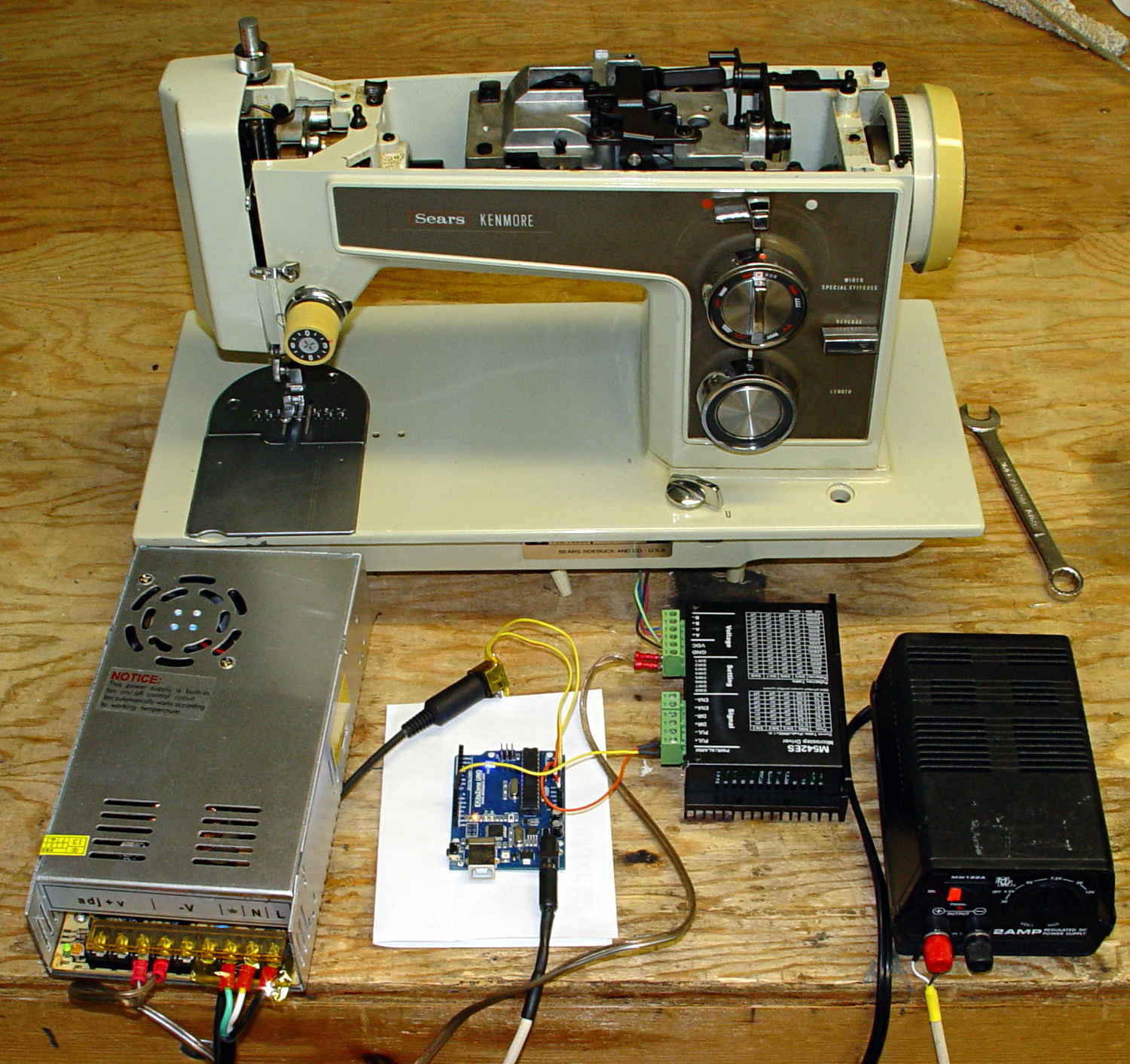
Kenmore 158 – stepper drive test
The advantage of the manual method: renewing one’s acquaintance with tools that come in handy for other tasks.
For some reason, WordPress chokes when uploading the starting shape as a PNG file, so here it is as a JPG with a black border replacing the original transparency:
gel_shape
With the gel highlight:
gel_highlight
Adding a border:
gel_border
Adding text, shadow, and background:
gel_button
Adding the drop shadow may increase the image size ever so slightly, so the -repage 0x0+7+7 operation may require resetting the exact image size.
The smaller buttons came directly from The GIMP, with full-frontal manual control over everything. Obviously, that doesn’t scale well for many buttons that should all look pretty much the same, because you want to get your fingers out of the loop.
But, obviously, when you do this on a mass scale, you want better control over the colors and text and suchlike; that’s in the nature of fine tuning when it’s needed.
I’m not entirely convinced I want gel-flavored buttons, but it was a fun exercise.
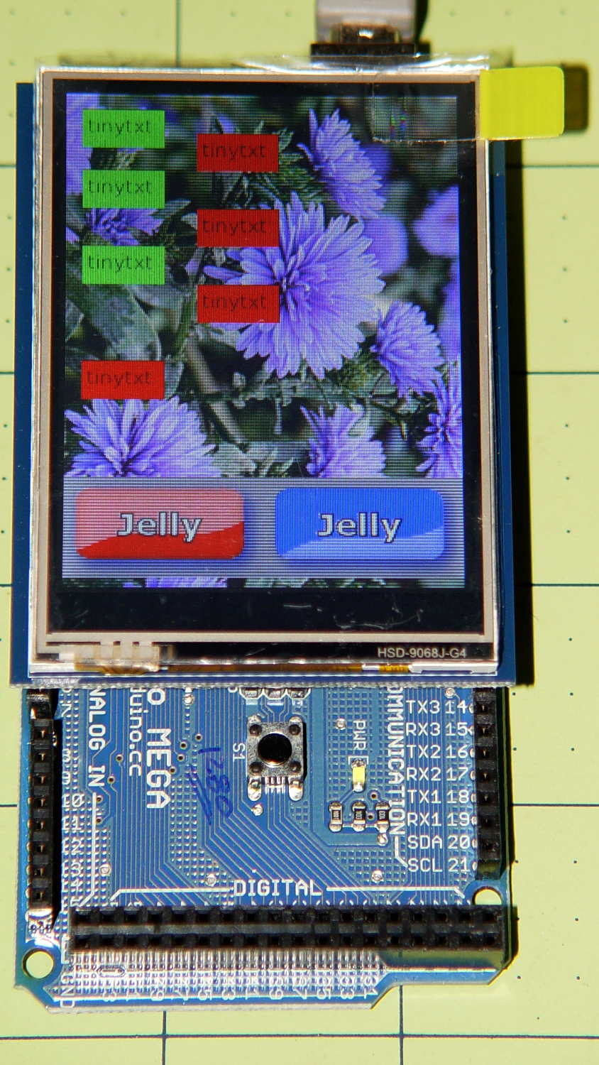
The Adafruit 2.8 inch TFT Touch Shield for Arduino v2 seems just about ideal for a small control panel, such as one might use with a modified sewing machine. All you need is a few on-screen buttons, a few status display, and a bit of Arduino love: what more could one ask?
So I gimmicked up some small buttons with GIMP, made two large buttons with ImageMagick, and lashed together some Arduino code based on the Adafruit demo:
Adafruit TFT display – timing demo
The picture doesn’t do justice to the display: it’s a nice piece of hardware that produces a crisp image. The moire patterns come from the interaction of TFT display pixels / camera pixels / image resizing.
It’s not obvious from the Adafruit description, but the display is inherently portrait-mode as shown. The (0,0) origin lies in the upper left corner, just over the DC power jack, and screen buffer updates proceed left-to-right, top-to-bottom from there.
The gotcha: even with the Arduino Mega’s hardware SPI, writing the full display requires nearly 4 seconds. Yeah, slow-scan TV in action. Writing the screen with a solid color requires several seconds.
After commenting out the serial tracing instructions from the Adafruit demo and tweaking a few other things, these timings apply:
-------------
Writing background
Elapsed: 3687
Writing six buttons
Elapsed: 529
Overwriting six buttons
Elapsed: 531
Rewriting buttons 10 times
Elapsed: 1767
Overwriting 2 large buttons
Elapsed: 1718
The button images come from BMP files on a MicroSD card and 8 KB of RAM won’t suffice for even a small button. Instead, the transfer loop buffers 20 pixels = 60 bytes from the card, writes them to the display, and iterates until it’s done.
Trust me on this: watching the buttons gradually change is depressing.
Yes, it could work as a control panel for the sewing machine, but it doesn’t have nearly the pep we’ve come to expect from touch-screen gadgetry. On the other paw, Arduinos are 8-bit microcontrollers teleported from the mid-90s, when crappy 20×4 LCD panels were pretty much as good as it got.
The SPI hardware clock runs at half the oscillator frequency = 16 MHz/2 = 8 MHz = 125 ns/bit. Clocking a single byte thus requires 1 µs; even allowing that each pixel = 3 bytes = 6 SPI operations, there’s a lot of software overhead ripe for the chopping block. I’d be sorely tempted to write a pair of unrolled loops that read 20 pixels and write 20 pixels with little more than a pointer increment & status spin between successive SPI transfers.
It’ll make hotshot C++ programmers flinch, but splicing all that into a single routine, throwing out all the clipping and error checking, and just getting it done might push the times down around 20 µs/pixel. Admittedly, that’s barely twice as fast, but should be less depressing.
However, even with all that effort, the time required to update the screen will clobber the motor control. You can’t devote a big fraction of a second to rewriting a button at the same time you’re monitoring the pedal position, measuring the motor speed, and updating the control voltage. That’s the same problem that makes Arduino microcontrollers inadequate for contemporary 3D printers: beyond a certain point, the hardware is fighting your efforts, not helping you get things done.
A reasonable workaround: no screen updates while the motor turns, because you shouldn’t have any hands free while you’re sewing.
The Arduino source code, hacked from the Adafruit demo:
// 2.8 inch TFT display exercise
// Crudely hacked from Adafruit demo code: spitftbitmap.ino
// 2014-07-03 Ed Nisley KE4ZNU

/***************************************************
  This is our Bitmap drawing example for the Adafruit ILI9341 Breakout and Shield
  ----> http://www.adafruit.com/products/1651

  Check out the links above for our tutorials and wiring diagrams
  These displays use SPI to communicate, 4 or 5 pins are required to
  interface (RST is optional)
  Adafruit invests time and resources providing this open source code,
  please support Adafruit and open-source hardware by purchasing
  products from Adafruit!

  Written by Limor Fried/Ladyada for Adafruit Industries.
  MIT license, all text above must be included in any redistribution
 ****************************************************/

#include <Adafruit_GFX.h>    // Core graphics library
#include "Adafruit_ILI9341.h" // Hardware-specific library
#include <SPI.h>
#include <SD.h>

#define TFT_DC 9
#define TFT_CS 10
Adafruit_ILI9341 tft = Adafruit_ILI9341(TFT_CS, TFT_DC);

#define SD_CS 4

unsigned long MillisNow, MillisThen;

void setup(void) {
  Serial.begin(115200);

  tft.begin();
  tft.fillScreen(ILI9341_BLACK);

  Serial.print(F("Initializing SD card..."));
  if (!SD.begin(SD_CS)) {
    Serial.println(F("failed!"));
  }
  Serial.println(F("OK!"));

}

void loop() {
  Serial.println(F("--------------"));
  Serial.println(F("Writing background"));
  MillisThen = millis();

  bmpDraw("Test1.bmp", 0, 0);

  MillisNow = millis();
  Serial.print(F("" Elapsed: ""));
  Serial.println(MillisNow - MillisThen);

  Serial.println(F("Writing 6 small buttons"));
  MillisThen = millis();

  bmpDraw("Red50x25.bmp",10,10);
  bmpDraw("Red50x25.bmp",10,50);
  bmpDraw("Red50x25.bmp",10,100);

  bmpDraw("Grn50x25.bmp",80,25);
  bmpDraw("Grn50x25.bmp",80,75);
  bmpDraw("Grn50x25.bmp",80,125);

  MillisNow = millis();
  Serial.print(F("" Elapsed: ""));
  Serial.println(MillisNow - MillisThen);

  Serial.println(F("Overwriting 6 small buttons"));
  MillisThen = millis();

  bmpDraw("Grn50x25.bmp",10,10);
  bmpDraw("Grn50x25.bmp",10,50);
  bmpDraw("Grn50x25.bmp",10,100);

  bmpDraw("Red50x25.bmp",80,25);
  bmpDraw("Red50x25.bmp",80,75);
  bmpDraw("Red50x25.bmp",80,125);

  MillisNow = millis();
  Serial.print(F("" Elapsed: ""));
  Serial.println(MillisNow - MillisThen);

  Serial.println(F("Writing small button 10x2 times"));
  MillisThen = millis();

  for (byte i=0; i<10; i++) {
    bmpDraw("Grn50x25.bmp",10,175);
    bmpDraw("Red50x25.bmp",10,175);
  }

  MillisNow = millis();
  Serial.print(F("" Elapsed: ""));
  Serial.println(MillisNow - MillisThen);

  Serial.println(F("Overwriting 2 large buttons"));
  MillisThen = millis();

  bmpDraw("GelDn.bmp",0,250);
  bmpDraw("GelUp.bmp",0,250);

  bmpDraw("GelUp.bmp",120,250);
  bmpDraw("GelDn.bmp",120,250);

  MillisNow = millis();
  Serial.print(F("" Elapsed: ""));
  Serial.println(MillisNow - MillisThen);

}

// This function opens a Windows Bitmap (BMP) file and
// displays it at the given coordinates.  It's sped up
// by reading many pixels worth of data at a time
// (rather than pixel by pixel).  Increasing the buffer
// size takes more of the Arduino's precious RAM but
// makes loading a little faster.  20 pixels seems a
// good balance.

#define BUFFPIXEL 20

void bmpDraw(char *filename, uint8_t x, uint16_t y) {

  File     bmpFile;
  int      bmpWidth, bmpHeight;   // W+H in pixels
  uint8_t  bmpDepth;              // Bit depth (currently must be 24)
  uint32_t bmpImageoffset;        // Start of image data in file
  uint32_t rowSize;               // Not always = bmpWidth; may have padding
  uint8_t  sdbuffer[3*BUFFPIXEL]; // pixel buffer (R+G+B per pixel)
  uint8_t  buffidx = sizeof(sdbuffer); // Current position in sdbuffer
  boolean  goodBmp = false;       // Set to true on valid header parse
  boolean  flip    = true;        // BMP is stored bottom-to-top
  int      w, h, row, col;
  uint8_t  r, g, b;
  uint32_t pos = 0, startTime = millis();

  if((x >= tft.width()) || (y >= tft.height())) return;

//  Serial.println();
//  Serial.print(F("Loading image '"));
//  Serial.print(filename);
//  Serial.println('\'');

  // Open requested file on SD card
  if ((bmpFile = SD.open(filename)) == NULL) {
//    Serial.print(F("File not found"));
    return;
  }

  // Parse BMP header
  if(read16(bmpFile) == 0x4D42) { // BMP signature
//    Serial.print(F("File size: "));
//	Serial.println(read32(bmpFile));
	read32(bmpFile);
    (void)read32(bmpFile); // Read & ignore creator bytes
    bmpImageoffset = read32(bmpFile); // Start of image data
//    Serial.print(F("Image Offset: ")); Serial.println(bmpImageoffset, DEC);
    // Read DIB header
//    Serial.print(F("Header size: "));
//	Serial.println(read32(bmpFile));
	read32(bmpFile);
    bmpWidth  = read32(bmpFile);
    bmpHeight = read32(bmpFile);
    if(read16(bmpFile) == 1) { // # planes -- must be '1'
      bmpDepth = read16(bmpFile); // bits per pixel
//      Serial.print(F("Bit Depth: ")); Serial.println(bmpDepth);
      if((bmpDepth == 24) && (read32(bmpFile) == 0)) { // 0 = uncompressed

        goodBmp = true; // Supported BMP format -- proceed!
//        Serial.print(F("Image size: "));
//        Serial.print(bmpWidth);
//        Serial.print('x');
//        Serial.println(bmpHeight);

        // BMP rows are padded (if needed) to 4-byte boundary
        rowSize = (bmpWidth * 3 + 3) & ~3;

        // If bmpHeight is negative, image is in top-down order.
        // This is not canon but has been observed in the wild.
        if(bmpHeight < 0) {
          bmpHeight = -bmpHeight;
          flip      = false;
        }

        // Crop area to be loaded
        w = bmpWidth;
        h = bmpHeight;
        if((x+w-1) >= tft.width())  w = tft.width()  - x;
        if((y+h-1) >= tft.height()) h = tft.height() - y;

        // Set TFT address window to clipped image bounds
        tft.setAddrWindow(x, y, x+w-1, y+h-1);

        for (row=0; row<h; row++) { // For each scanline...

          // Seek to start of scan line.  It might seem labor-
          // intensive to be doing this on every line, but this
          // method covers a lot of gritty details like cropping
          // and scanline padding.  Also, the seek only takes
          // place if the file position actually needs to change
          // (avoids a lot of cluster math in SD library).
          if(flip) // Bitmap is stored bottom-to-top order (normal BMP)
            pos = bmpImageoffset + (bmpHeight - 1 - row) * rowSize;
          else     // Bitmap is stored top-to-bottom
            pos = bmpImageoffset + row * rowSize;
          if(bmpFile.position() != pos) { // Need seek?
            bmpFile.seek(pos);
            buffidx = sizeof(sdbuffer); // Force buffer reload
          }

          for (col=0; col<w; col++) { // For each pixel...
            // Time to read more pixel data?
            if (buffidx >= sizeof(sdbuffer)) { // Indeed
              bmpFile.read(sdbuffer, sizeof(sdbuffer));
              buffidx = 0; // Set index to beginning
            }

            // Convert pixel from BMP to TFT format, push to display
            b = sdbuffer[buffidx++];
            g = sdbuffer[buffidx++];
            r = sdbuffer[buffidx++];
            tft.pushColor(tft.color565(r,g,b));
          } // end pixel
        } // end scanline
//        Serial.print(F("Loaded in "));
//        Serial.print(millis() - startTime);
//        Serial.println("" ms"");
      } // end goodBmp
    }
  }

  bmpFile.close();
  if(!goodBmp) Serial.println(F("BMP format not recognized."));
}

// These read 16- and 32-bit types from the SD card file.
// BMP data is stored little-endian, Arduino is little-endian too.
// May need to reverse subscript order if porting elsewhere.

uint16_t read16(File &f) {
  uint16_t result;
  ((uint8_t *)&result)[0] = f.read(); // LSB
  ((uint8_t *)&result)[1] = f.read(); // MSB
  return result;
}

uint32_t read32(File &f) {
  uint32_t result;
  ((uint8_t *)&result)[0] = f.read(); // LSB
  ((uint8_t *)&result)[1] = f.read();
  ((uint8_t *)&result)[2] = f.read();
  ((uint8_t *)&result)[3] = f.read(); // MSB
  return result;
}
It turns out that the clever idea of moving the swap partition to a USB flash drive had no effect whatsoever; the UI continued to freeze up during OpenSCAD compiles and suchlike, with the drive activity light on solid and not much in the way of swap activity. Sooo, I wondered what would happen with the /tmp directory on non-rotating memory.
Then I spotted a sale on a Samsung 840 EVO 120 GB solid state drive, which seemed like it might improve almost everything in one swell foop. That’s a tiny drive, at least by contemporary standards, but all my data files live downstairs on the file server, so the desktop drive holds just the Xubuntu installation.
It’s worth noting that SSDs tend to fail suddenly and catastrophically, so that if the only copy of your data is on that drive, there is no recovery. In this case, I’d lose some configuration that changes with every installation, a few locally installed / compiled-from-source programs, and little else.
The nice thing about transferring a Linux installation: boot a live CD image (I used Ubuntu 14.04LTS, the same as the desktop box), copy the files to the new drive, set up Grub, and you’re back on the air. That recipe worked fine, although I used rsync -au to copy the files and then updated /etc/fstab with the SSD’s new UUID (rather than duplicate a supposedly unique ID).
The Grub recipe does require a bit of delicate surgery, so I removed the OEM hard drive and rebooted the live CD image before doing this. If the SSD fell victim to a finger fumble, I could just start over again:
sudo mount /dev/sda1 /mnt
for f in dev proc sys usr ; do sudo mount --bind /$f /mnt/$f ; done
sudo chroot /mnt
sudo update-grub
sudo grub-install /dev/sda
sudo grub-install --recheck /dev/sda
exit
for f in dev proc sys usr ; do sudo umount /mnt/$f ; done
sudo umount /mnt
Then reboot from the SSD and It Just Worked.
Dropbox and DigiKam noticed the UUID change and asked for advice; there’s no need for re-registration, re-activation, or re-authorization.
The overall time from boot to login isn’t much shorter, because of the tedious delay while the network and the NFS shares get up & running, but the desktop UI startup zips right along.
The same OpenSCAD compile that previously brought the UI to a halt has no effect, so I hereby declare victory. I think the complex solid models that used to take forever will see much the same speedup.
The Dell hard drive (an ordinary 7200 RPM 3.5 inch brick) lies abandoned in place under the fancy black shroud; the Optiplex 980 layout butts the drive’s right-angle SATA connectors hard against the CPU heatsink and offers no spare SATA power connectors. There was just enough room to wedge the SSD above the PCI connectors, where it won’t get into any trouble:
Samsung 840 EVO SSD in Optiplex 980
The hard drive contains the never-used Windows 7 partition and the corresponding recovery / diagnostic partitions; keeping the drive with the Optiplex chassis seems like a Good Idea.
Given the troubles we’ve had with that thing, using it as an input device isn’t going to happen.
More modern “digital” sewing machines seem to use linear potentiometers or analog optical sensors; retrofitting that old housing seems difficult, at best, because the actuator has barely 15 mm of travel. I’m sure somebody could conjure up a bell crank to amplify the mechanical motion, but that ain’t me.
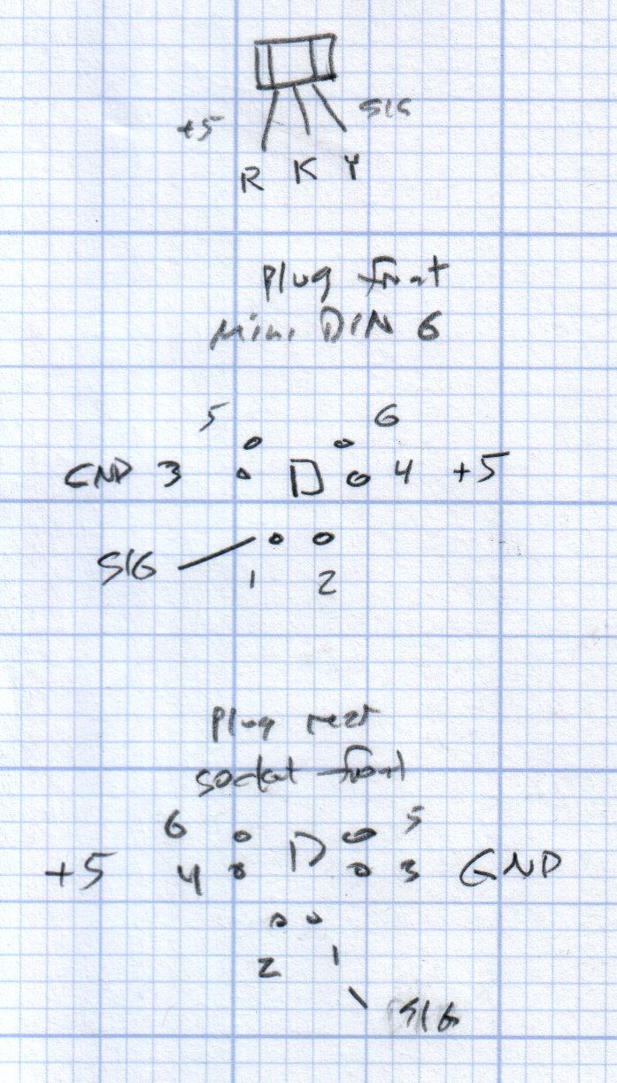
This doodle shows the rudiments of an alternative:
Hall effect distance sensor – original doodle
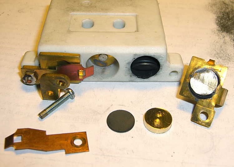
The general idea is to have the existing cross bar / roller move a magnet relative to an analog Hall effect sensor: closer to sensor = higher magnetic field = higher sensor output voltage. Ideally, the magnet provides enough field to max out the sensor just before the pedal reaches the limit of its travel, so the magnet never quite touches the sensor.
An optical wedge would serve a similar function, but this pretty much eliminates all the critical alignment & focusing & friction issues. Plus, I have a bunch of analog Hall effect sensors…
I have a stock of telescoping brass tubing, so the inner tube slides over the 4 mm screw that threads into the existing hardware, replacing the old shaft. That tube slides inside an outer tube that’s aligned in a block attached to the pedal frame; an epoxy blob holds it in position. The inner tube should have a nut on the left end to allow adjusting the rest position.
The Hall effect sensors have a zero-field bias at about VCC/2, so a smaller opposing (and fixed) bias magnet on the far side of the sensor pushes the output voltage to the lower limit. The adjusting screw on that side sets the bias level, if that’s needed.
A spring that’s not shown pushes the cross bar away from the block holding the outer tube and sensor; that’s what restores the magnet to its rest position when the pedal is up.
This being the age of rapid prototyping:
Foot Control Sensor Mount – solid model – top
The bottom view shows an opening for the epoxy blob halfway between the rear wall and the opening for the magnet and Hall effect sensor:
Foot Control Sensor Mount – solid model – bottom
Two bosses inside the pedal base fit into those rectangular cutouts, with the centerline of the tubing at the top of the bosses.
The inner brass tube holds the outer tube in the proper alignment while the epoxy slab cures:
Kenmore 158 – Hall speed control – tubing fit
Fortunately, two of the neodymium magnets in my collection worked out perfectly as the main and bias magnets. The smaller bias magnet just barely saturates the output when epoxied to the back of the sensor and the larger magnet has about 15 mm of active range.
The assembly sequence required half a dozen separate epoxy applications; I used quick-curing clear epoxy, rather than my usual JB Weld, because this isn’t the place for a steel filled epoxy. The final step put a washer on the back of the inner tube to hold the spring in place, with the Hall effect sensor invisible under the wad of closed-cell foam at the bottom:
Kenmore 158 – Hall speed control – epoxy curing
The spring comes from the Big Box o’ Medium Springs, which contains a few more just like it.
That solid model and the OpenSCAD code below include several refinements that don’t appear in the photos. In particular, the graceful slope on the top front will look a whole lot better than the abrasive adjustment required to fit the chunky first version into the pedal case:
Kenmore 158 – Hall speed control – prototype interior
On the other paw, that’s what rapid prototyping is all about. I had no way to measure that dimension, but building one to figure it worked pretty well.
Things that may / will need tweaking:
The centerline of the tubing lies on the same plane as the tops of the bosses under those three screws, but the bosses are not particularly flat. Perhaps some setscrews to fine-tune the height and front-to-back tilt angle?
The sketch had adjustable magnet positions; the as-built hardware doesn’t. It’s not clear they’re needed, although that depends on having exactly the right magnets.
The screws are #4 sheet metal and fit nicely into the metric holes; the original screws held a thin aluminum bracket in place, not that chunky block. I could recess the heads, but …
A 3D printed clamp holding the cable and strain relief bushing in place would be cuter than the sheet metal strap I bashed from scrap.
The far end of the cable terminates in a 6-pin mini-DIN connector, left over from the days when PCs (remember PCs?) had PS/2 mice & keyboards:
Kenmore 158 Improved Speed Control Pedal – cable wiring diagram
I’ll eventually put the emitter resistor into the circuit; these sensors work fine without it. The cable provides electrostatic shielding and I’m hoping the impedance is low enough that the motor won’t induce any noise. In any event, some low-pass filtering won’t slow down the response enough to notice.
Next, some measurements…
The OpenSCAD source code:
// Foot Control Sensor Mount
// Ed Nisley - KE4ZNU - June 2014

Layout = "Show";			// Plate Build Show

//- Extrusion parameters must match reality!
//  Print with 4 shells and 3 solid layers

ThreadThick = 0.20;
ThreadWidth = 0.40;

HoleWindage = 0.2;			// extra clearance

Protrusion = 0.1;			// make holes end cleanly

AlignPinOD = 1.70;			// assembly alignment pins: filament dia

function IntegerMultiple(Size,Unit) = Unit * ceil(Size / Unit);

//----------------------
// Dimensions
// Origin at center front edge of plate
//  Z = bottom surface

PlateSize = [85.0,53.0,15.0];						// overall plate size
MidZ = PlateSize[2]/2;								//  height of spring midline
PlateCornerRadius = 1.5;

FrontBevel = [0.0,15.0,5.5];						// Y from front, Z from centerline

ScrewHolesOC = [[-75.0/2,(37.0 - 14.0/2)],[-75.0/2,(37.0 + 14.0/2)],[75.0/2,37.0]];
ScrewHoleDia = 4.0;									// allow alignment slop around 3 mm / #4 screws

BossSize = [[12.0,28.0],[12.0,27.0]];				// mounting bosses: L R
BossOC = [[-75.0/2,37.0],[75.0/2,37.0]];

Stroke = 15.0;										// foot pedal actuation distance

Bushing = [5.6,23.0];								// outer brass tube
MainMagnet = [10.0,5.0];							// magnet on pushrod
BiasMagnet = [5.0,2.0];								// bias magnet behind Hall effect sensor
Spring = [9.0,8.0];									// recess for pushrod retracting spring
Washer = [10.0,1.0];								// recess for washer atop pushrod

OD = 0;												// subscripts for cylindrical objects
LEN = 1;

SensorThick = 2.0;									// Hall effect sensor on bias magnet
FilletLength = 0.75;								// glue fillet on main magnet

//----------------------
// Useful routines

module PolyCyl(Dia,Height,ForceSides=0) {			// based on nophead's polyholes

  Sides = (ForceSides != 0) ? ForceSides : (ceil(Dia) + 2);

  FixDia = Dia / cos(180/Sides);

  cylinder(r=(FixDia + HoleWindage)/2,
           h=Height,
           $fn=Sides);
}

module ShowPegGrid(Space = 10.0,Size = 1.0) {

  RangeX = floor(100 / Space);
  RangeY = floor(125 / Space);

	for (x=[-RangeX:RangeX])
	  for (y=[-RangeY:RangeY])
		translate([x*Space,y*Space,Size/2])
		  %cube(Size,center=true);

}

//----------------------
// Basic plate shape

module Plate() {

R = PlateCornerRadius;
Px = PlateSize[0]/2 - R;
Py = PlateSize[1] - R;
Sides = 4*4;

BevelAngle = atan2((MidZ - FrontBevel[2]),FrontBevel[1]);

echo("Bevel angle: ",BevelAngle);

	difference() {
		linear_extrude(height = PlateSize[2]) {
			hull() {
				translate([-Px,Py])
					circle(r=R,$fn=Sides);
				translate([Px,Py])
					circle(r=R,$fn=Sides);
				translate([Px,R])
					circle(r=R,$fn=Sides);
				translate([-(20-R),R])			// avoid left front boss
					circle(r=R,$fn=Sides);
				translate([-Px,20+R])			// avoid left front boss
					circle(r=R,$fn=Sides);
			}
		}

		translate([0,0,-Protrusion])						// screw bosses
			linear_extrude(height = (MidZ + Protrusion),convexity=2)
				for (i=[0:1])
					translate(BossOC[i])
						square(BossSize[i],center=true);

		translate([0,0,-Protrusion])						// plate mounting screws
			linear_extrude(height = 2*PlateSize[2] + Protrusion,convexity=3)
				for (i=[0:2])
					translate(ScrewHolesOC[i])
						rotate(180/6)
							circle(d=ScrewHoleDia,$fn=6);

		translate([0,0,MidZ + FrontBevel[2]])		// Front bevel
			rotate([BevelAngle,0,0])
				translate([0,0,PlateSize[2]])
					cube(2*PlateSize,center=true);

	}
}

//----------------------
// Modify plate for position sensor hardware

module Sensor() {

GluePort = [1.5*Bushing[OD],Bushing[OD]/2,PlateSize[2]];	// port for glue anchor around bushing

MagnetPort = [1.5*MainMagnet[OD],
			  (Stroke + MainMagnet[LEN] + FilletLength + SensorThick),
			  (PlateSize[2] + 2*Protrusion)];

	difference() {
		Plate();

		translate([0,(PlateSize[1] - Bushing[LEN] - Protrusion),MidZ])		// bushing
			rotate([-90,0,0])
				cylinder(d=Bushing[OD],h=PlateSize[1],$fn=6);

		translate([-GluePort[0]/2,										// bushing anchor opening
				  (PlateSize[1] - 0.66*Bushing[LEN] - GluePort[1]/2),
				  MidZ - GluePort[2] + Bushing[OD]/2])
			cube(GluePort,center=false);

		translate([0,(PlateSize[1] - Bushing[LEN] - MagnetPort[1]/2),MagnetPort[2]/2 - Protrusion])
			cube(MagnetPort,center=true);

		translate([0,(PlateSize[1] - Bushing[LEN] - MagnetPort[1] + Protrusion),MidZ])
			rotate([90,0,0])
				PolyCyl(BiasMagnet[OD],BiasMagnet[LEN] + Protrusion,6);

		translate([0,(PlateSize[1] + Protrusion),MidZ])
			rotate([90,0,0]) rotate(180/8)
				PolyCyl(Spring[OD],Spring[LEN] + Protrusion,8);

		translate([0,(PlateSize[1] + Protrusion),MidZ])
			rotate([90,0,0]) rotate(180/8)
				PolyCyl(Washer[OD],Washer[LEN] + Protrusion,8);

	}
}

ShowPegGrid();

if (Layout == "Plate") {
	Plate();
}

if (Layout == "Show")
	Sensor();

if (Layout == "Build") {
	translate([0,PlateSize[1]/2,PlateSize[2]])
		rotate([180,0,0])
			Sensor();
}