Ed Nisley's Blog: Shop notes, electronics, firmware, machinery, 3D printing, laser cuttery, and curiosities. Contents: 100% human thinking, 0% AI slop.
Category: Software
General-purpose computers doing something specific
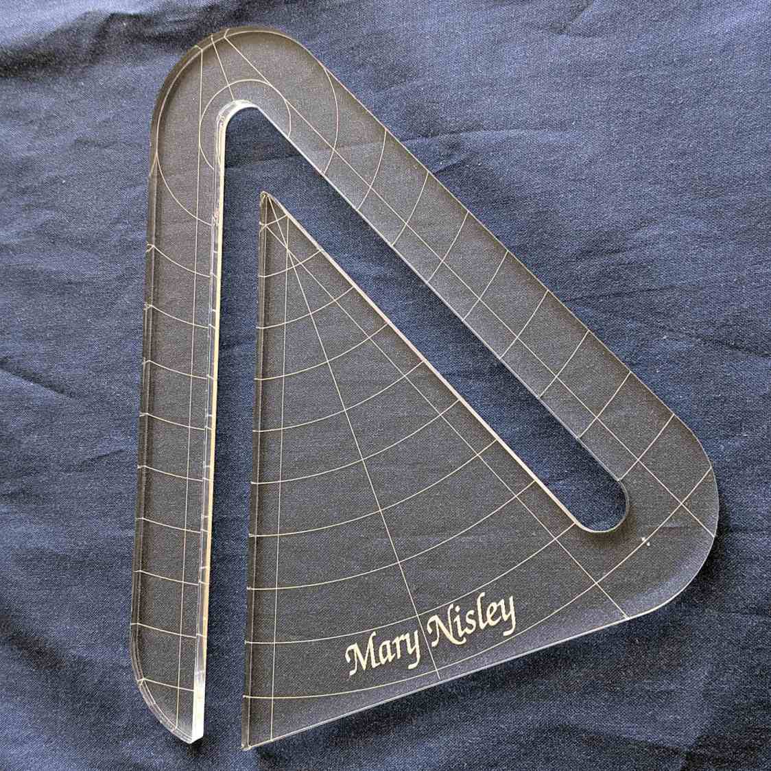
Mary’s current quilt project has a corner design with an essentially infinite number of 45° triangles, which another custom ruler will simplify:
45° Quilting Ruler – finished
That’s the end result of several iterations, proceeding from doodles to sketches to increasingly accurate laser-cut prototypes:
45° Quilting Ruler – prototypes
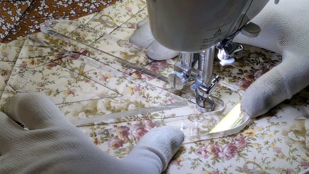
A “ruler” in quilting parlance is a thing guiding the sewing machine’s “ruler foot” across the fabric (or, for sit-down machines, the fabric under the foot) in specific directions:
45° Quilting Ruler – in use
That’s a practice quilt on scrap fabric: quilters need prototypes, too!
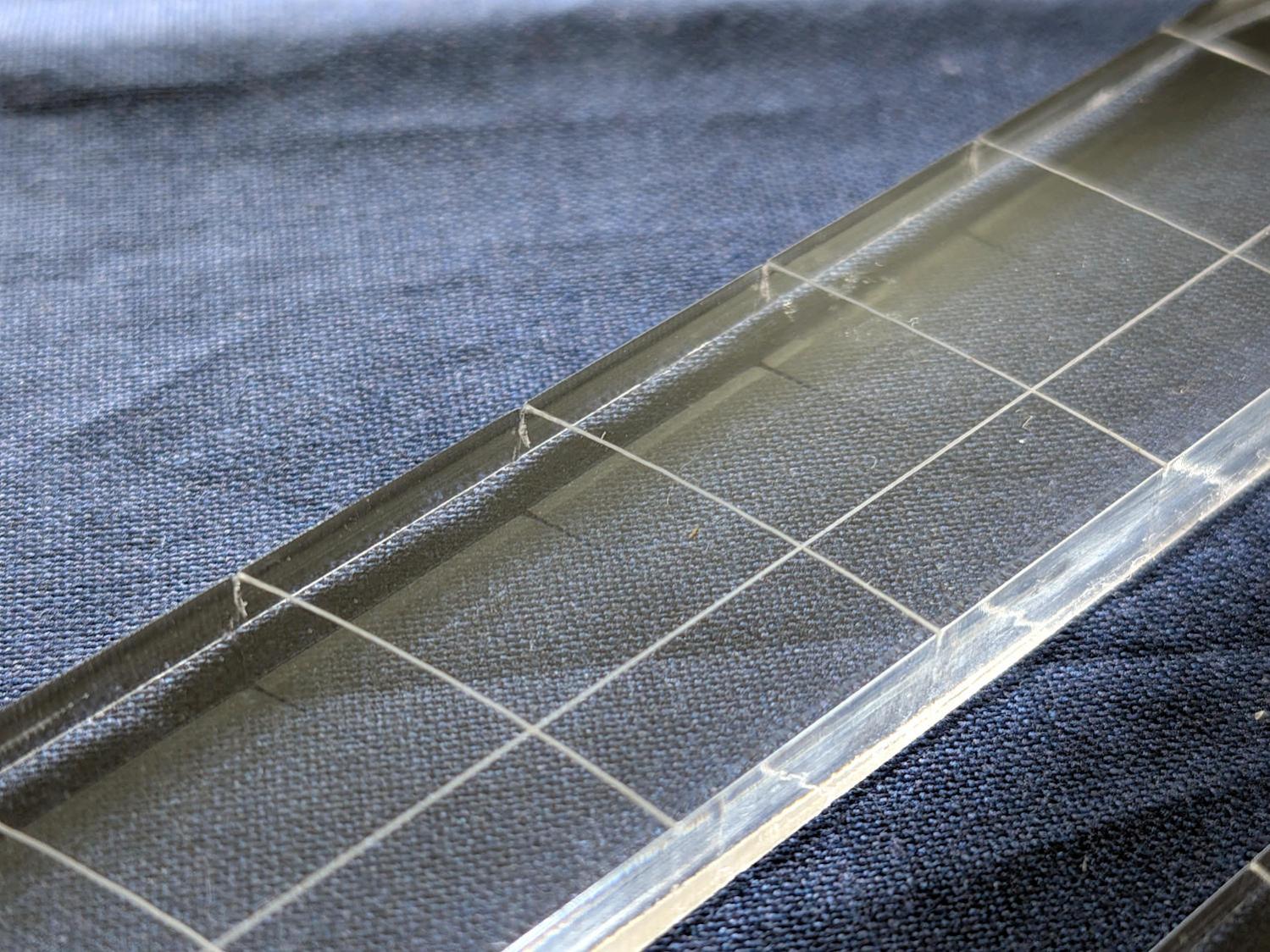
The foot is 0.5 inch OD, within a reasonable tolerance, which accounts for the slot width in the ruler. It’s also intended to run against 1/4 inch thick rulers, which accounts for the thickness of that slab of acrylic.
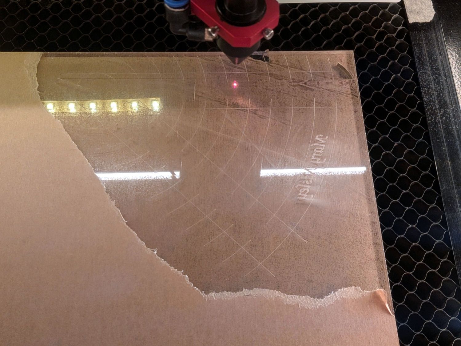
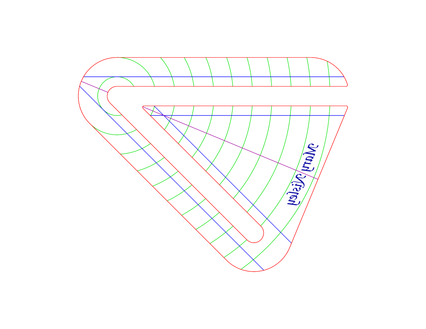
The engraved lines & arcs are on the bottom of the ruler to eliminate parallax errors against the fabric, so the bottom is upward and the text is mirrored for the laser:
45° Quilting Ruler – cutting
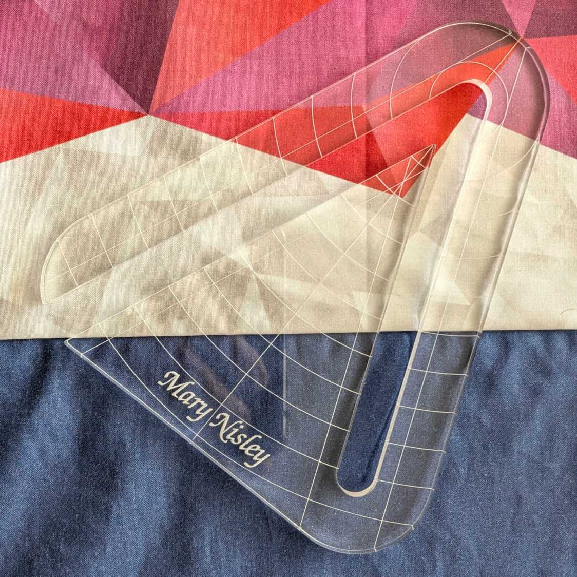
Although fluorescent green acrylic may have higher visibility, clear seems adequate for the fabric in question:
45° Quilting Ruler – colored fabric
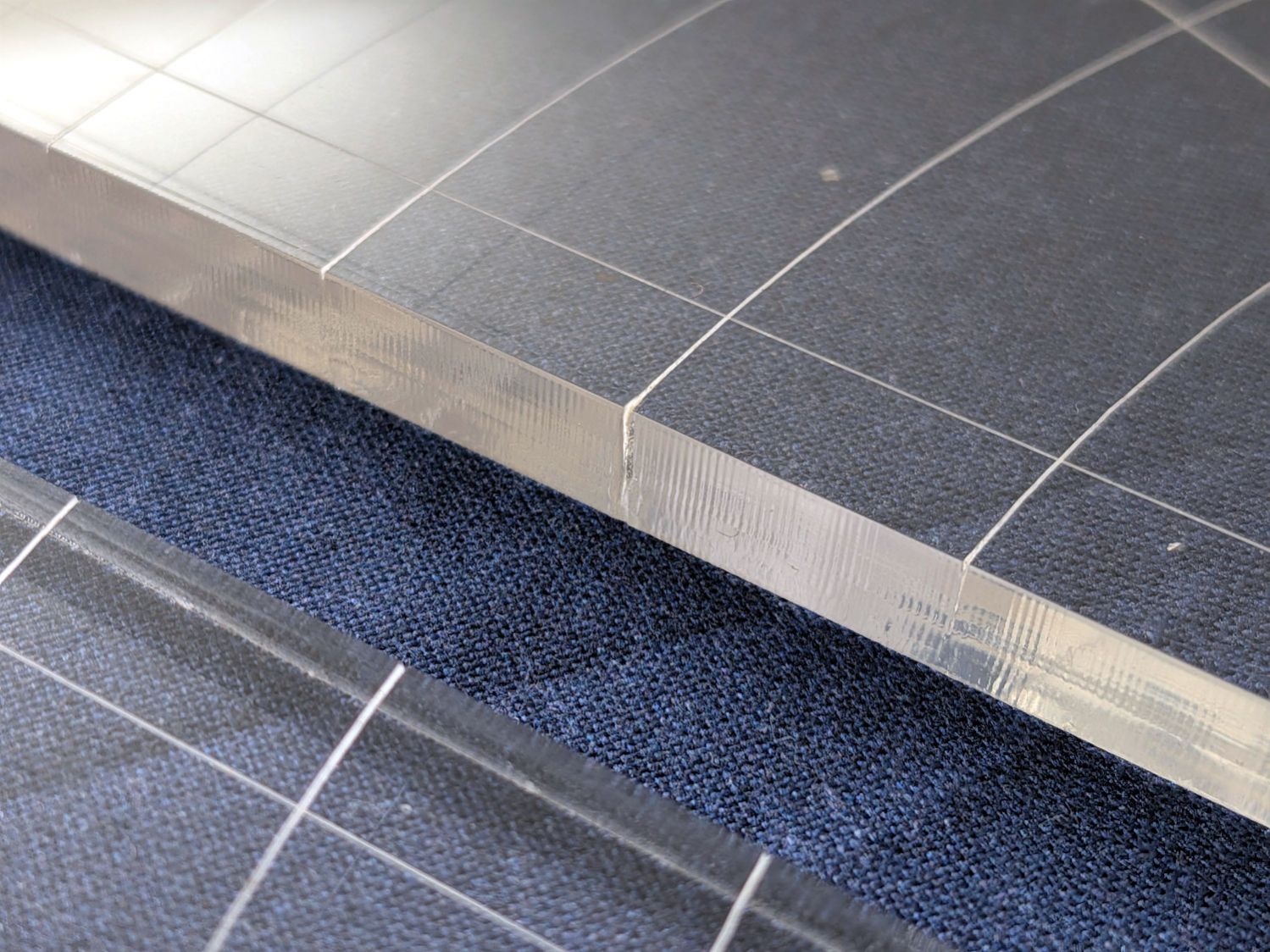
I very carefully trimmed the arcs against the ruler outline using LightBurn’s Cut Shapes, which turned out to be a Bad Idea™, because the high-current pulse as the laser fires causes a visible puncture wound at the still-to-be-cut edge:
45° Quilting Ruler – edge damage
Those are not straight lines and the plastic isn’t bent!
A closer look:
45° Quilting Ruler – edge damage – detail
The arcs without wounds started from their other end and stopped at the edge, which is perfectly fine.
The wounds are unsightly, not structural, but the next time around I’ll extend the markings a millimeter beyond the edges into the scrap material.
The overall design looks busier than it is, because I put different features on different layers in case they needed different settings:
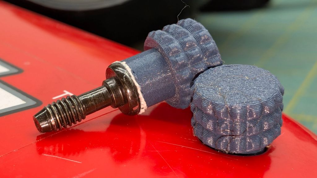
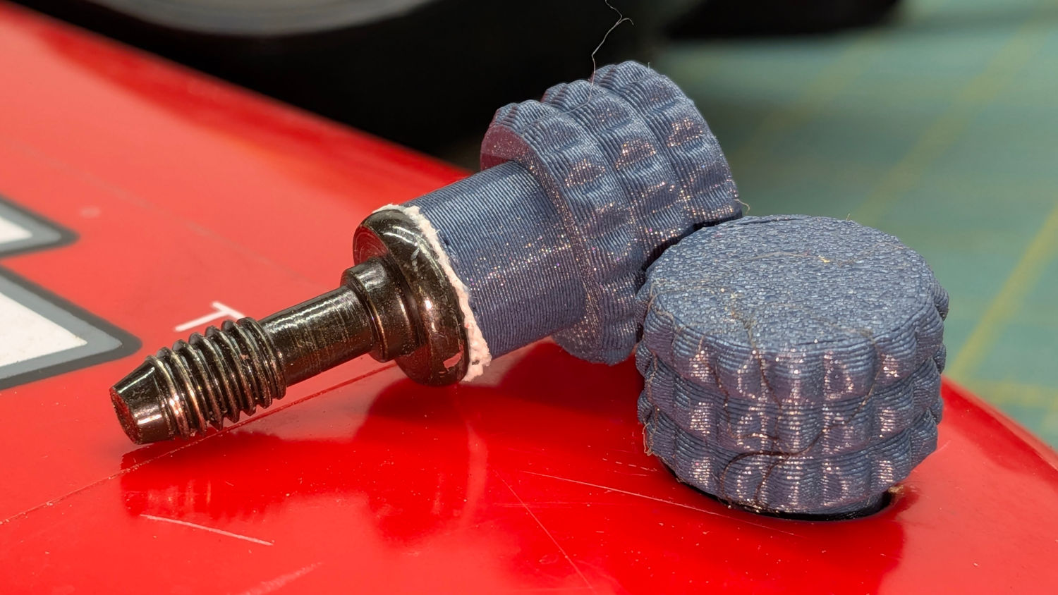
The latches holding the side cover of the portable generator in place work well enough that I never tighten the cover screws, but sometimes one will vibrate itself into place and require less than one turn of a screwdriver to release. Given that I put a knob on the air filter screw, a pair of knobs on the side cover screws makes sense:
Generator Cover Screw Knob – installed
Those are custom screws! The narrow neck keeps them captive in the cover, which is a Good Thing™.
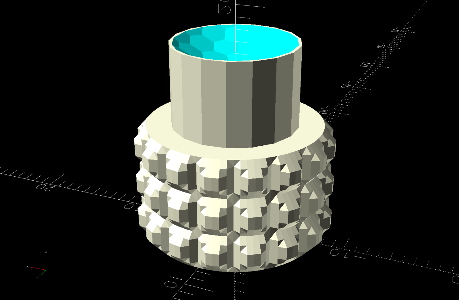
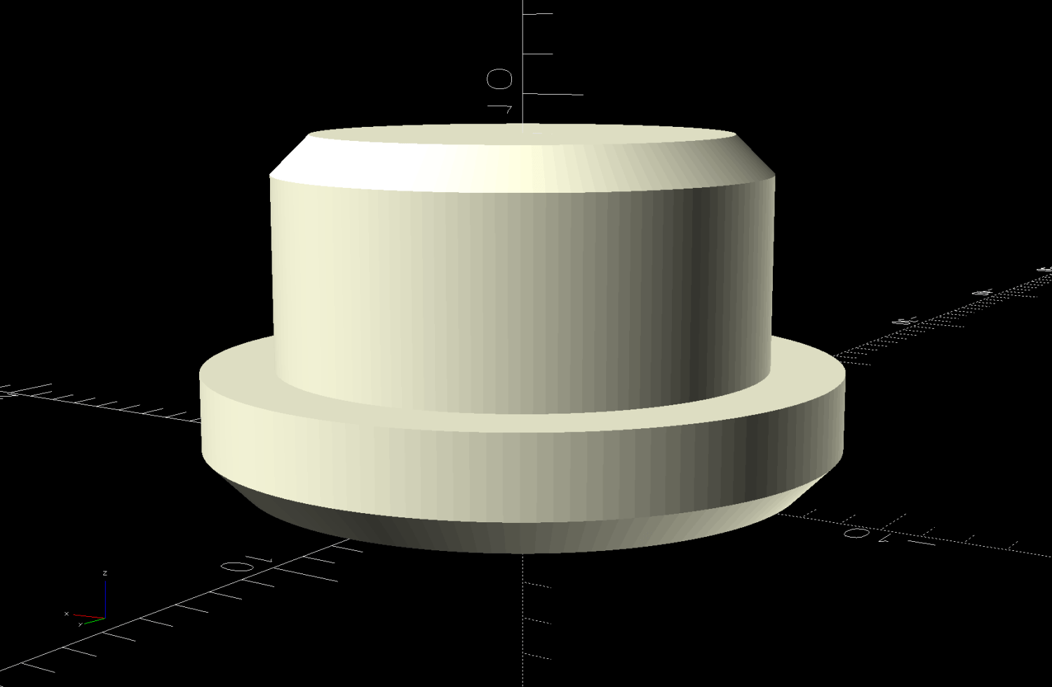
These knobs obviously descend from the air filter knob, with less knurling and a short shaft to clear the recess in the cover:
Generator Cover Screw Knob – solid model
Unlike the air filter knob, the double-sided tape gluing these to their screws isn’t continually compressed, so the knobs may eventually shake off. Should that happen, I’ll deploy epoxy.
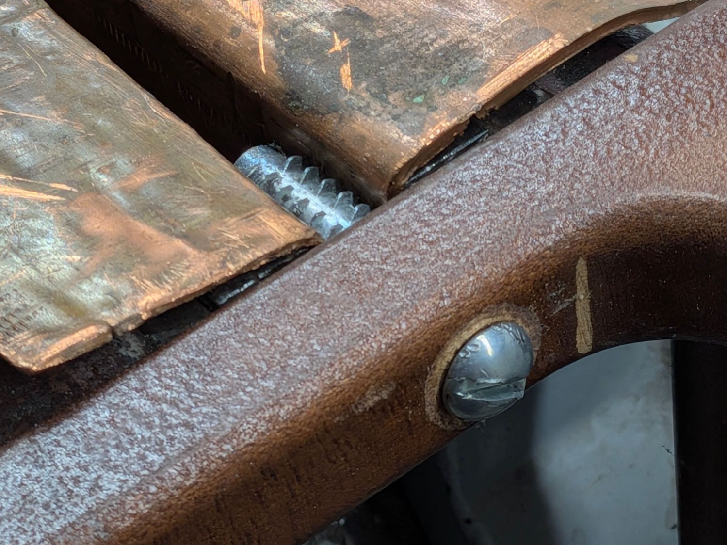
A clothes rack Mary intended use with some work-in-progress quilts seemed entirely too wobbly for the purpose, so I tried tightening its screws. This did not go well, as some of the threaded inserts sunk into the vertical bars spun freely and, with a bit of persuasion, pulled straight out of their sockets:
The reddish fluid is Kroil penetrating oil I hoped would free the screws from the corrosion locking them into the inserts. After an overnight soak, they still required force majeure:
Clothes rack screws – threaded insert in vise
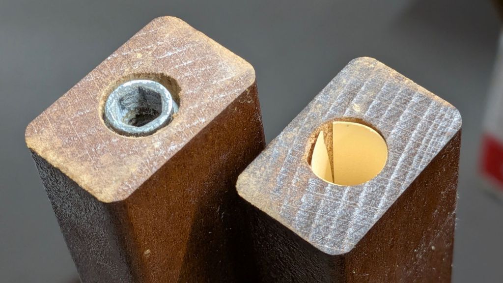
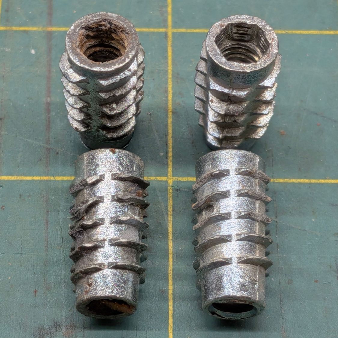
The two inserts on the left came from the top of the rack and the other two from the bottom:
Clothes rack screws – threaded insert corrosion
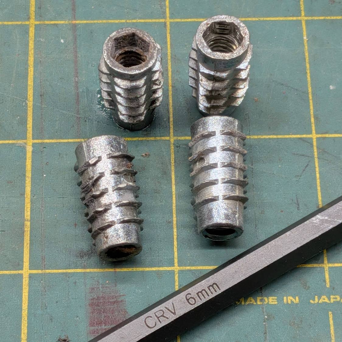
Similar inserts have a hex drive recess and, because these are for 1/4-20 screws, I expected an inch size hex key. Nope, they want a hard metric 6 mm:
Clothes rack screws – threaded insert reformed
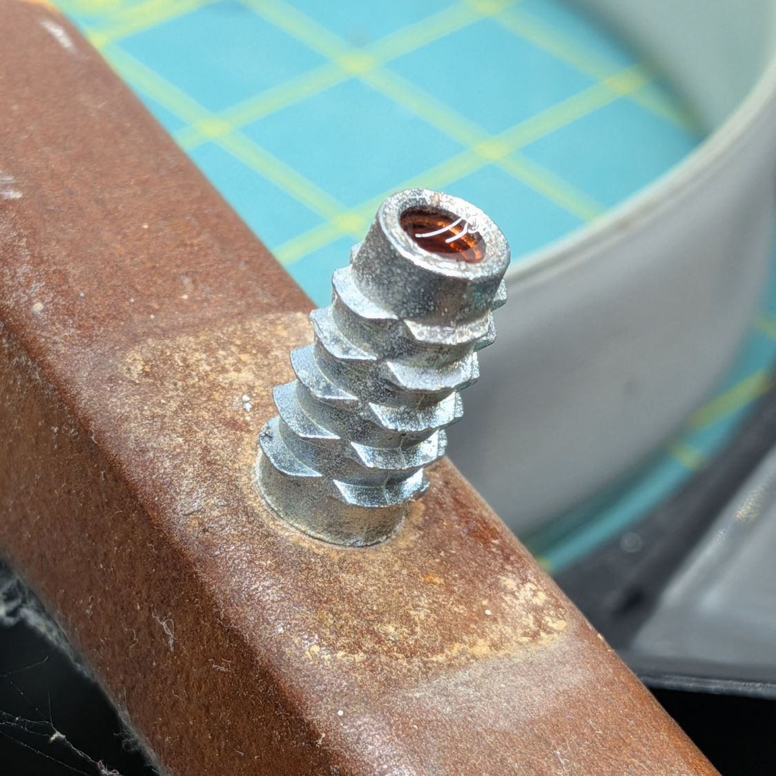
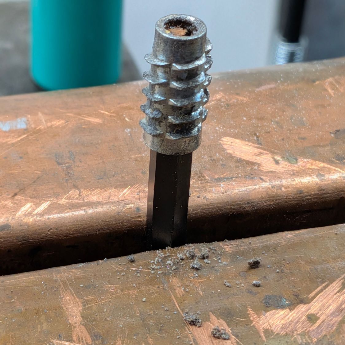
I cleaned up the corroded inserts by the simple expedient of tapping them firmly onto the 6 mm wrench held in the vise:
The crud around the bottom fell out of previous contestants during their reformation.
I considered epoxying the inserts in place, but settled for tucking a thick paper shim into each hole:
Clothes rack screws – threaded insert shim
They’re entirely snug right now and, should they work loose, I’ll coat the hole with epoxy, roll up another shim, screw the insert in place, await curing, then declare victory and hope nobody must ever remove them.
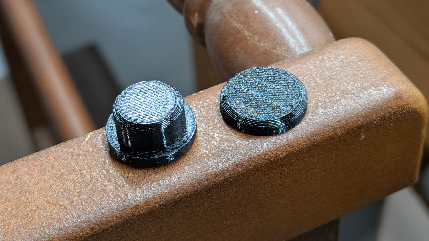
The 1/4-20 screws in the top member sit deep in recesses that surely had decorative wood plugs when the rack left the factory. Alas, they’re long gone, which may have let water / moisture corrode the screws + inserts . I’m not much good for “decorative” items, so this must suffice:
Clothes Rack Screw Covers – solid model
A snippet of double-sided tape on one side of the hole keeps them in place:
Clothes rack screws – cover installed
They look better in person …
The trivial OpenSCAD source code:
// Clothes rack screw cover
// Ed Nisley - KE4ZNU
// 2026-03-13

include <BOSL2/std.scad>

/* [Hidden] */

NumSides = 4*3*3*4;
$fn=NumSides;

//----------
// Build it
//  … with magic numbers from the rack

cyl(3.0,d=16.7,chamfer1=1.0,anchor=BOTTOM) position(TOP)
  cyl(6.0,d=12.9,chamfer2=1.0,anchor=BOTTOM);
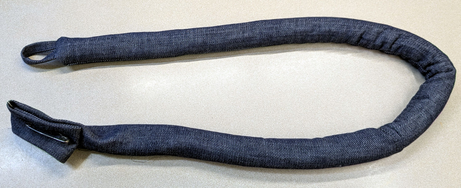
Mary made a frame weight to maintain tension on the fabric in the HQ Sixteen longarm:
Longarm fabric frame weight
It’s a sturdy cloth tube filled with BBs, somewhat like a grossly overweight door snake (a.k.a. draft stopper).
The bottle of 6000 copper-plated steel BBs arrived in an overwrap bag of the sort Amazon applies to all bottled products. This was a Good Thing, because the scrap of packing paper did nothing to cushion the bottle in an otherwise empty box. The bag contained most of the shattered cap and a few BBs, with escapees rattling around inside the box and surely a few left along the way.
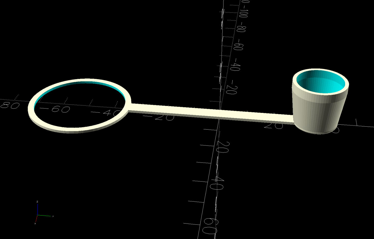
So I conjured a replacement cap from TPU:
Crosman BB bottle cap – solid model – build view
It fits around the bottle neck and snaps onto the spout just like the original:
Crosman BB bottle cap
Except this one is unbreakable.
The strapless TPU cap was a quick test to verify the fiddly shoulder snapping onto the bottle snout:
Crosman BB bottle cap – solid model – section view
As it turned out, we poured all 6000 BBs (minus those few lost-in-transit strays) into the cloth tube, but the bottle will come in handy for something someday.
This file contains hidden or bidirectional Unicode text that may be interpreted or compiled differently than what appears below. To review, open the file in an editor that reveals hidden Unicode characters.
Learn more about bidirectional Unicode characters
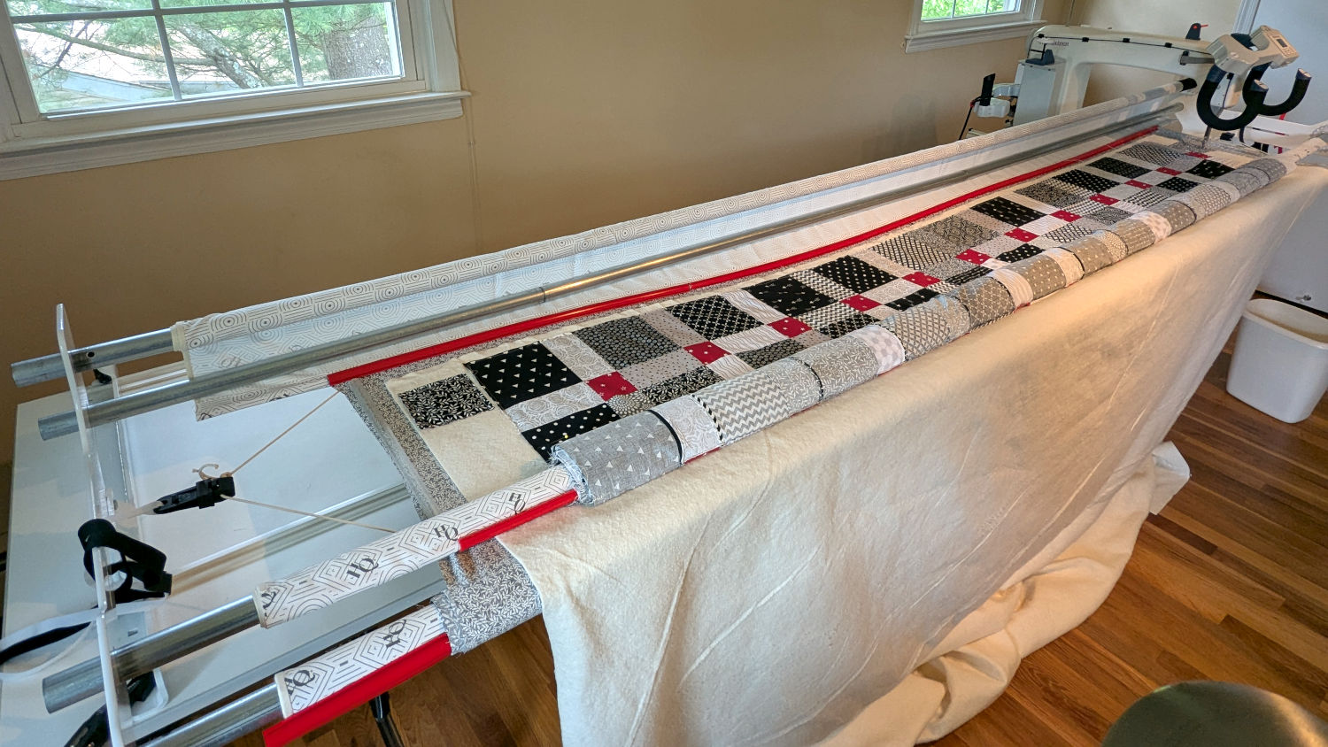
The rods (a.k.a. tubes or poles) holding & guiding the quilt top / batting / backing fabric on Mary’s HQ Sixteen longarm quilting machine span the eleven feet of the table:
HQ Sixteen – table overview
The two end plates are 1/4 inch steel plate with four punched holes for the rods / tubes, which look remarkably like EMT. The machine is two decades old and Mary is (at least) the third owner, so it’s no surprise the rods long ago wore through the white powder-coat paint on the plates and, during the course of a long quilting project, now deposit black dust on the table.
Black dust not being tolerable near a quilt-in-progress, Mary asked for an improvement.
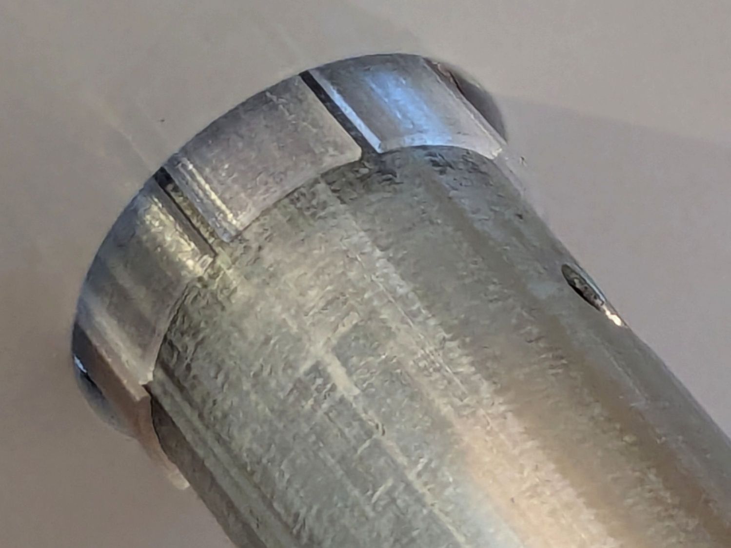
The tube OD is 28.7 mm (so it’s probably 1 inch EMT) and the plate hole ID is 31.2 mm (likely a scant 1-¼ inch punch), leaving barely a millimeter of clearance all around. I wanted to make a bearing from suitably slippery Delrin / acetal, but figured 3D printed PETG would suffice for at least while.
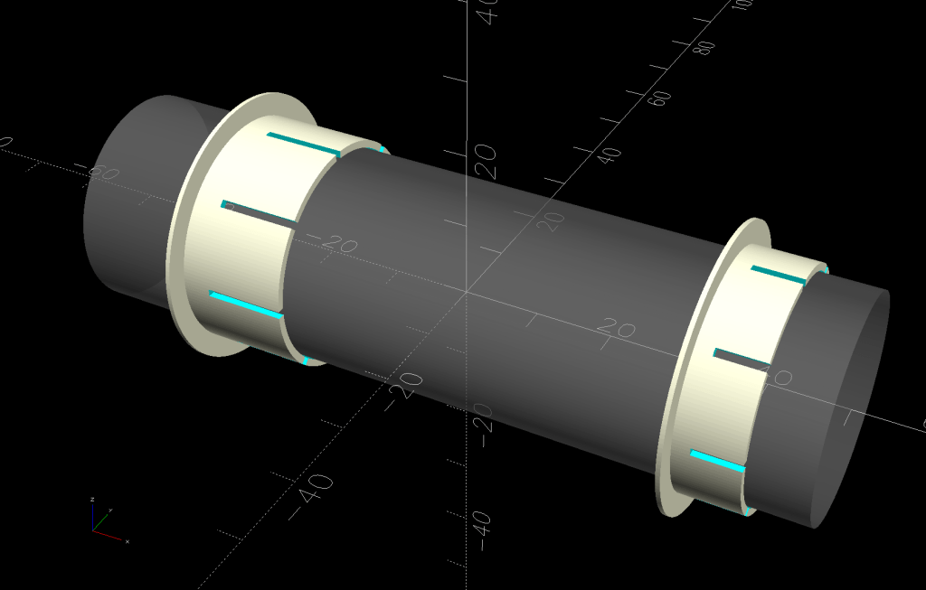
The proper term is “bushing“, because it has no moving parts:
Rod Bearing Sleeve – solid model – show view
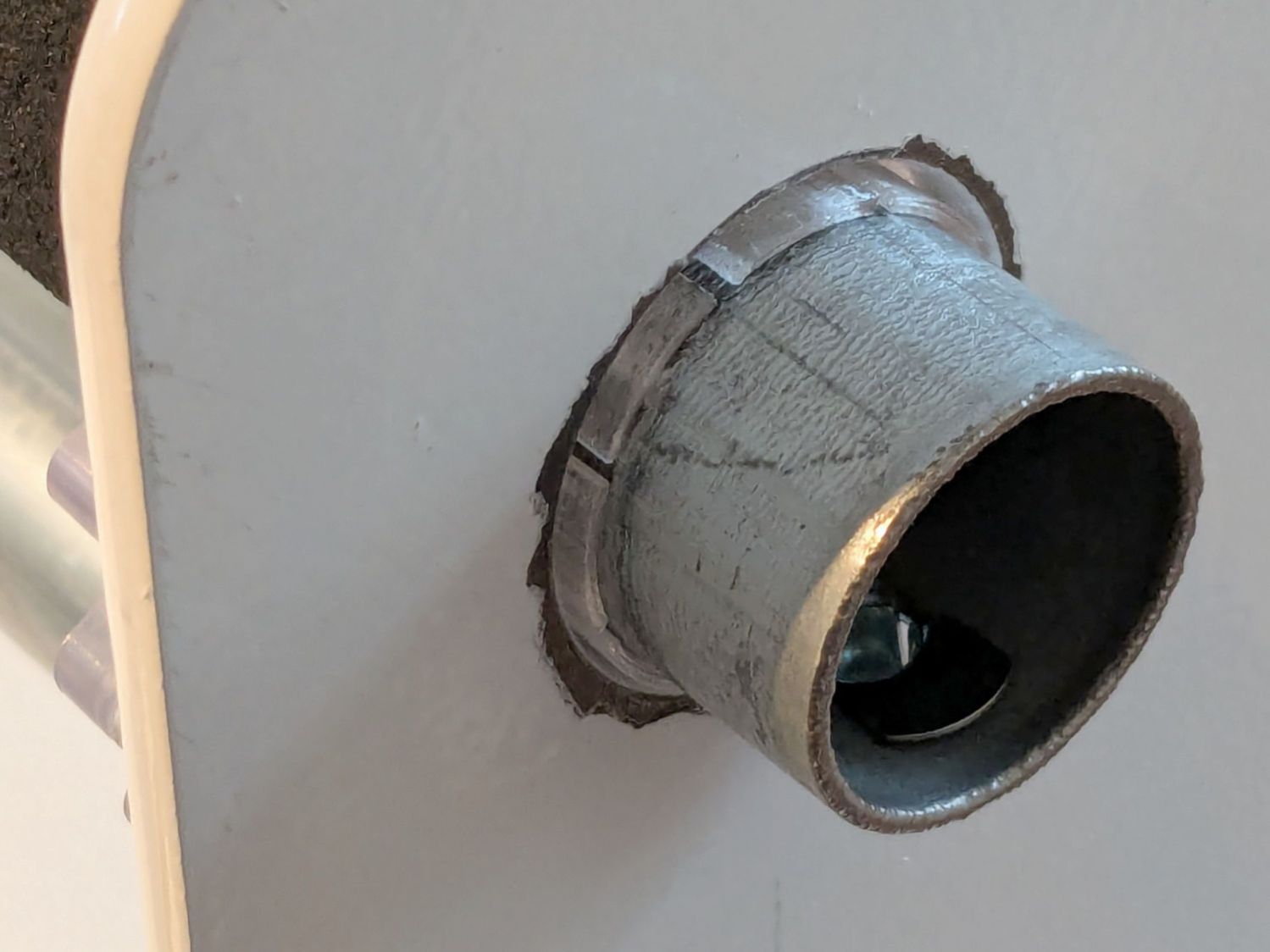
On the right side, the bushing rim must fit between the sprockets and the plate:
HQ Sixteen rod – right front
The spring-loaded pin holding the tube in place (visible on the inside bottom) sets the maximum length:
HQ Sixteen rod – right outer
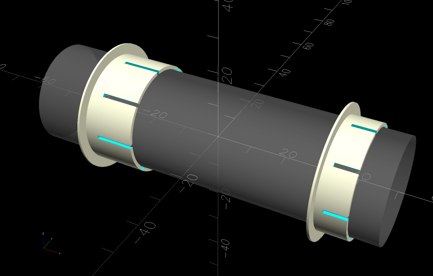
The left side has none of that, so I made the bushings a little longer:
HQ Sixteen rod – left inner
The left-side bushings will need a better design should normal back-and-forth sliding push them out of place.
A touch of silicone grease around the plate holes makes those bushings / bearings turn sooo smooth.
This file contains hidden or bidirectional Unicode text that may be interpreted or compiled differently than what appears below. To review, open the file in an editor that reveals hidden Unicode characters.
Learn more about bidirectional Unicode characters
The gotcha lies in Step 3, which requires mousing & clicking through a tedious file selection dialog. For whatever reason, Windows / LightBurn does not remember your place in the file directory, so you must not only remember which card you just punched, but maneuver to the next card in the sequence.
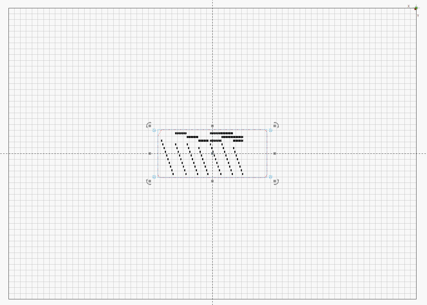
It turns out there exists a lightly documentedSendUDP.exe command-line program to send a file to the running LightBurn instance, which will (in the case of an SVG file) import it and center the layout at the middle of the workspace.
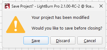
Which means a Windows batch file can feed SVG files, one at a time, in order, to LightBurn. Before importing the file, however, LightBurn verifies you want to blow away the previous layout:
LightBurn – Confirm import
Tapping D lets the import proceed.
The feed-lb.bat batch file:
@echo off
for %%f in (%1) do (
    echo Sending: %%f
    "c:\Program Files\LightBurn_Prerelease\sendudp" "%CD%\%%f"
    pause
)
echo Done!
Because the SVG files have convenient sequential names, this does what’s needed:
…snippage…>.\feed-lb.bat Cards\Tests\test-?-lb.svg
Sending: Cards\Tests\test-1-lb.svg
Press any key to continue . . .
Sending: Cards\Tests\test-2-lb.svg
Press any key to continue . . .
Set up the process:
Start LightBurn with the proper layer defaults
Start a Command Prompt
Get to the proper directory
Run feed-lb.bat aimed at the SVG files
Align the first card
Click in LightBurn window
Alt-S to start cutting
When the cutting is done, the loop continues:
Replace / align card
Click the Command Prompt window
Hit (almost) any key to send the next file
Click the LightBurn window
D to discard old layout / import next SVG
Alt-S to start cutting
Iterate
Assuming you don’t spend too much time aligning a card, punching it can take up to four minutes. This process is definitely not competitive with an experienced operator on a real IBM 029 keypunch machine, but it’s as good as it gets in the Basement Shop.
One wrinkle: The imported SVG file uses LightBurn layer colors, so the various shapes appear on those layers with their default speed / power cut settings. It’s your responsibility to make the cut setting defaults match the cardstock, because that’s the only way (short of per-card clicking) to make it happen.
Another wrinkle: the Command Prompt window opens at your Windows home directory, thus requiring a little setdir.bat file in there to get you where you want to go:
@echo off
z:
cd "\Project Files\Laser Cutter\Punched Cards\Programs\"
dir
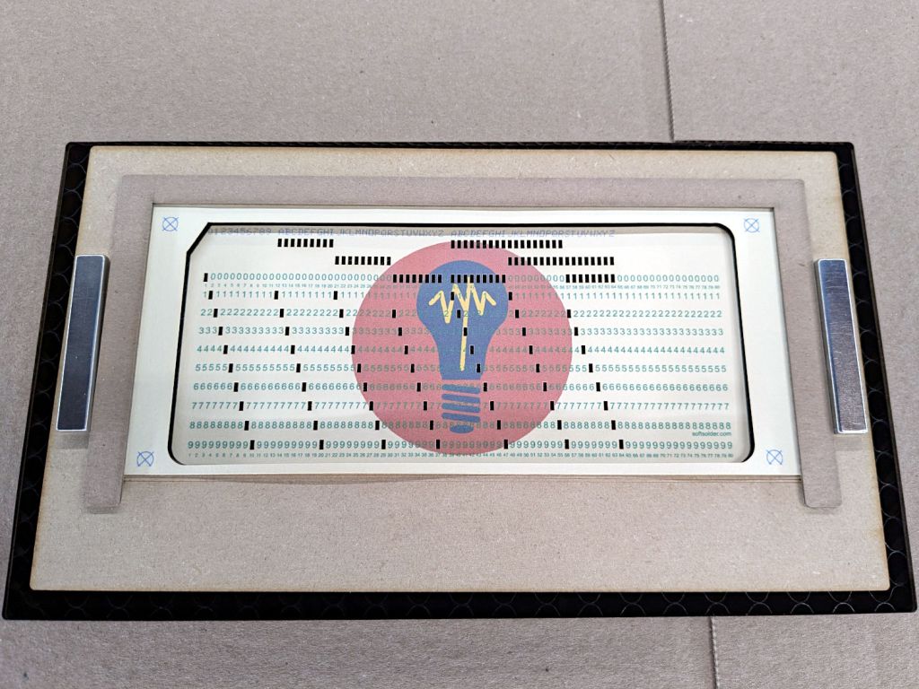
Now it’s just a matter of punching and stacking cards:
Punched cards – storage trays
It’ll take a while before I’m ready for the next step …
The 1/3 Letter sheets aren’t exactly (11 inch)/3 tall, because neither the paper cutter nor my cutting hand have any particular accuracy
The printer’s feed rollers don’t maintain the sheet’s angular or positional alignment as it travels through the printer
A fractional-millimeter misalignment between the printed characters and the evaporated holes is obvious
Performing an intricate alignment dance on each card guarantees at least an occasional misstep
I initially thought “Well, of course, I’ll just use LightBurn’s Print and Cut tool to match them up.” After some fumbling around, PnC is entirely too heavyweight for the problem at hand and a much simpler / faster / easier technique works better.
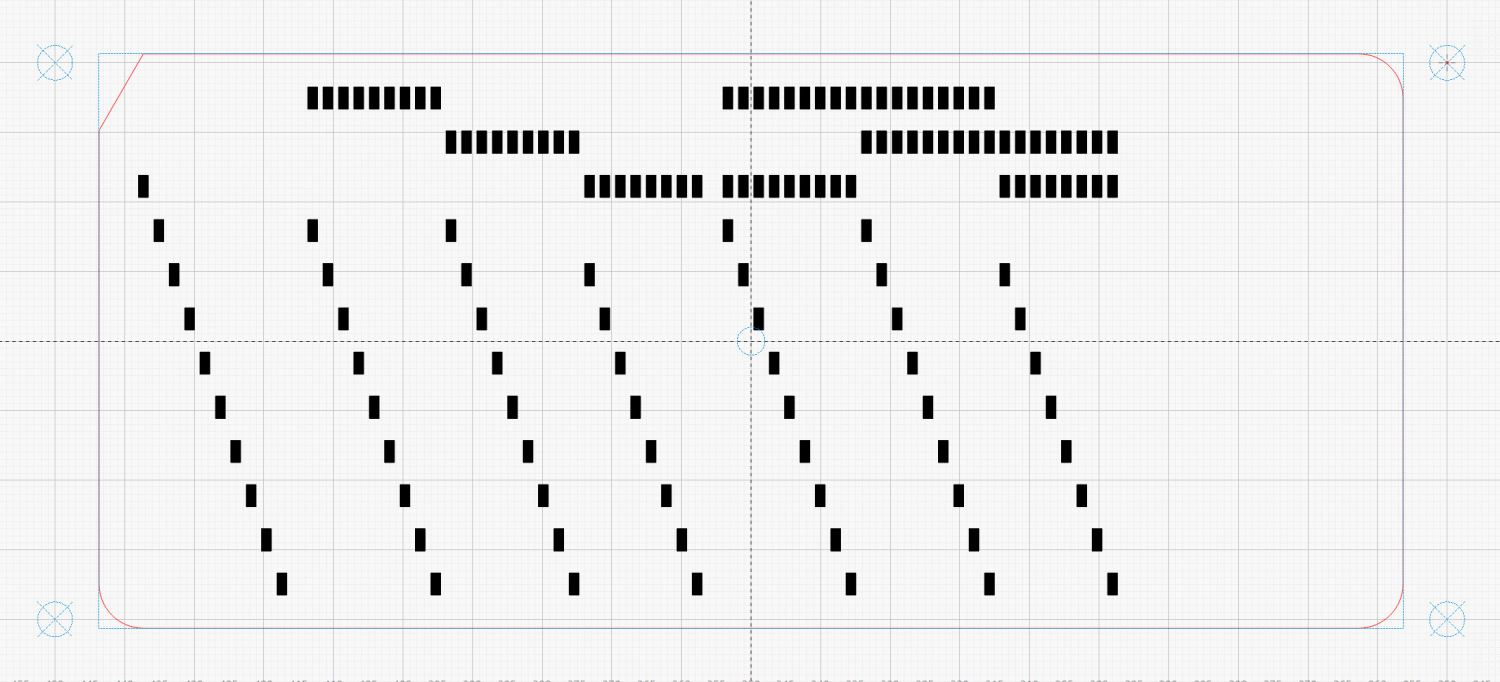
It turns out LightBurn imports SVG files centered on the layout grid representing the laser platform:
LightBurn – imported SVG layout
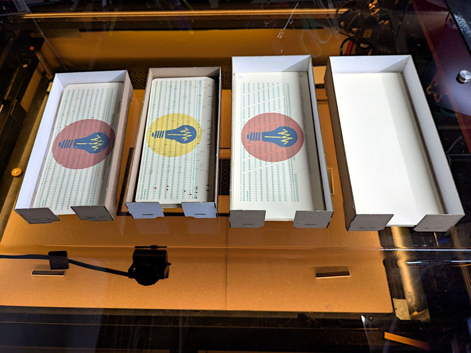
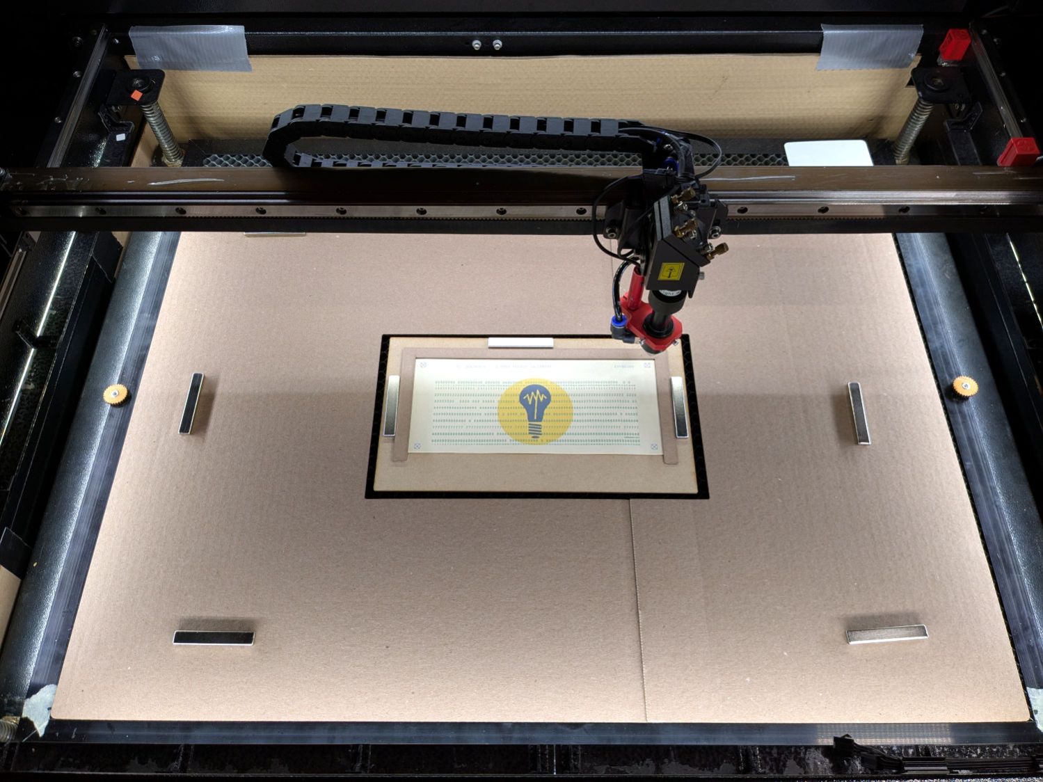
So putting the card fixture dead-center on the platform lines them up pretty closely:
Punched cards – laser fixture overview
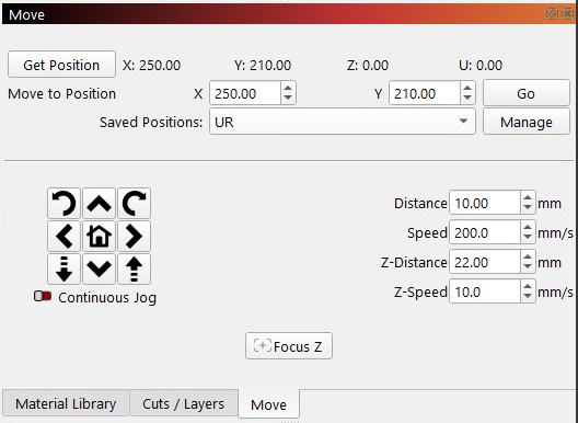
After importing an SVG, use Move Laser to Selection to put it in the middle of the upper right target, then create a Saved Position imaginatively called UR:
LightBurn – Move window UR position
Repeat for the lower left target to create the LL position.
Because the targets are on 200×80 mm centers and the middle of the platform is at (350,250), the target positions will be nice round numbers:
UR = (250,210)
LL = (450,290)
Yes, the coordinates run backwards, because that’s how Ruida controllers deal with a home position in the rear right corner of the platform.
You define those positions once, because all the cards are the same size and end up in the same location on the platform.
Although I expected to slide the cards under the fixture’s retaining lip from the front, it turns out an easier way is:
Gently buckle the card center upward
Align it against the rear edge
Slide the left edge under its lip
Lower the center while sliding the right edge under its lip
Tuck the card under the rear lip
Verify the front edge aligns with the marked lines, which means it’s properly in the fixture
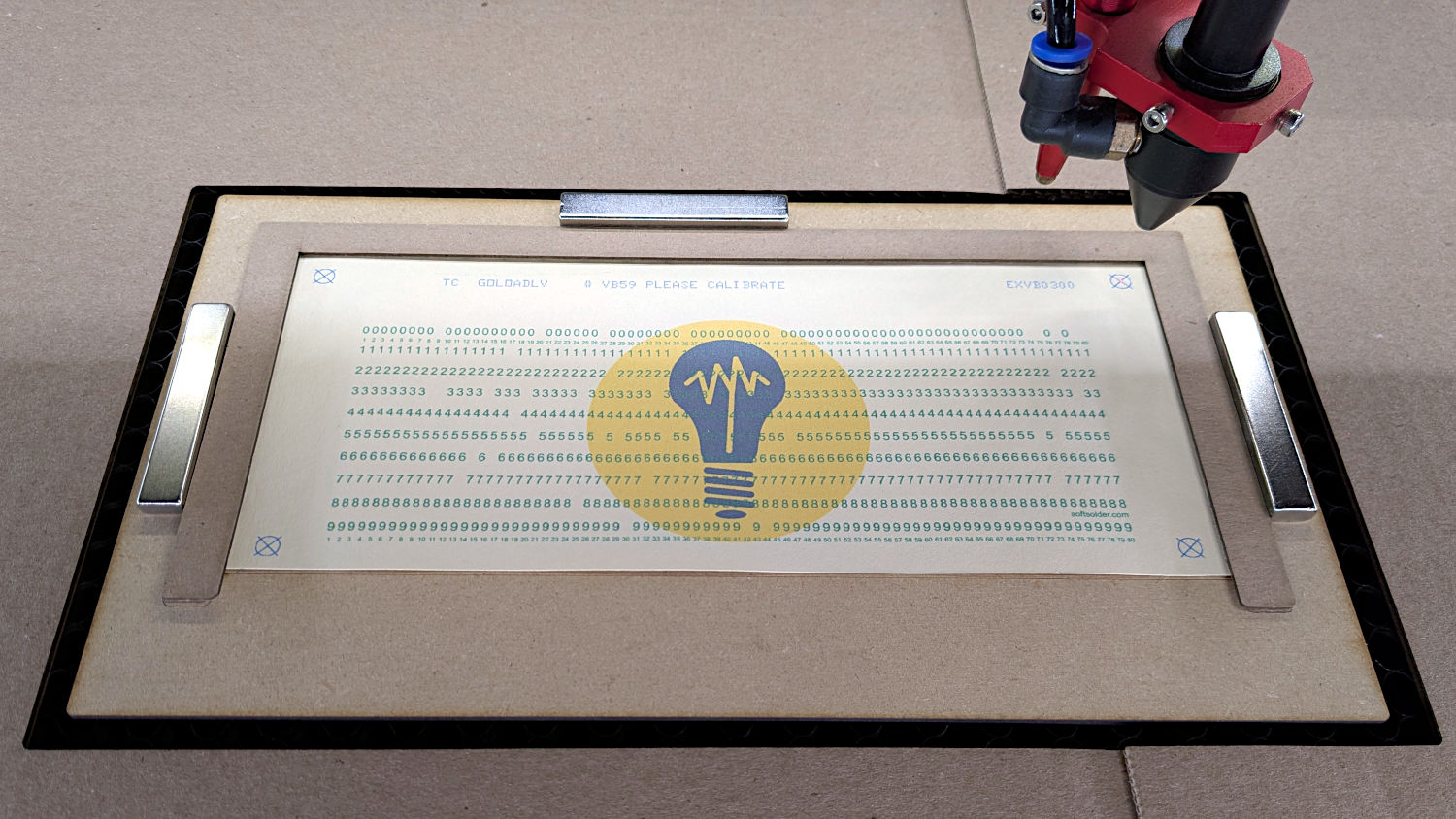
The magnets hold the fixture against the honeycomb:
Punched cards – laser fixture alignment
The fixture can still slide with firm finger pressure and the card can move a little bit within the fixture. Note that leaning on the honeycomb will press it (and the fixture) downward enough to put the dot at a slightly different position; if you align while leaning, recheck the dot’s position after you unlean.
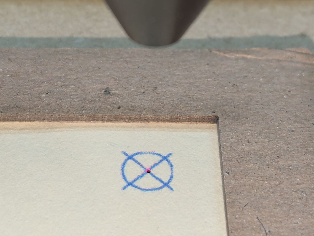
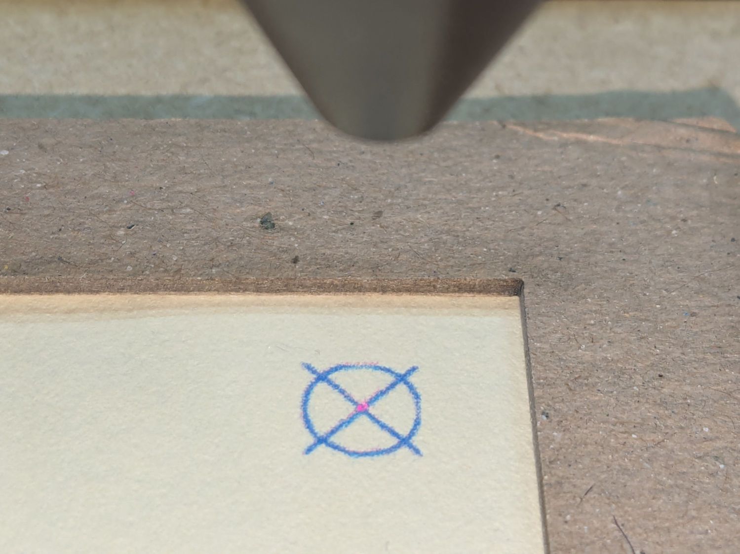
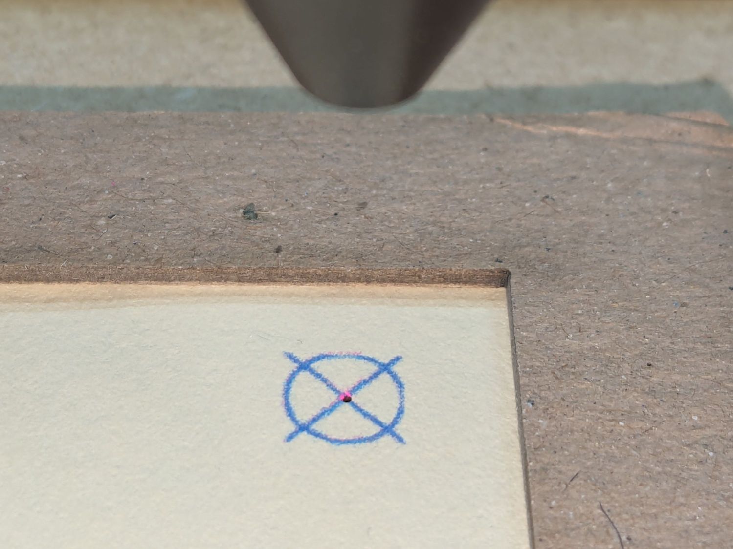
Move the laser to the UR position and skooch the fixture to align the upper right target to the red dot:
Red dot vs printed target alignment
The blue lines are nominally 0.2 mm wide and actually about 0.3 mm wide, so the red dot is 0.3 mm diameter. If your red dot is larger, better focus and a polarizing filter will help.
I periodically fire a test pulse to verify the red dot matches the actual laser beam position:
Red dot vs printed target vs laser spot alignment
That slight mismatch adds to the overall positioning error.
Repeat for the LL target, recheck UR to make sure it didn’t move, iterate as needed.
The printed card is now aligned to the hole pattern about to be burned into it.
Although this sounds like a lot of faffing, it goes surprisingly quickly because all the cards are Pretty Close™ to identical and the adjustments are very small. Although it’s possible to park the laser head at the UR position, I prefer to have it out of the way while unloading & loading the cards, then move it directly to UR to check the new card.
Fire The Laser:
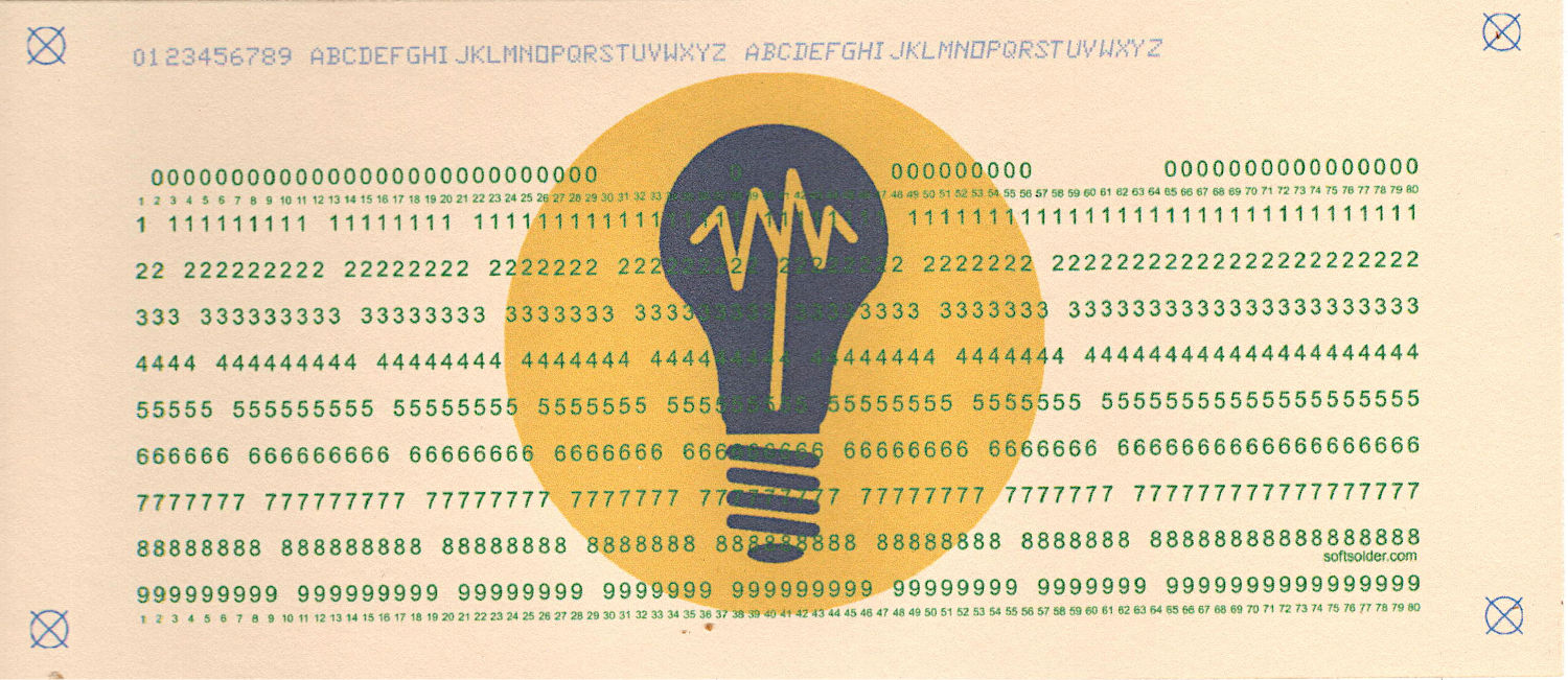
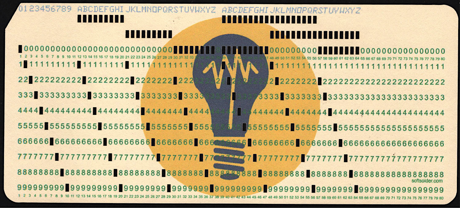
Test Card 3 – punched
I love it when a plan comes together:
Test Card 3 – punched – detail
A dash of automation helps when doing more than one card, which, believe it or not, involves a Windows batch file …


