Ed Nisley's Blog: Shop notes, electronics, firmware, machinery, 3D printing, laser cuttery, and curiosities. Contents: 100% human thinking, 0% AI slop.
Category: Science
If you measure something often enough, it becomes science
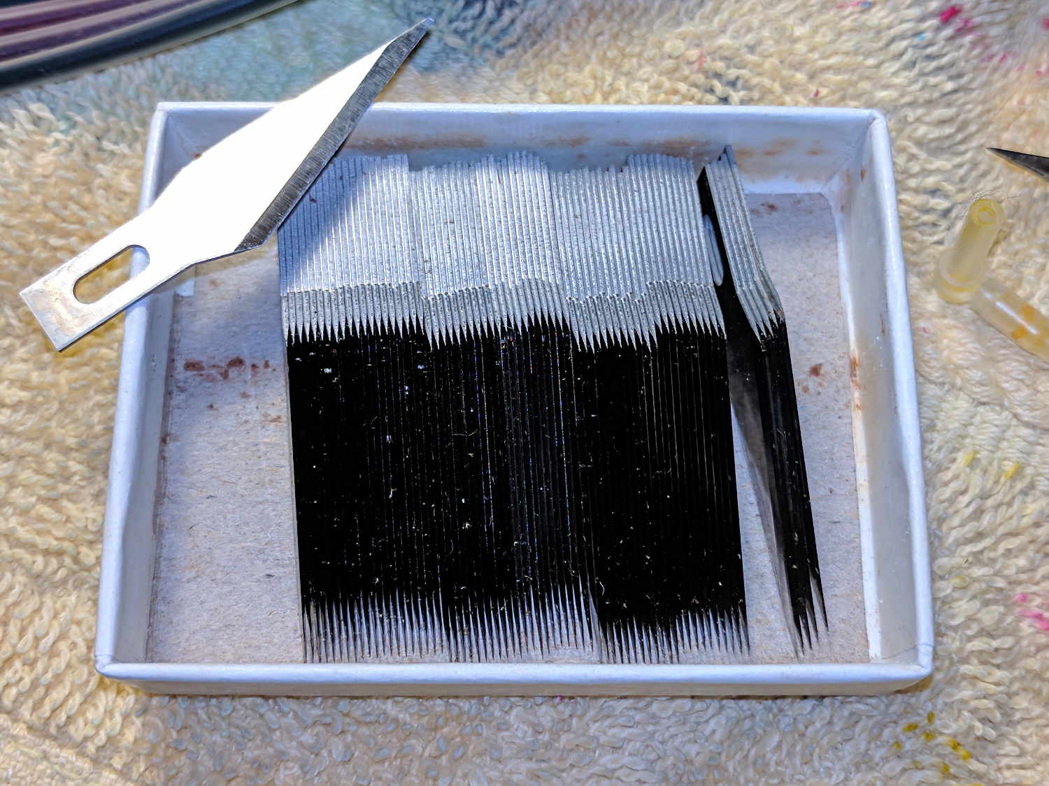
The best way to get a pure, non-reflective black uses optics, not pigments:
Matte black blade edges
The shiny steel blades reflect light just fine, but the reflections have no way back out of the gap between adjacent edges: the angle of reflection always points away from you and the incoming light.
I always admire the blackness when I open that box.
Yes, I’m a member of the Society of the Easily Amused.
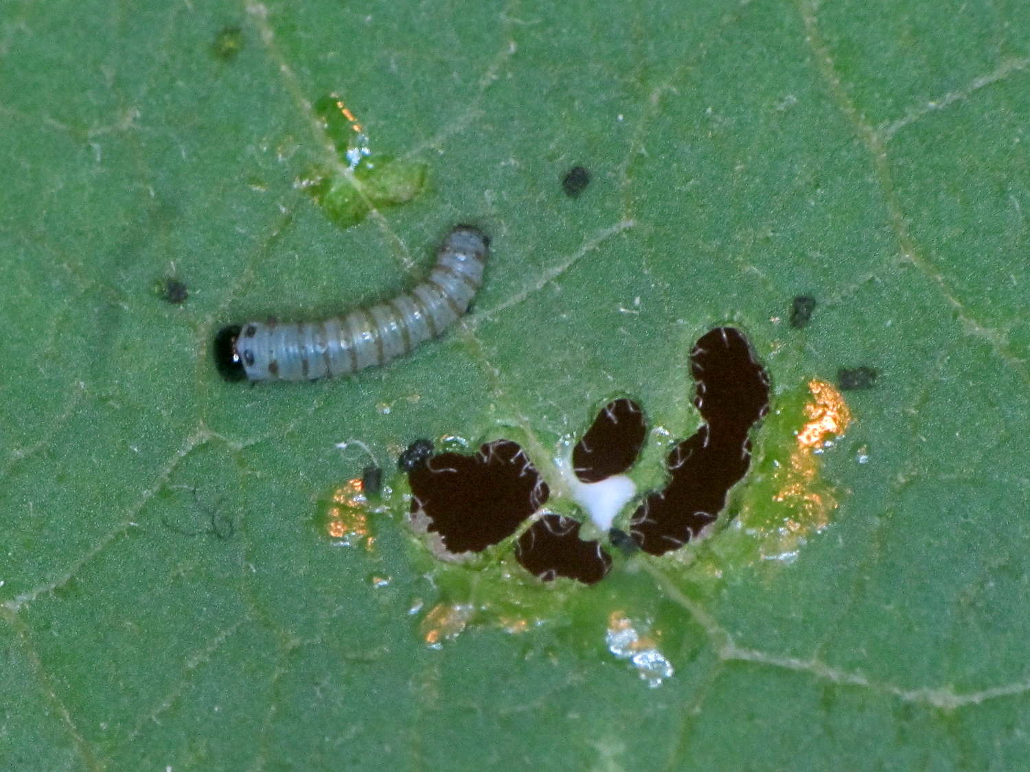
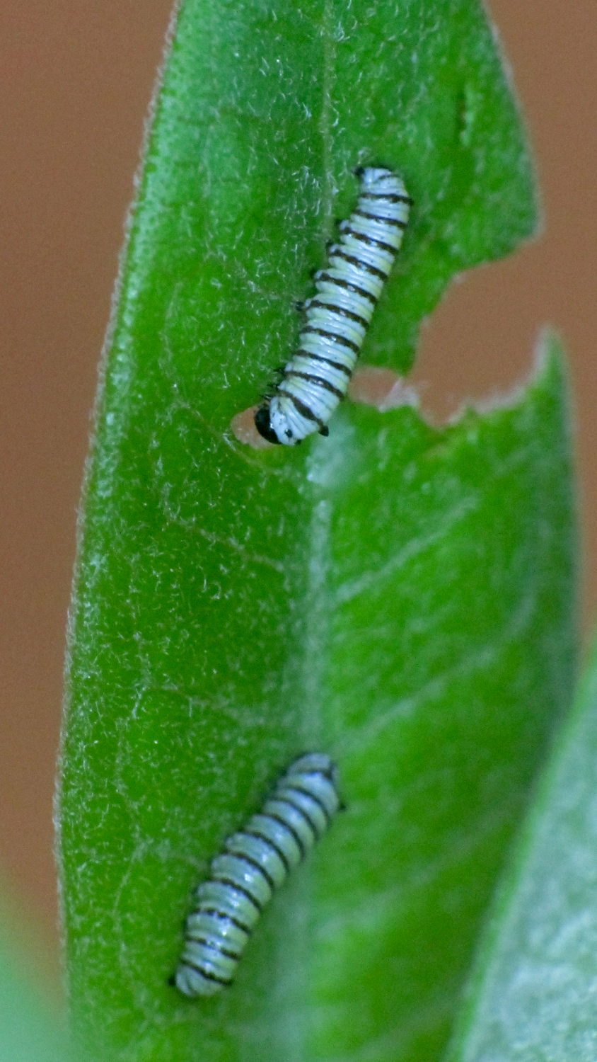
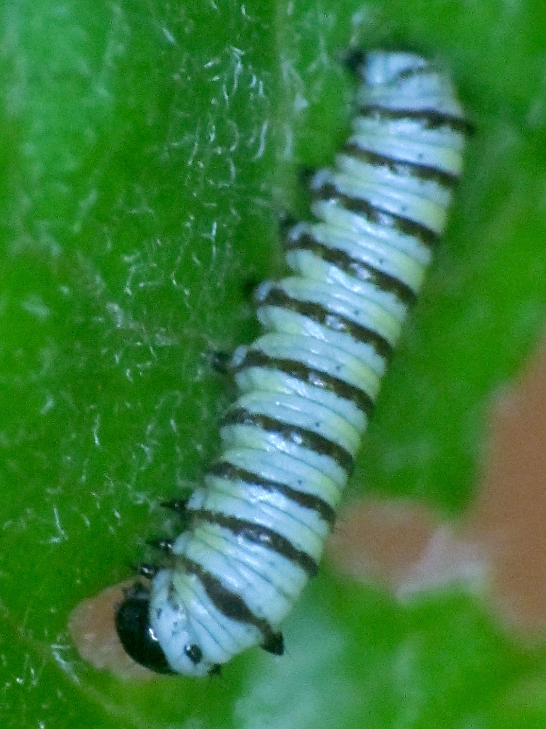
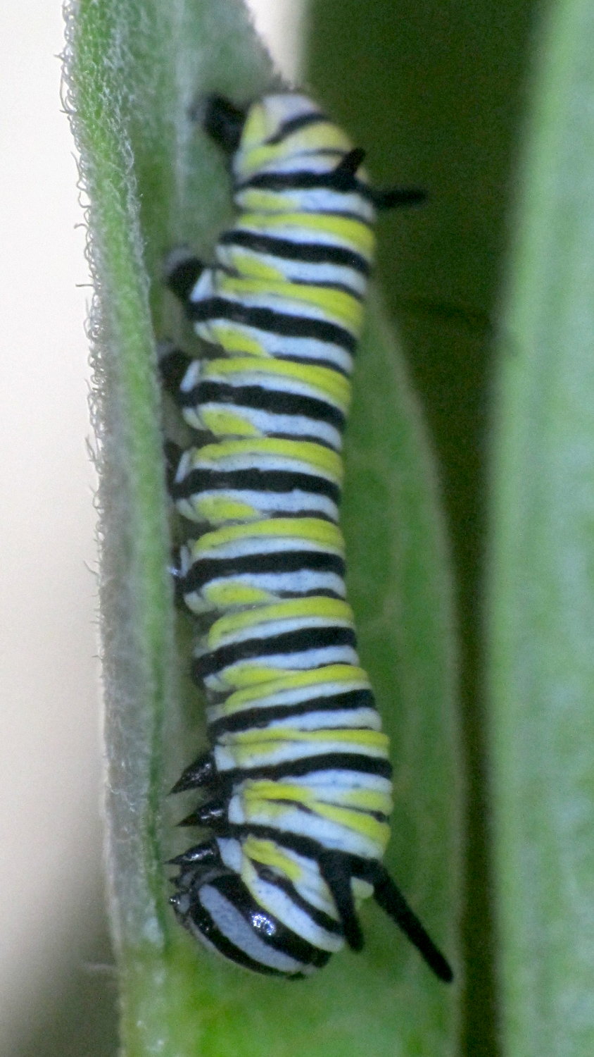
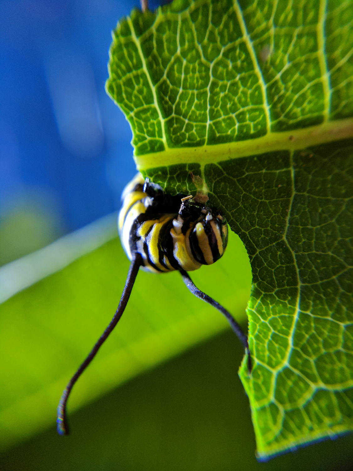
We kept fresh milkweed branches in a vase and the caterpillar ate almost continuously:
Monarch caterpillar – 2017-08-13
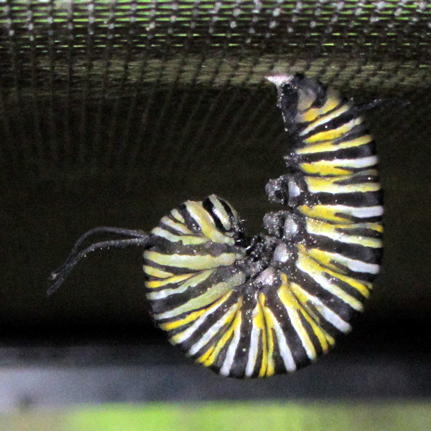
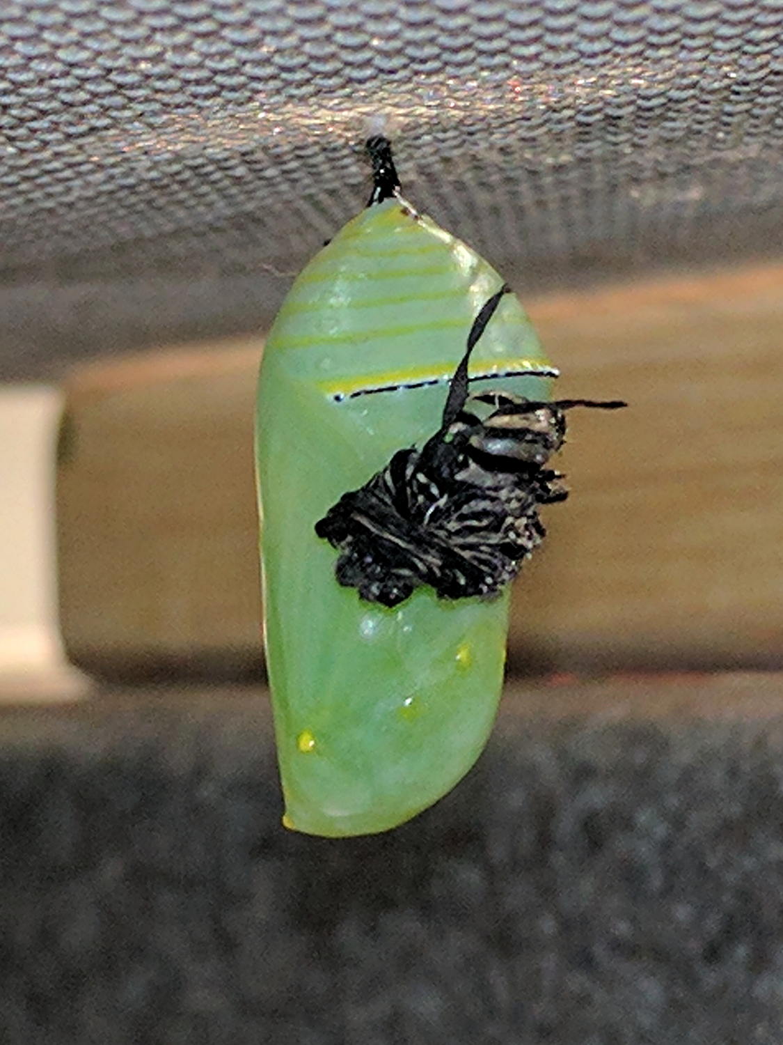
By August 15, the caterpillar was ready for the next stage in its life. At 10 in the morning it had attached itself to the screen covering the aquarium and assumed the position:
The discarded skin remained loosely attached until I carefully removed it.
What look like small yellow spots are actually a striking metallic gold color.
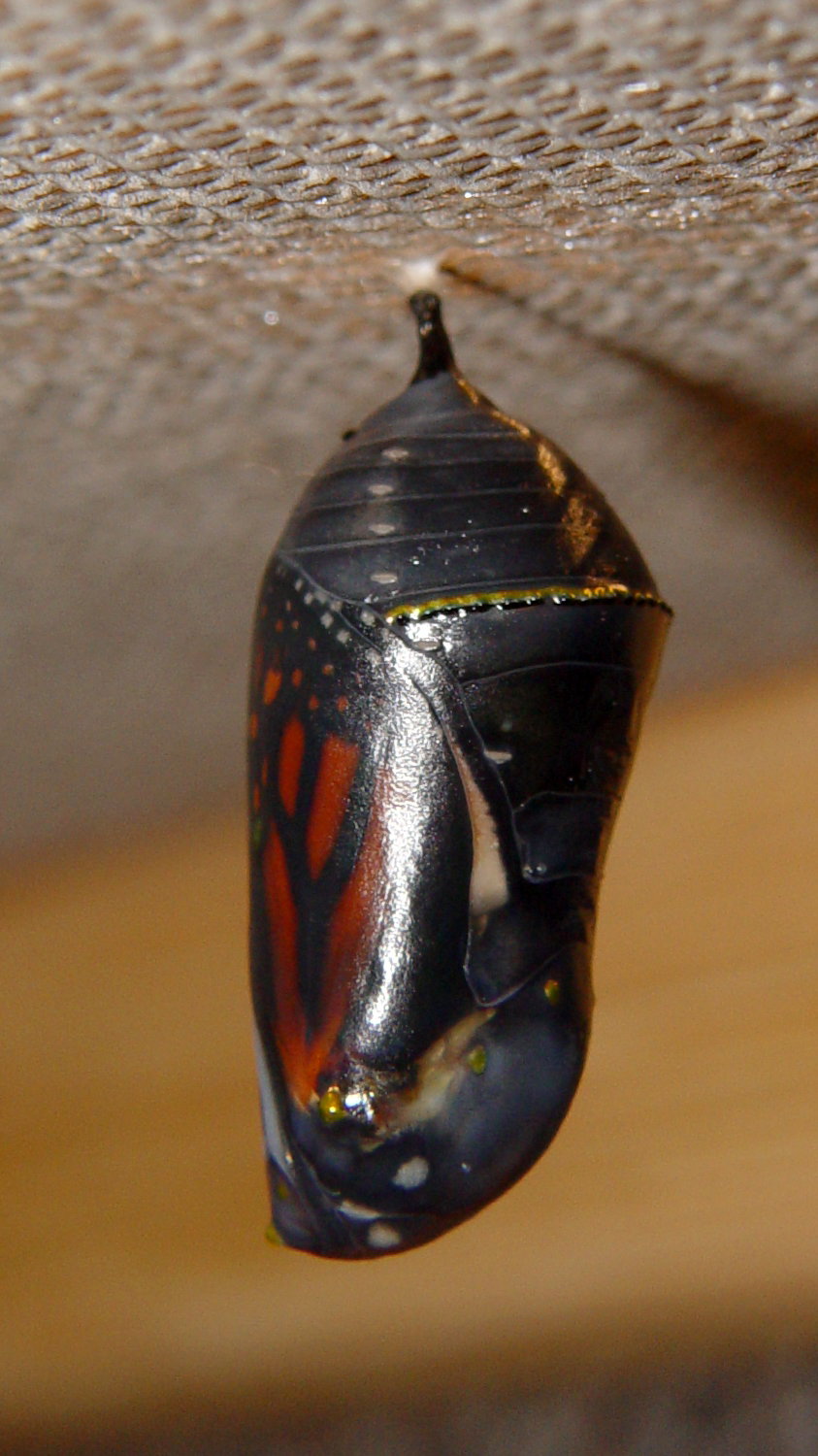
Eleven days later, on August 26 at 9 AM, the chrysalis suddenly became transparent:
Monarch chrysalis – ready – left
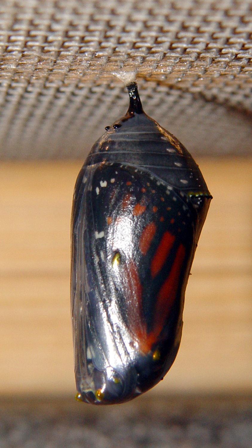
And:
Monarch chrysalis – ready – right
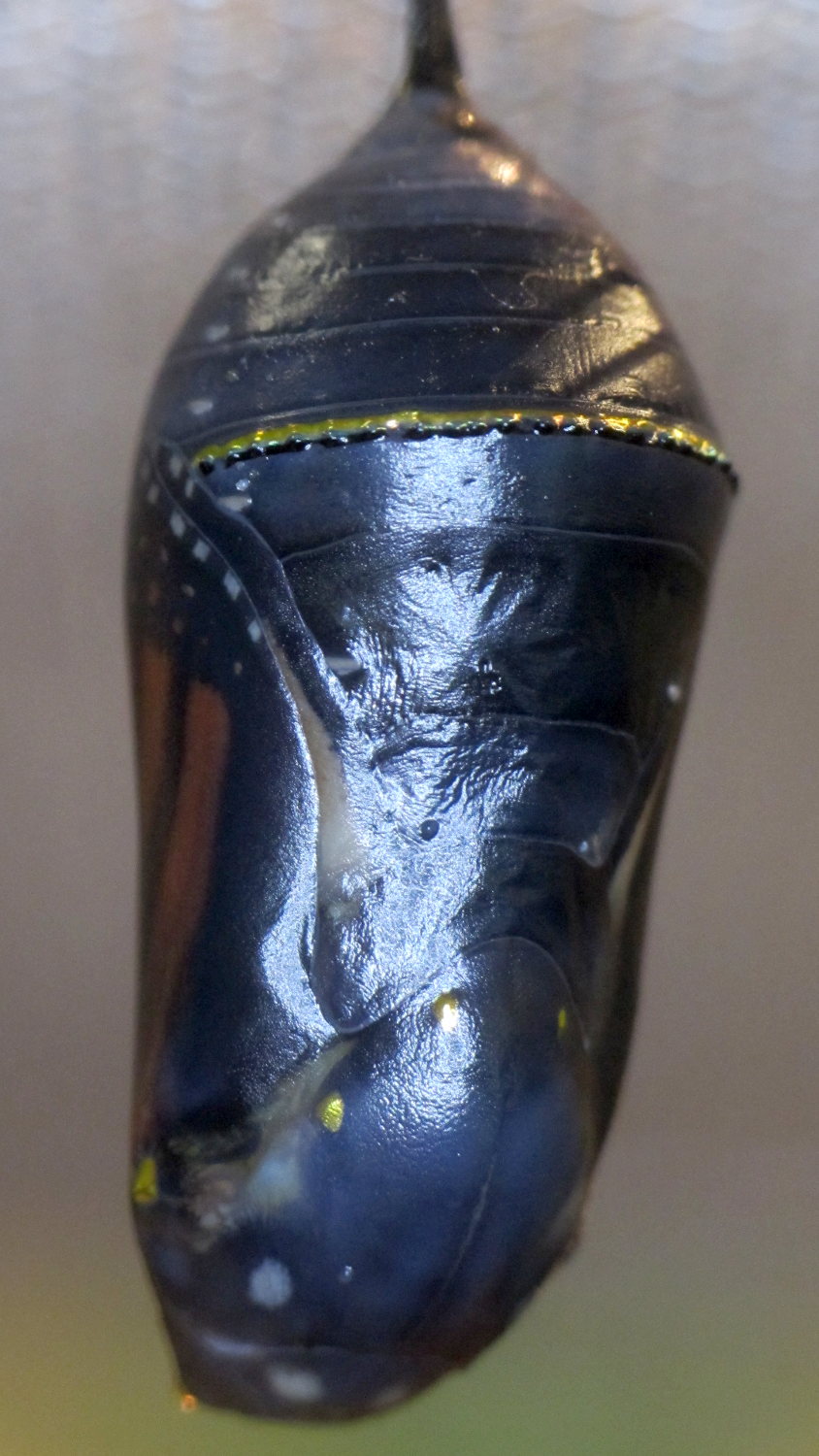
The shape of the butterfly becomes visible in reflected light:
Monarch chrysalis – ready – ventral detail
The gold dots and line remained visible.
The magic happened at 3 PM:
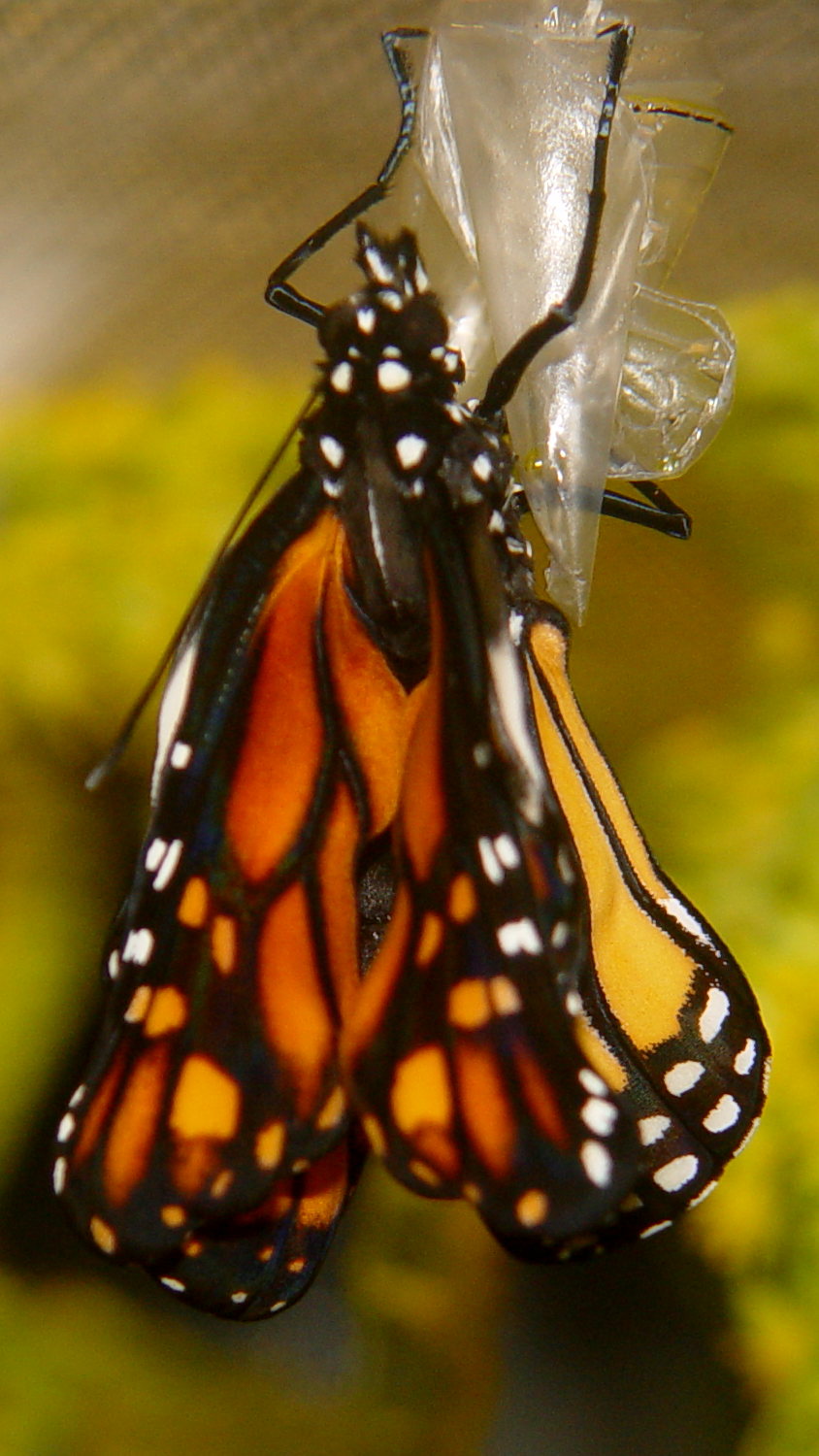
Monarch chrysalis – emerging – unfolding
The compacted wings emerge intense orange on the top and lighter orange on the bottom:
Monarch unfolding – left
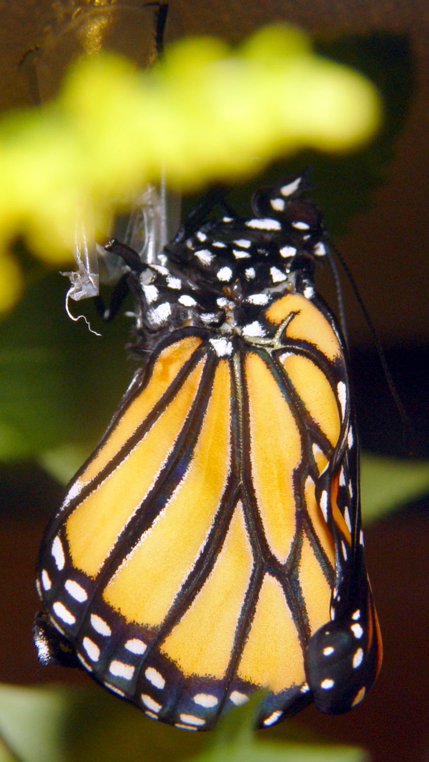
The butterfly took most of the day to unfurl and stiffen its wings into flat plates:
Monarch unfolding – dorsal
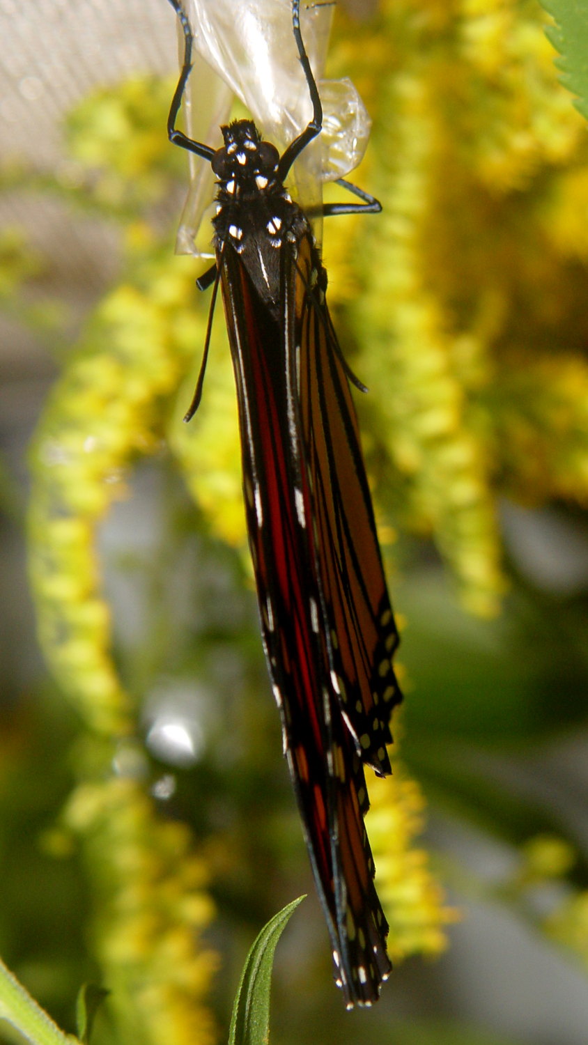
And:
Monarch unfolding – right
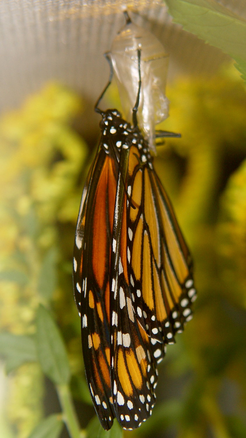
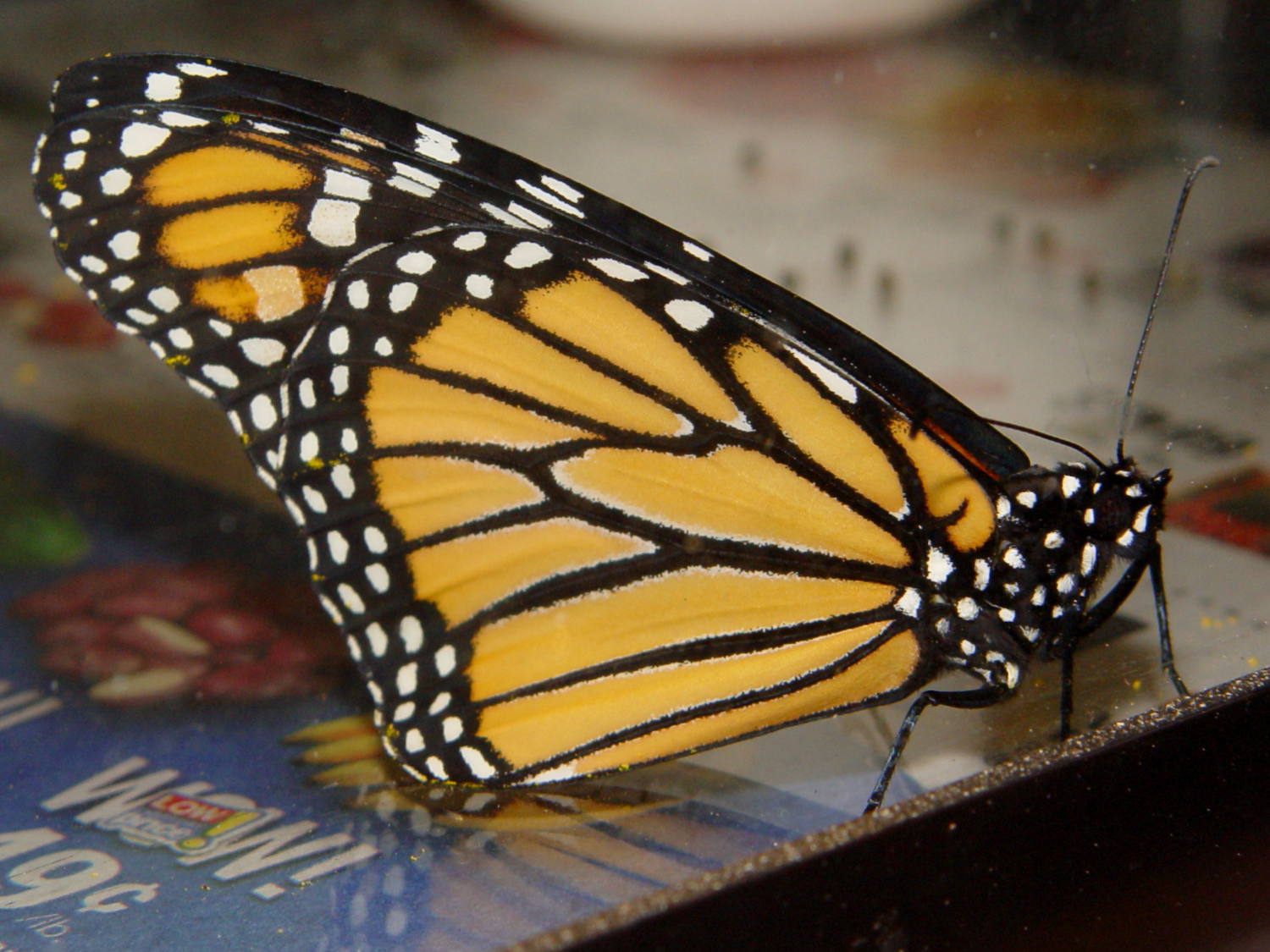
By 8 PM it began exploring the aquarium:
Monarch unfolded – right
As adults, they sip nectar from flowers, but don’t feed for the first day, so we left it in the aquarium overnight.
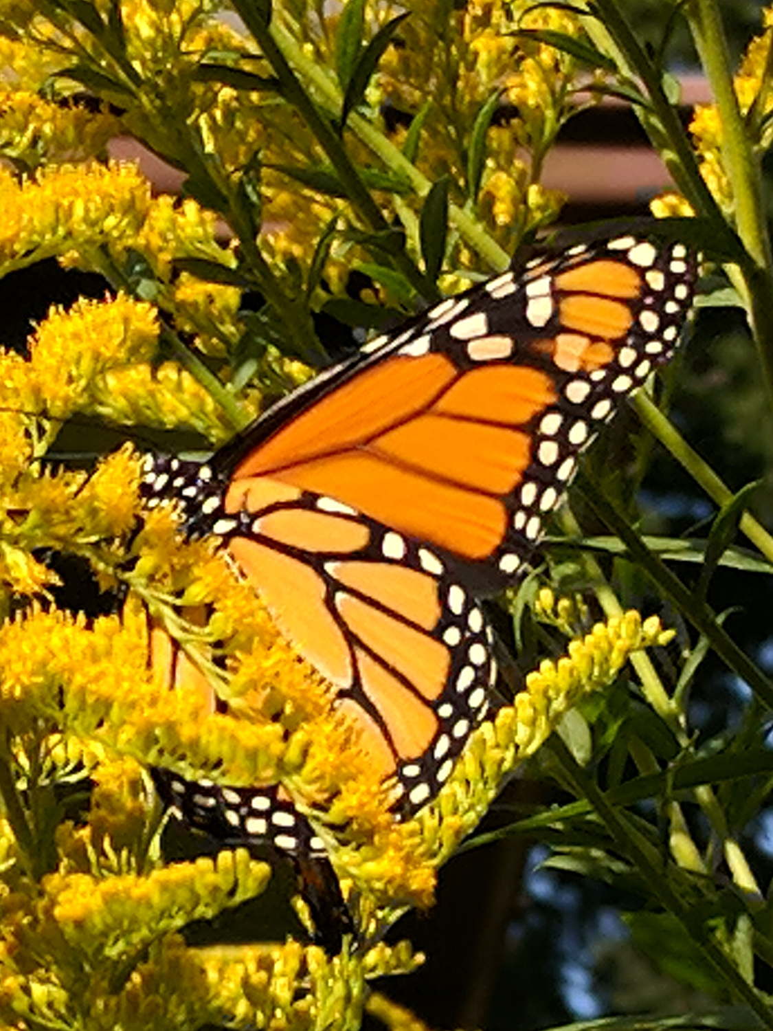
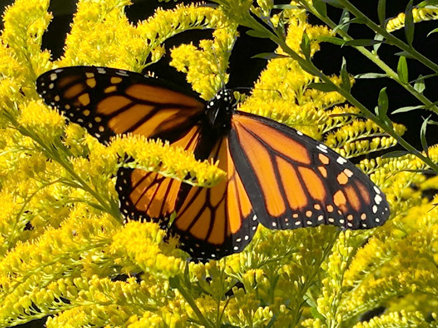
At 10 AM on August 27, we transported it to the goldenrod in the garden, where it immediately began tanking operations:
Monarch on Milkweed – left
A few minutes later, it began sun-warming operations:
Monarch on Milkweed – dorsal
Mary watched it while she was tending the garden and, an hour or so later, saw it take off and fly over the house in a generally southwest direction. It will cross half the continent under a geas prohibiting any other action, eventually overwinter in Mexico with far too few of its compadres, then die after producing the eggs for a generation beginning the northward journey next year.
Godspeed, little butterfly, godspeed …
In the spirit of “video or it didn’t happen”, there’s a 15 fps movie of the emergence taken at 5 s/image.
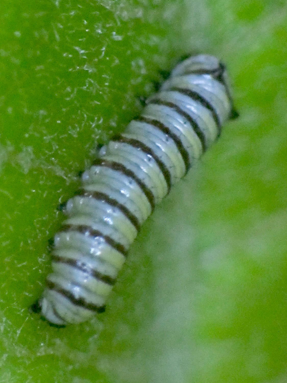
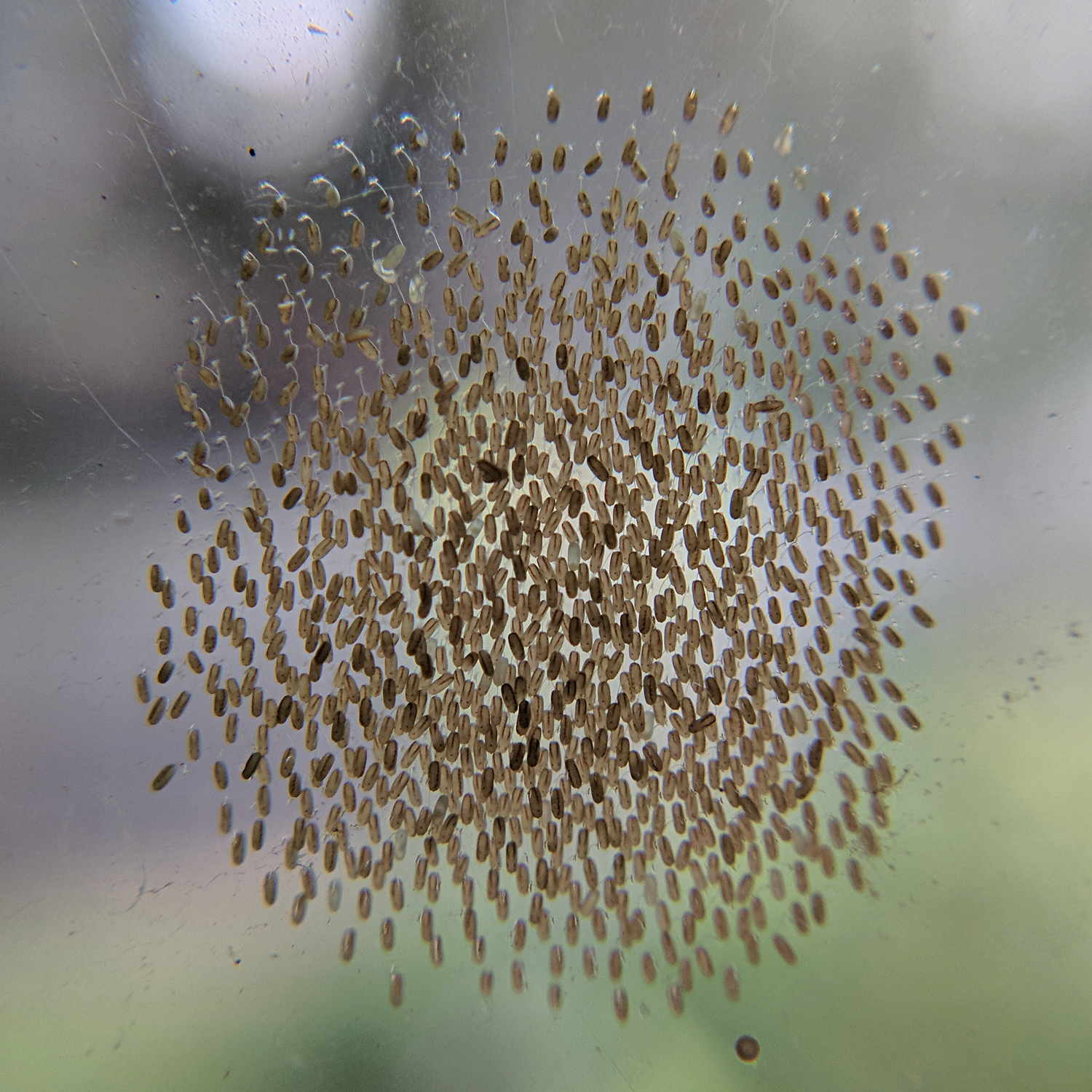
An array of tiny eggs appeared on the outside of our bedroom window:
Insect eggs on glass – 2017-09-17
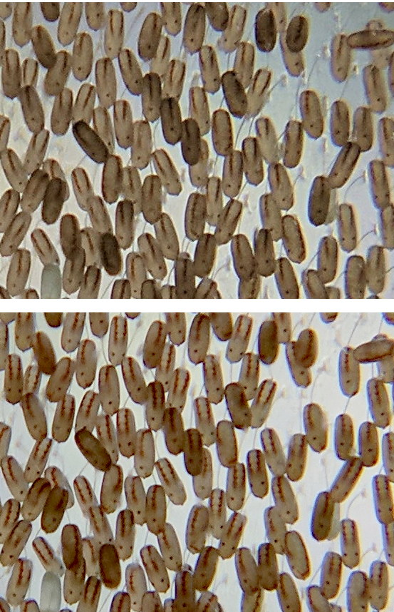
The patch measures 12 mm across and 14 mm tall. From across the room, it looks like a smudge, but it consists of hundreds of eggs, each on a tiny stalk glued to the glass:
IMG_20170919 vs 0917- Insect eggs on glass
The bottom image is two days later than the top one, both are scaled to about the same size and contrast. The critters look about the same, although I think the lines have more prominent ripples or bumps.
We have no idea what they’ll turn into, but they certainly look like they have two eyes and wings …
Datasheets loosely associated with the tuning fork resonators in hand suggest 1 μW maximum drive power, which works out to maybe 100 mVrms = 150 mVpk at about 10 kΩ ESR. If you inadvertently apply 500 mVpk = 375 mVrms, the resulting 14 μW does this:
Broken 60 kHz Tuning Fork Resonator – overview
I was applying a precisely tuned 60 kHz sine wave to the first pass at a crystal filter grafted onto the loop antenna preamp and wasn’t paying attention to the amplitude. For all I know, though, the poor thing died from a power-on transient. I’m pretty sure I didn’t break it during extraction, because it stopped being a resonator while in the circuit.
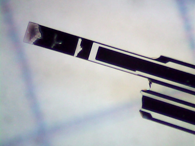
The missing tine fell out of the can:
Broken 60 kHz Tuning Fork Resonator – tine detail
Laser trim scars form a triangle near the tip, a T a bit further down, a slot just above the nicely etched gap.
A closer look at the fractured base:
Broken 60 kHz Tuning Fork Resonator – detail
The metalization appears black here and gold in person.
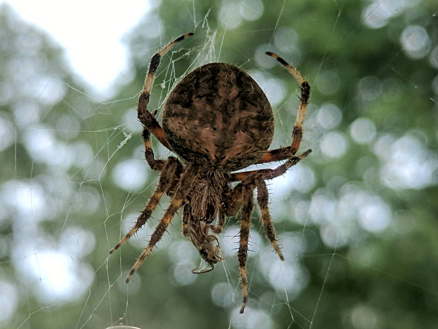
Once again, the season of orb-weavingspiders has arrived, with this one building her web across a living room window:
Orb Weaving Spider – with insect
I set the Sony HDR-AS30V atop a tripod, told it to take photos at 5 second intervals, then stitched the images into a Youtube video. It won’t go viral, but watching the spider construct her web over the course of two hours was fascinating.
She finishes the spiral at about 1 m video = 1.25 h real time, settles down for what might be a nap (it’s hard to tell with spiders), and has an insect join her for supper at 1:28, half an hour later. Spiders go from “inert” to “death incoming” almost instantly, even in real time running.
Another orb weaver set up shop in the adjacent window, but moved out the next day. Perhaps there’s a minimum spacing requirement?
Two more orb weavers guard windows in the kitchen and laundry room. We sometimes leave the lights on for them.
YouTube has other web-building videos with far more detail, of course.
The magic incantation to create the video from a directory of images in the form DSC01234.JPG:
sn=1 ; for f in *JPG ; do printf -v dn 'dsc%04d.jpg' "$(( sn++ ))" ; mv $f $dn ; done
ffmpeg -r 15 -i /mnt/video/2017-09-03/100MSDCF/dsc%04d.jpg -q 1 Orb-Weaving-2017-09-03.mp4
Perhaps each resonator’s frequency depends on its (laser-trimmed) tine mass and follows a more-or-less normal distribution, but the parallel-serial difference series capacitor changes the frequency based on (well-controlled) etched dimensions producing quantized results from three different masks / wafers / lots, with the motional inductance and capacitance incompletely modeling the physics?
Producing the histograms uses the LibreOffice frequency() array function, which requires remembering to whack Ctrl-Shift Enter to activate the function’s array-ness.
[Update: Faceplant about “parallel” resonance, which is actually the shifted resonant peak due to the 24 pF series cap. Apparently I typo-ed the second histogram subheading and ran with the error; the figures are now correct.]
The usual model for a quartz resonator apportions half the measured both-leads-to-case capacitance to each lead:
AT26 crystal capacitance fixture – Cpar detail
These AT26 / TF26 cases run around 0.6 pF, so each parasitic capacitor is 300 fF:
60 kHz Quartz Resonator – model
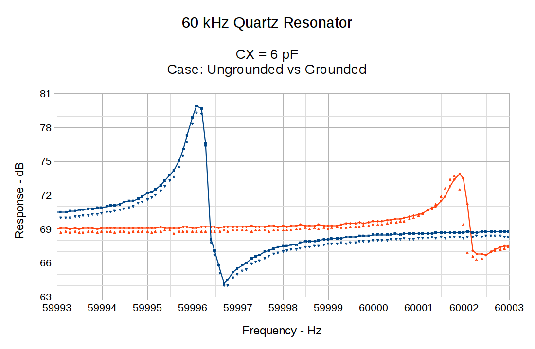
For ordinary quartz crystals, you solder the case to the ground plane to get rid of the sneak path around the central capacitor (normally C0, but labeling it properly in LTSpice just isn’t happening), but those little aluminum cans aren’t solderable. One could blob some Wire Glue over them, but …
So I just wrapped a wire around the case and soldered it to a convenient ground point under the board:
Solid lines = case ungrounded. Dotties = case grounded.
Grounding the case knocks the off-peak response down by less than 1 dB. The on-peak response remains about the same, so eliminating the series capacitance does reduce the blowthrough.
With the case grounded and CX = 6 pF in the circuit, the peaks over on the right seem ever so slightly lower in frequency, which suggests a slightly higher motional capacitance. There’s not much to write home about, though, so I’d say there’s very little effect, even on this scale.