Ed Nisley's Blog: Shop notes, electronics, firmware, machinery, 3D printing, laser cuttery, and curiosities. Contents: 100% human thinking, 0% AI slop.
Category: Science
If you measure something often enough, it becomes science
Riding south on Rt 376 takes us across the Mighty Wappinger Creek on a four-lane concrete bridge built about 1995. This Dutchess County Aerial Access photo shows it in 2016:
Rt 376 – Wappinger Bridge – 2016 overhead
A pothole opened up on the south end of the span last year:
This year, we’ve been avoiding a new pothole opening on the north end:
Rt 376 – Wapp Bridge – 2019-09-11 – 0295
It’s difficult to ride between the right side of the hole and the weeds growing from the curb joint under the guide rail, so we take the lane whenever we can. The extensive vegetation growing in the bridge structure can’t possibly be a good thing.
The concrete seems to be failing by tension overload as the beams flex downward under traffic loading and pull the top surface apart. The surface has irregular transverse cracks across the deck width, not all of which look like control joints.
With potholes and surrounding cracks allowing brine into the deck, we expect much worse deterioration during the next few years.
My Professional Engineer license has long lapsed, not that I ever knew anything about bridge design, so this is mostly observational.
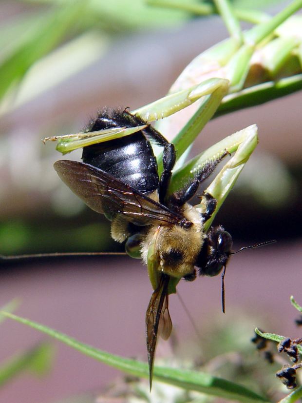
The Butterfly Bush outside the living room continues to attract flying insects, but, with the arrival of this year’s bumper crop of Praying Mantises, it has become something of a killing field.
If I hadn’t seen this, I wouldn’t have believed it:
Mantis vs Bumblebee – grapple
Perhaps grabbing the bumblebee at the tip of the abdomen neutralizes the sting, but I only saw the flash of motion, not the actual capture.
The mantis changed her (?) grip several times while removing various accessories:
Mantis vs Bumblebee – disassembly
Although a bee’s leg may not seem edible, she chewed through them like Pocky.
Minus most of the bits and pieces, serious eating commenced:
Mantis vs Bumblebee – lunch
Having watched several insects go through this process, the mantis proceeds from the head downward, eventually squeezing the abdomen like a tube of toothpaste.
A mantis can eat a bumblebee in about twenty minutes, from capture to discarding the empty husk. After a few minutes of body maintenance, ranging from leg cleaning to eye scraping, she begins waiting for the next meal to arrive …
The display on Mary’s Cateye Astrale “Cyclocomputer” had once again faded to gray, so it’s time for a new CR2032 lithium cell:
Cateye Astrale – battery change 2019-09-22
The old cell read 2.5 V, well below what it should be.
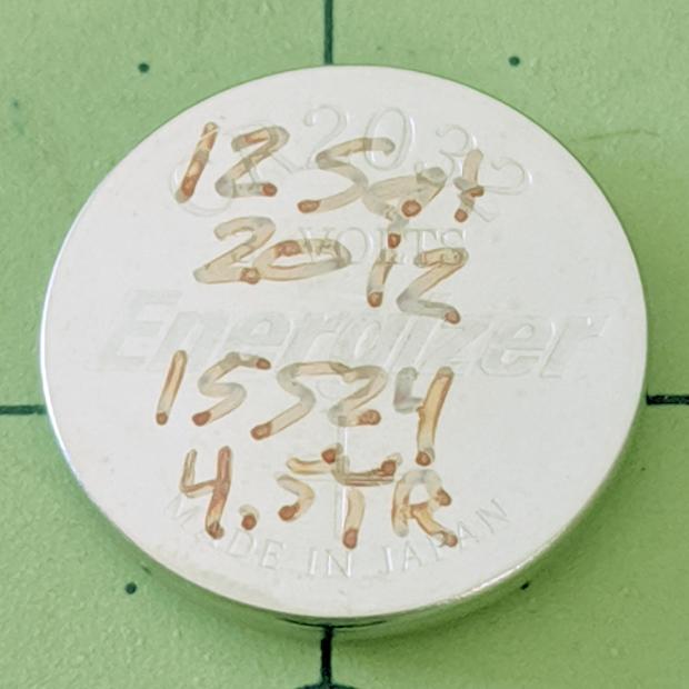
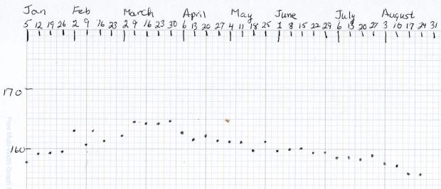
The notes scrawled on the cell become readable under better light:
Cateye Astrale – CR2032 life
Seven years (at 1942 mile/yr) ain’t bad at all!
To replace the cell fast enough to maintain the odometer reading, just unscrew & remove the battery cover, slam the back of the Astrale on the bench, and pop in the new cell.
Maybe I should replace the cell twice a decade, regardless of how feeble it might be?
Two Funnel Weaver spiders spun their webs across diagonal corners of the garden tool rack and appear to be peacefully sharing the bounty attracted by nearby lights.
The one on the left vanishes instantly into its funnel, deep inside the corner post, nearly every time we step onto the patio:
Funnel Weaver spider – tool rack left
The other spider worked around a stick emerging from its refuge:
Funnel Weaver spider – tool rack right
But it’s doing all right:
Funnel Weaver spider – tool rack right – detail
Their less adventurous compadres build webs on the plaintains festooning what might be called our lawn, making me feel awful while mowing in these months. I hope the mower’s vibrations drive them deep into the grass before it roars overhead, but I’ll never know.
Having previously concluded running the CNC 3018-Pro steppers from 12 V would let the DRV8825 chips provide better current control in Fast Decay mode at reasonable speeds, I wondered what effect a 24 V supply would have at absurdly high speeds with the driver in 1:8 microstep mode to reduce the IRQ rate.
So, in what follows, the DRV8825 chip runs in 1:8 microstep mode with Fast Decay current control. You must apply some hardware hackage to the CAMTool V 3.3 board on the CNC 3018-Pro to use those modes.
In all the scope pix, horizontal sync comes from the DRV8825 Home pulse in the top trace, with the current in the two windings of the X axis motor in the lower traces at 1 A/div. Because only the X axis is moving, the actual axis speed matches the programmed feed rate.
Homework: figure out the equivalent two-axis-moving speed.
The 12 V motor supply works well at 140 mm/min, with Fast Decay mode producing clean microstep current levels and transitions:
3018 X – Fast – 12V – 140mm-min 1A-div
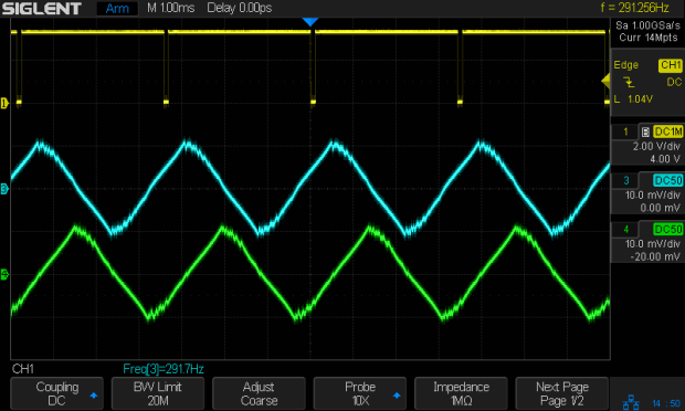
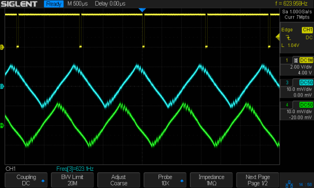
The sine waves deteriorate into triangles around 1400 mm/min, suggesting this is about as fast as you’d want to go with a 12 V supply:
3018 X – Fast – 12V – 1400mm-min 1A-div
Although the axis can reach 3000 mm/min, it’s obviously running well beyond its limits:
3018 X – Fast – 12V – 3000mm-min 1A-div
The back EMF fights the 12 V supply to a standstill during most of the waveform, leaving only brief 500 mA peaks, so there’s no torque worth mentioning and terrible position control.
Increasing the supply to 24 V, still with 1:8 microstepping and Fast Decay …
At a nose-pickin’ slow 14 mm/min, Fast Decay mode looks rough, albeit with no missteps:
3018 X – Fast – 24V – 14mm-min 1A-div
At 140 mm/min, things look about the same:
3018 X – Fast – 24V – 140mm-min 1A-div
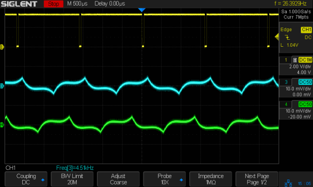
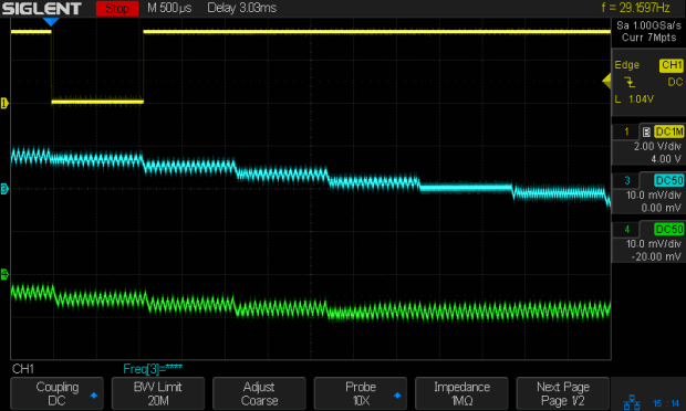
For completeness, a detailed look at the PWM current control waveforms at 140 mm/min:
3018 X – Fast detail – 24V – 140mm-min 1A-div
The dead-flat microstep in the middle trace happens when the current should be zero, which is comforting.
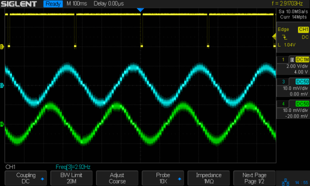
At 1400 mm/min, where the 12 V waveforms look triangular, the 24 V supply has enough mojo to control the current, with increasing roughness and slight undershoots after the zero crossings:
3018 X – Fast – 24V – 1400mm-min 1A-div
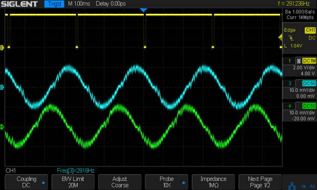
At 2000 mm/min, the DRV8825 is obviously starting to have trouble regulating the current against the increasing back EMF:
3018 X – Fast – 24V – 2000mm-min 1A-div
At 2500 mm/min, the back EMF is taking control away from the DRV8825:
3018 X – Fast – 24V – 2500mm-min 1A-div
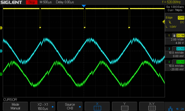
The waveforms take on a distinct triangularity at 2700 mm/min:
3018 X – Fast – 24V – 2700mm-min 1A-div
They’re fully triangular at 3000 mm/min:
3018 X – Fast – 24V – 3000mm-min 1A-div
In round numbers, you’d expect twice the voltage to give you twice the speed for a given amount of triangularity, because the current rate-of-change varies directly with the net voltage. I love it when stuff works out!
At that pace, the X axis carrier traverses the 300 mm gantry in 6 s, which is downright peppy compared to the default settings.
Bottom lines: the CNC 3018-Pro arrives with a 24 V supply that’s too high for the DRV8825 drivers in Mixed Decay mode and the CAMTool V3.3 board’s hardwired 1:32 microstep mode limits the maximum axis speed. Correcting those gives you 3000 mm/min rapids with good-looking current waveforms.
I’m reasonably sure engraving plastic and metal disks at 3000 mm/min is a Bad Idea™, but having some headroom seems desirable.
The Butterfly Bush in front of the house attracts all kinds of insects, including Monarch Butterflies (shown here on the Goldenrod planted in the garden):
Monarch on Goldenrod – left
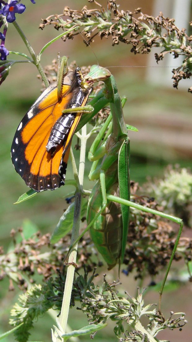
This year, the bush also attracted a Praying Mantis:
I started low-key upper-body strength training in June with encouraging results: my biceps no longer require exotic instrumentation for detection and my abs may soon transition from “throw pillow” to “two-pack”.
This is, however, the season of bounteous garden harvests, including delicious corn-on-the-cob and summer squash …