Ed Nisley's Blog: Shop notes, electronics, firmware, machinery, 3D printing, laser cuttery, and curiosities. Contents: 100% human thinking, 0% AI slop.
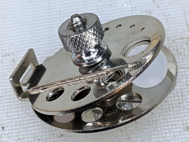
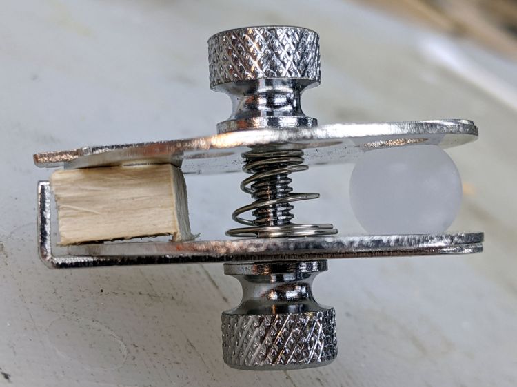
Given the angle between the two plates, I didn’t see any way to put a large hole though the center of the ball:
Micromark Ball Vise – 10 mm ball
A scrap of wood aligned the two plates somewhat better:
Micromark Ball Vise – wood block
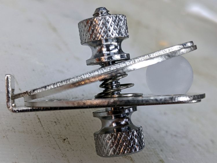
With that as a hint, the Box o’ Brass Cutoffs disgorged a better spacer, although the original screw was just an itsy too short:
Micromark Ball Vise – brass tube
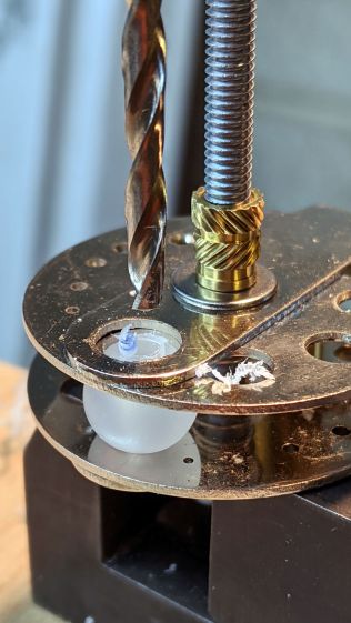
Grabbing the modified vise in a machinist’s vise got me most of the way toward the goal:
Micromark Ball Vise – drill press
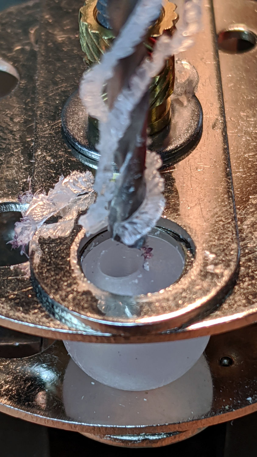
Polypropylene is grabby, so the drill stuck / rotated the ball inside the vise / made a mess:
Micromark Ball Vise – offset hole
A close look at the top picture shows the nasty ring around the hole (on the right side). The vise grips the ball between two holes punched in the metal plates, contacting it only at the right-angle (-ish) edges forming two rings, so there’s really not enough friction against the plastic to hold the ball in position and any slippage results in a gouge. Perhaps pearls / beads / jewelry behave differently?
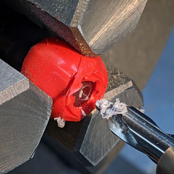
Fortunately, I had a bag of 100 balls, so a few failures gave me enough of a clue to do what I should have done from the beginning:
Micromark Ball Vise – lathe ball hack
That’s silicone tape wrapped around a ball grabbed in the lathe chuck, with a center drill in the tailstock. There’s barely enough traction between the ball and the chuck to get the job done, but it worked out well enough to build a few new mirrors:
Helmet Mirror Ball Mount – new vs old
There’s obviously a better way, although it took a few weeks to shake out the solid model …
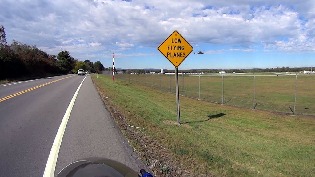
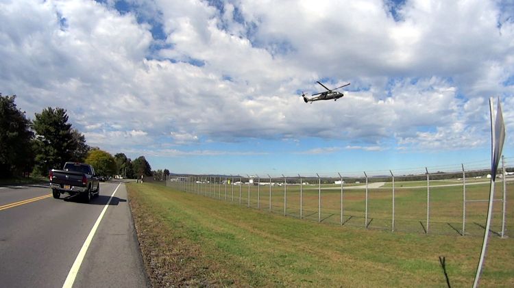
The same helicopter thumped over our house, about two miles from the runway as the chopper flies, while I was getting ready for the ride, and it was hovering as I reached the airport. I think the pilot was practicing, because the chopper made very precise movements across the airport, translated front / back / left / right, and hovered motionless for minutes at a time despite wind gusts.
The switch I installed on Mary’s bike a year ago was intended for indoor use only and, without any trace of weather sealing, recently became intermittent. No surprise, as it’s happened before, but, by regarding my vast assortment of little switches as consumables, we get a low-profile / tactile / E-Z push PTT button without forming a deep emotional attachment.
Anyhow, you can see the unsealed square perimeter of the switch actuator:
Tour Easy – PTT button
The light-gray button sits on a post molded into the actuator. Pry the actuator out and the switch dome shows crud worn off the cross-shaped plunger:
Tour Easy – PTT button – dome plate
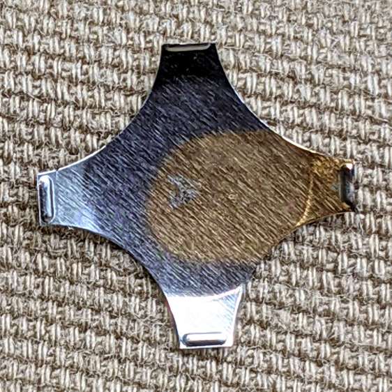
The underside of the dome has a weird golden discoloration that surely wasn’t original:
Tour Easy – PTT button – dome plate discoloration
I have no idea how a liquid (?) could have gotten in there and done that without leaving other traces along the way. The contact bump on the discolored leg had some crud built up around it which responded well to a small screwdriver.
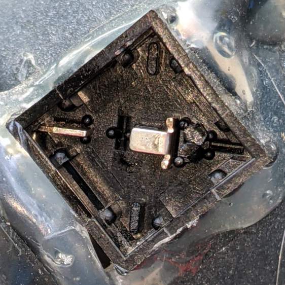
Contrary to what the symmetrical four-legged dome might suggest, only one leg rests on a contact in a corner:
Tour Easy – PTT button – contacts
So, yes, a bit of dirt / corrosion / mystery juice in a single spot could render the whole thing intermittent.
I removed the obvious crud from the obvious spots, wiped everything down with some Caig DeoxIT, reassembled in reverse order, and it seems to be all good again. Of course, these things only fail on the road, so it’ll take a few rides to verify the fix.
The NYS DOT has been improving the pedestrian crossings at the Burnett – Rt 55 intersection. I expect this will be a bullet item in their Complete Streets compliance document, with favorable job reviews for all parties. The situation for bicyclists using the intersection, which provides the only access from Poughkeepsie to the Dutchess Rail Trail, hasn’t changed in the slightest. No signal timing adjustments, no bike-capable sensor loops, no lane markings, no shoulders, no nothing.
Here’s what NYS DOT’s Complete Streets program looks like from our perspective, with the four-digit frame numbers ticking along at 60 frame/sec.
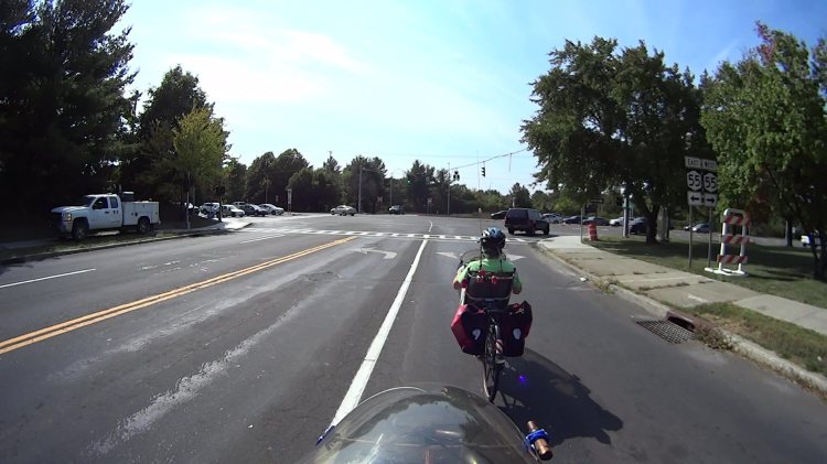
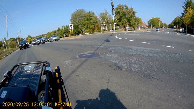
We’re waiting on Overocker Rd for Burnett traffic to clear enough to cross three lanes from a cold start:
Burnett Signal – 2020-09-25 – front 0006
That building over there across Burnett is the NYS DOT Region 8 Headquarters, so we’re not in the hinterlands where nobody ever goes.
About 1.5 seconds later, the vehicles have started moving and we’re lining up for the left side of the right-hand lane:
Burnett Signal – 2020-09-25 – front 0752
There’s no traffic behind us, so we can ride a little more to the right than we usually do, in the hopes of triggering the signal’s unmarked sensor loop:
Burnett Signal – 2020-09-25 – front 1178
We didn’t expect anything different:
Burnett Signal – 2020-09-25 – front 1333
We’re rolling at about 12 mph and it’s unreasonable to expect us to jam to a stop whenever the signal turns yellow. Oh, did you notice the truck parked in the sidewalk over on the left?
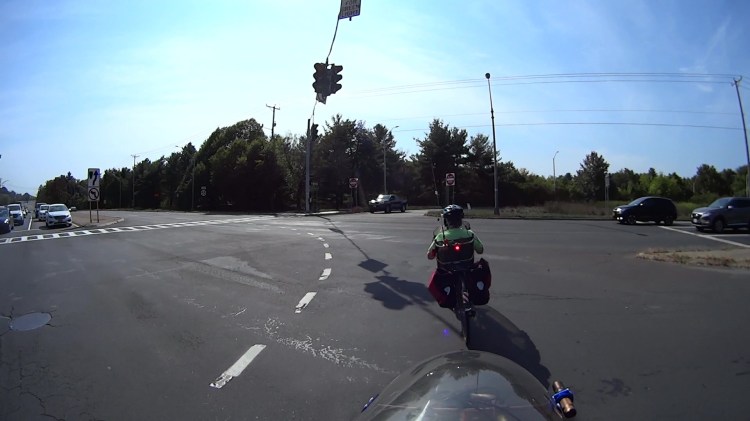
As usual, 4.3 seconds later, the Burnett signals turn red, so we’re now riding in the “intersection clearing” delay:
One second later, we’re still proceeding through the intersection, clearing the lethally smooth manhole cover by a few inches, and approaching the far side:
Burnett Signal – 2020-09-25 – front 1771
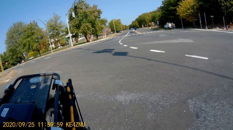
Here’s what the intersection looks like behind me:
Burnett Signal – 2020-09-25 – rear 1
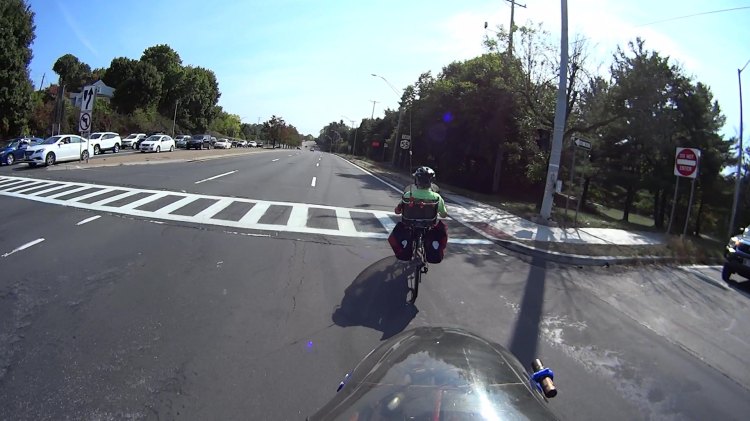
Another second goes by and we’re pretty much into the far right lane , with the westbound traffic beginning to move:
Burnett Signal – 2020-09-25 – front 1831
The pedestrian crossing ladder has fresh new paint. They milled off the old paint while reconstructing the crossing, so the scarred asphalt will deteriorate into potholes after a few freeze-thaw cycles. Not their problem, it seems.
Although it’s been three seconds since Rt 55 got a green signal, the eastbound drivers remain stunned by our presence:
Burnett Signal – 2020-09-25 – rear 2
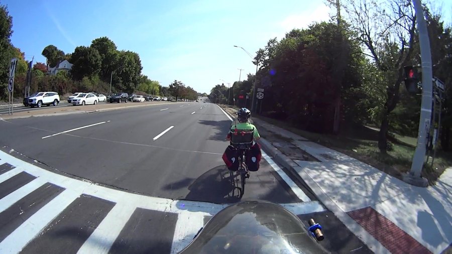
After another second, we’re almost where we need to be:
Burnett Signal – 2020-09-25 – front 1891
There’s a new concrete sidewalk on the right, with a wheelchair-accessible signal button I can now hit with my elbow when we’re headed in the other direction. It’s worth noting there is no way to reach Overocker by bicycle, other than riding the sidewalk; there’s only one “complete” direction for vehicular cyclists.
One second later puts us as far to the right as we can get, given all the gravel / debris / deteriorated asphalt along the fog line near the curb:
Burnett Signal – 2020-09-25 – front 1957
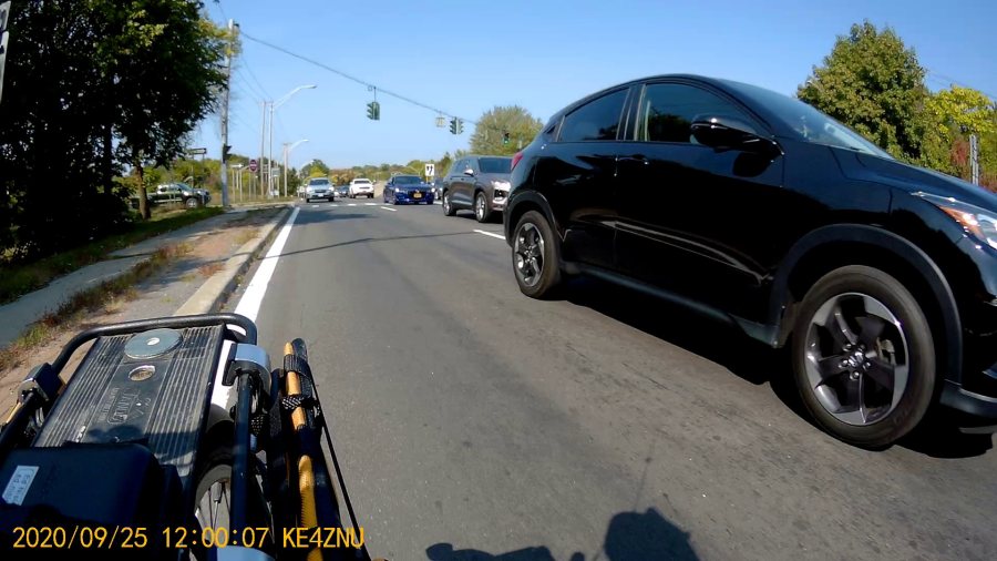
Which is good, because four seconds after the green signal for Rt 55, the pack has overtaken us:
Burnett Signal – 2020-09-25 – rear 3
If you were the driver of the grayish car in the middle lane, directly behind the black one giving us plenty of room, you might be surprised at the abrupt lane change in front of you. Maybe not, because you had a front-row seat while we went through the intersection.
Elapsed time from the green signal on Burnett: 25 seconds. My point is that another few seconds of all-red intersection clearing time wouldn’t materially affect anybody’s day and would go a long way toward improving bicycle safety.
Unlike the pedestrian crossing upgrade, NYS DOT could fix this with zero capital expenditure: one engineer with keys to the control box, a screwdriver or keyboard (depending on the age of the controls), and the ability to do the right thing could fix it before lunch tomorrow.
The general idea is to hold the wave washer (it’s mashed under the flat washer, honest) above those bumps on the plate holding the mirror and stalk balls. It’s a few millimeters from the end of a ¼ inch brass rod, drilled for the M3 screw, and reduced to 4.5 mm with a parting tool to clear the bumps.
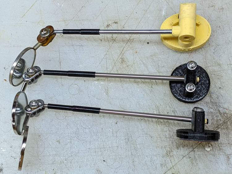
While I was at it, I made two spare mirrors, just to have ’em around:
I should replace the steel clamp plates with a stainless-steel doodad of some sort to eliminate the unsightly rust, but that’s definitely in the nature of fine tuning.
However, it’s worth noting my original, butt-ugly Az-El mounts lasted for all of those nine years, admittedly with adjustments along the way, which is far more than the commercial mountsmaking me unhappy enough to scratch my itch.
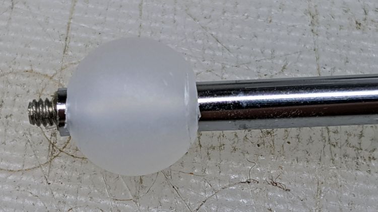
Scaling it down for a 10 mm polypropylene ball around the base of the 30 mm inspection mirror’s shaft simplified everything:
Helmet Mirror Ball Mount – drilled ball test
I’m reasonably sure I couldn’t have bought 100 polypro balls for eight bucks a decade ago, but we’ll never know. Drilling the hole was a complete botch job, about which more later. The shaft came from a spare mirror mount I made up a while ago; a new shaft appears below.
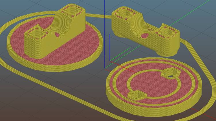
The solid model, like Gaul, is in three parts divided:
Helmet Mirror Ball Mount – Slic3r
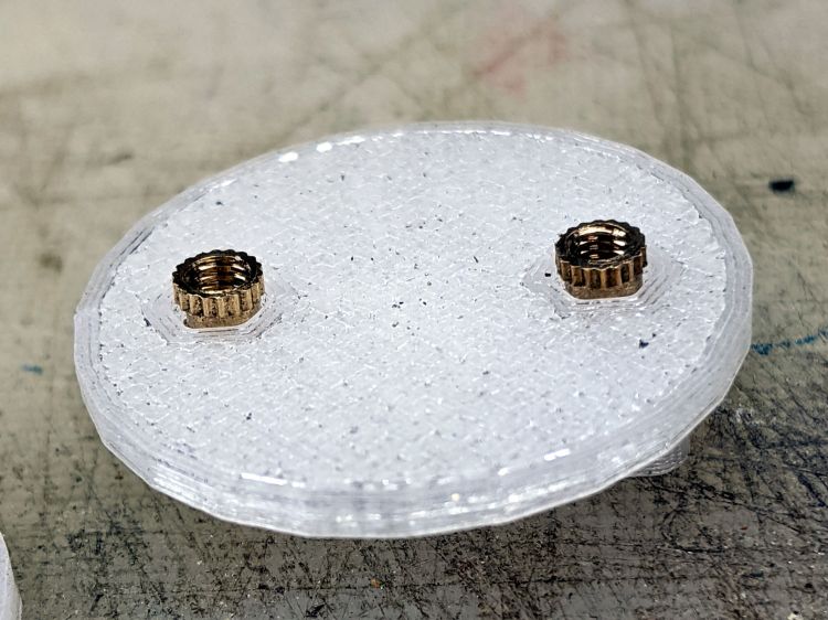
The helmet plate (on the right) has a slight indent more-or-less matching the helmet curvature and gets a layer of good double-stick foam tape. The clamp base (on the left) has a pair of brass inserts epoxied into matching recesses below the M3 clearance holes:
Helmet Mirror Ball Mount – inserts
A layer of epoxy then sticks the helmet plate in place, with the inserts providing positive alignment:
Helmet Mirror Ball Mount – plates
The clamp screws pull the inserts against the plastic in the clamp base, so they can’t pull out or through, and the plates give the epoxy enough bonding surface that (I’m pretty sure) they won’t ever come apart.
I turned down a 2 mm brass insert to fit inside the butt end of the mirror shaft and topped it off with a random screw harvested from a dead hard drive:
Helmet Mirror Ball Mount – assembled – rear view
At the start, it wasn’t obvious the shaft would stay stuck in the ball, so I figured making it impossible to pull out would eliminate the need to find it by the side of the road. As things turned out, the clamp exerts enough force to ensure the shaft ain’t goin’ nowhere, so I’ll plug future shafts with epoxy.
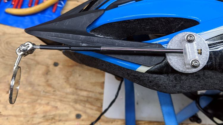
The front side of the clamp looks downright sleek:
Helmet Mirror Ball Mount – assembled – front view
Well, how about “chunky”?
The weird gray-black highlights are optical effects from clear / natural PETG, rather than embedded grunge; it looks better in person. I should have used retina-burn orange or stylin’ black.
This mount is much smaller than the old one and should, in the event of a crash, not cause much injury. Based on how the running light clamp fractures, I expect the clamp will simply tear out of the base on impact. In the last decade, neither of us has crashed, so I don’t know what the old mount would do.
The clamp is 7 mm thick (front-to-back), set by the M3 washer diameter, with 1.5 mm of ball sticking out on each side. The model has a kerf one thread high (0.25 mm) between the pieces to add clamping force and, with the screws tightened down, moving the ball requires a disturbingly large effort. I added a touch of rosin and that ball straight-up won’t move, which probably means the shaft will bend upon droppage; I have several spare mirrors in stock.
On the other paw, the ball turns smoothly in the clamp and it’s easy to position the shaft as needed: much better than the old Az-El mount!
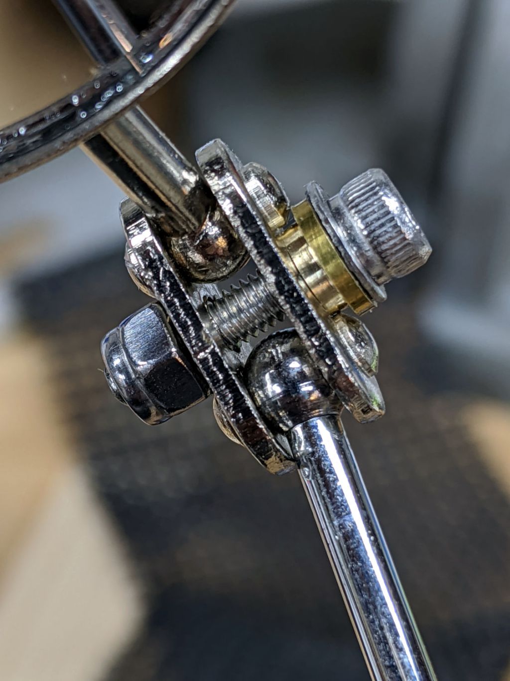
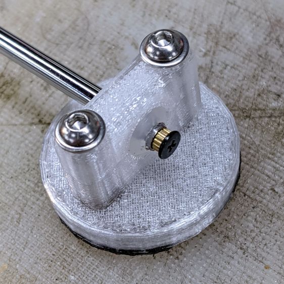
The inspection mirror hangs from a double ball joint which arrives with a crappy screw + nut. I epoxied the old mirror mount nut in place, but this time around I drilled the plates for a 3 mm stainless SHCS, used a wave washer for a bit of flexible force, and topped it off with a nyloc nut:
Helmet Mirror Ball Mount – mirror joint
I’m unhappy with how it looks and don’t like how the washer hangs in free space between those bumps, so I may eventually turn little brass fittings to even things out. It’s either that or more epoxy.
So far, though, it’s working pretty well and both units meet customer requirements.
This file contains hidden or bidirectional Unicode text that may be interpreted or compiled differently than what appears below. To review, open the file in an editor that reveals hidden Unicode characters.
Learn more about bidirectional Unicode characters
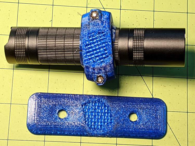
While clearing some overhanging brush along the rail trail, I probably wedged a branch between the LC40 flashlight and the fairing:
Fairing Flashlight Mount – brush clearing
Aaaand twisted it enough to fracture the mount:
Fairing Flashlight Mount – another fracture
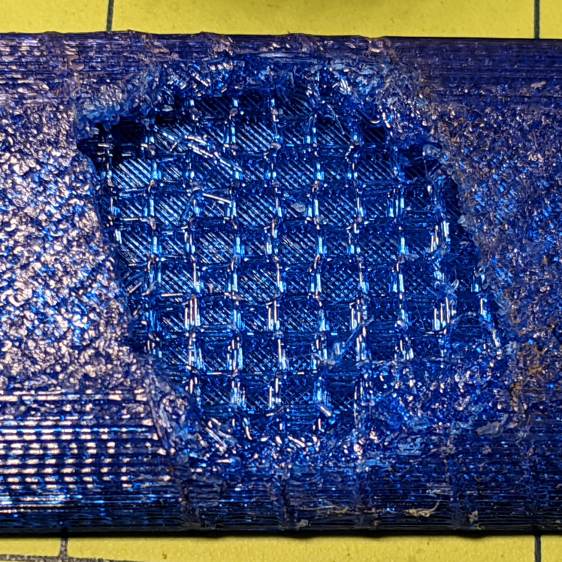
A closer look shows the infill just ripped apart:
Fairing Flashlight Mount – another failure – detail
I can’t be sure that’s what happened, because the mount actually failed several miles later, after I hit one of the potholes along Raymond Avenue. Fortunately, I saw it swinging away from the fairing, hanging by its last few threads, and managed to grab it before it vanished.
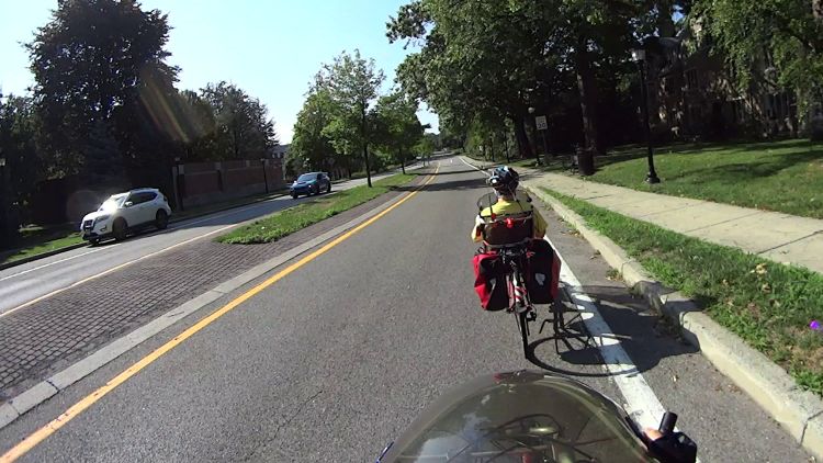
Fairing Flashlight Mount – Catch a Falling Mount
I set Slic3r for 30% infill on the replacement, but the running light been riding my fairing for three years and seems strong enough under normal use.