The Smell of Molten Projects in the Morning

Ed Nisley's Blog: Shop notes, electronics, firmware, machinery, 3D printing, laser cuttery, and curiosities. Contents: 100% human thinking, 0% AI slop.

Category: Recumbent Bicycling

Cruisin’ the streets

  • Amber Side Marker Light Hackery

    Amber Side Marker Light Hackery

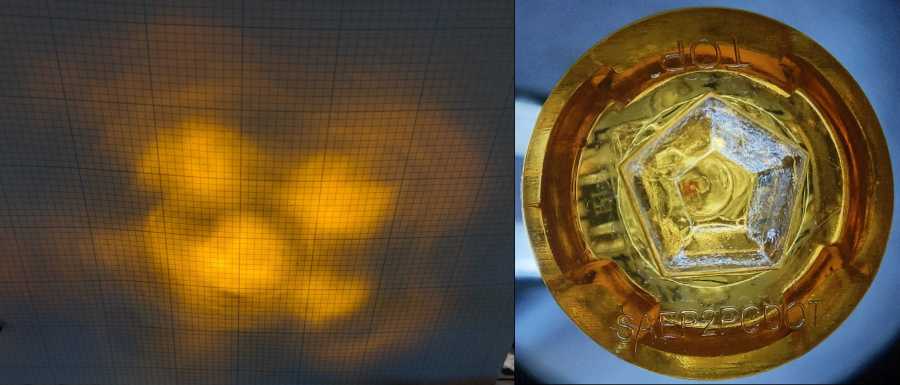
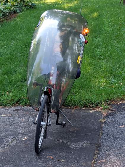
    Start with the amber side marker light sporting a cataract and distorted beam:
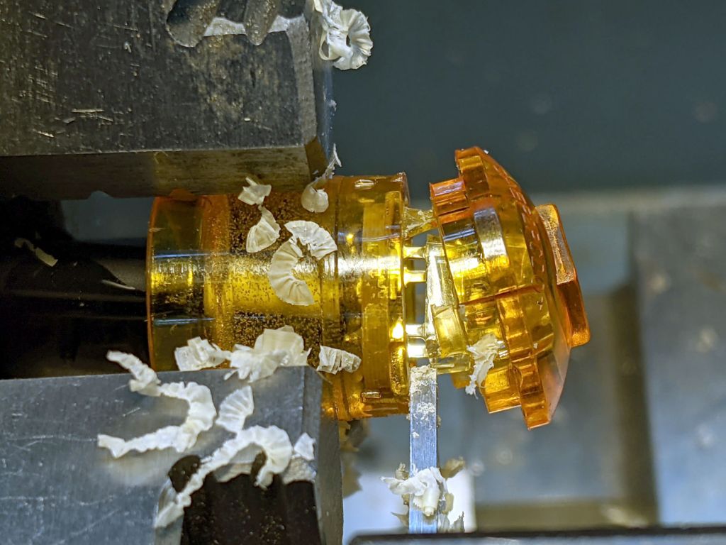
    Side Marker - beam test - E
    Side Marker – beam test – E

    Part off the lens:

    Side Marker E - cutting case
    Side Marker E – cutting case

    The cut is just in front of the PCB and went slowly to avoid clobbering the SMD resistors very near the edge.

    The cataract turned out to be crud adhered to the LED lens:

    Side Marker E - LED cataract
    Side Marker E – LED cataract

    Brutal surgery removed the LED and installed a replacement:

    Side Marker E - replacement LED
    Side Marker E – replacement LED

    The PCB had two 150 Ω SMD resistors for use with 12-ish V automotive batteries. While I had the hood up, I removed one and shorted across its pads to make the LED work with the 6 V switched headlight supply from the Bafang motor.

    In round numbers, 6 V minus 2.2 V forward drop divided by 150 Ω is about 25 mA. The original LED ran at 35-ish mA, but it’s close enough.

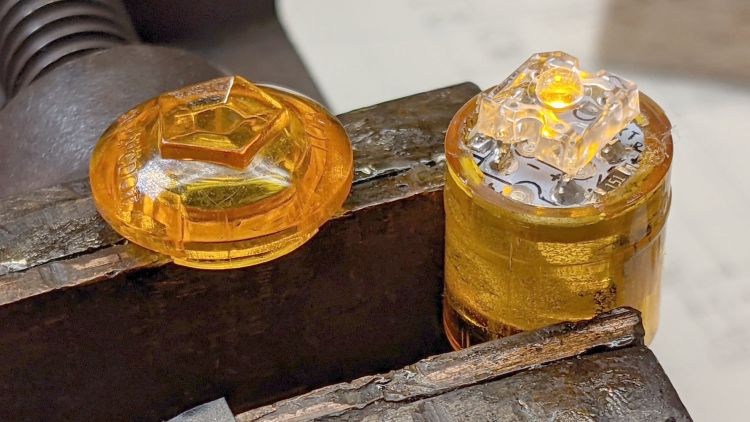
    Glue the lens back in place:

    Side Marker E - clamping case
    Side Marker E – clamping case

    The bubbly stuff is solid epoxy from the original assembly, which is why removing the PCB is not an option.

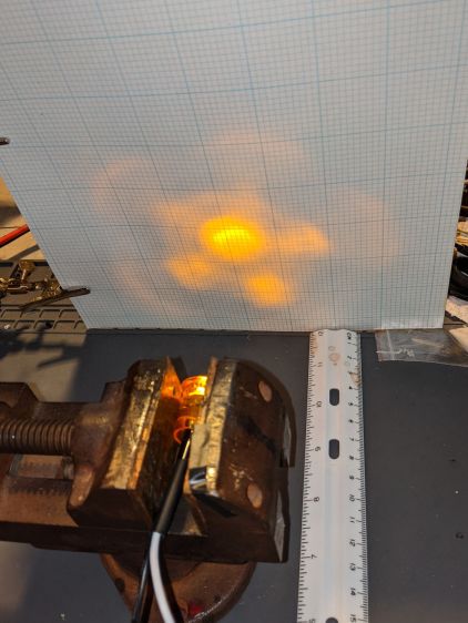
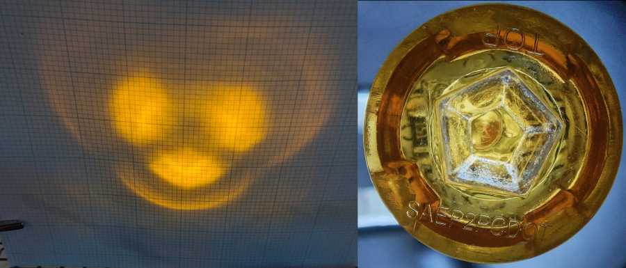
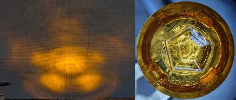
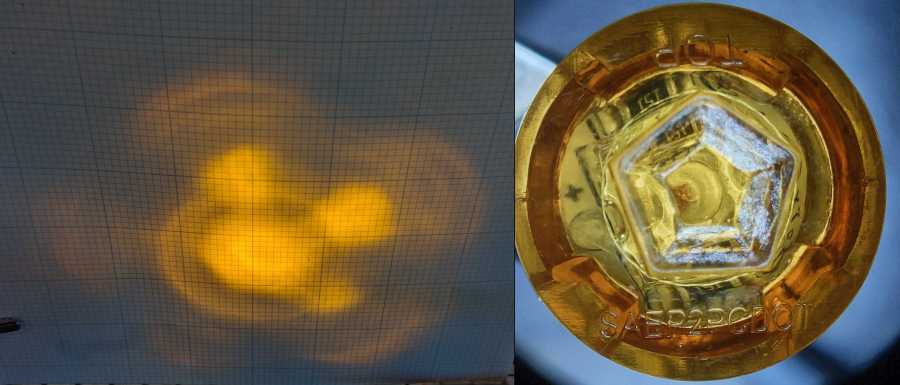
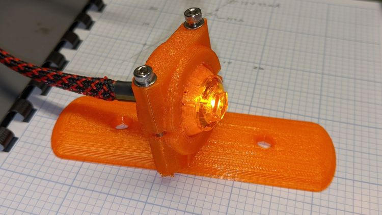
    The new LED is no more off-center than any of the others:

    Side Marker E - new LED - front
    Side Marker E – new LED – front

    It does, however, sit much closer to the lens, due to the ring of plastic I cut away to get inside. As a result, the beam is mostly a single centered lobe with only hints of the five side lobes; there isn’t much waste light from the side of the LED into those facets.

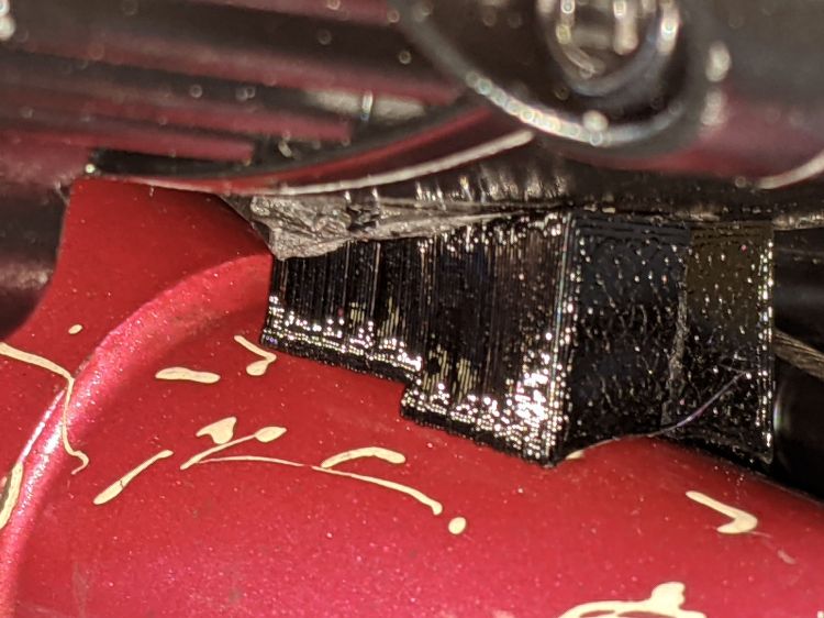
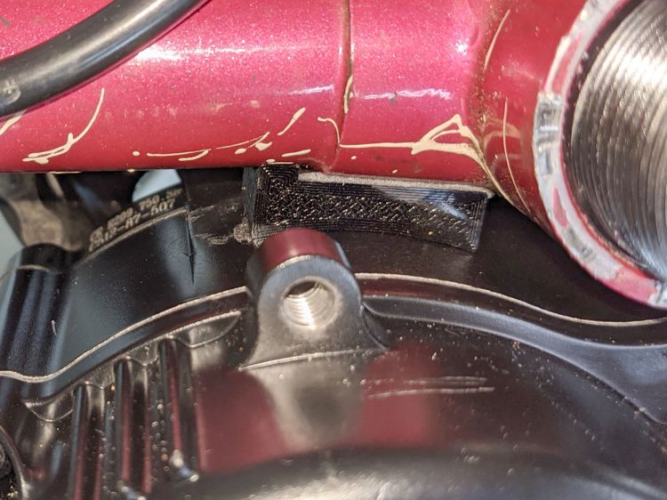
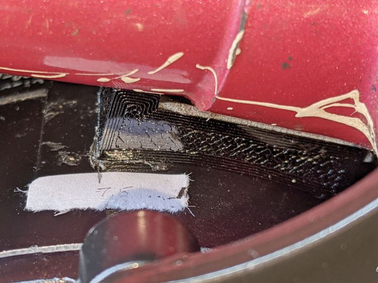
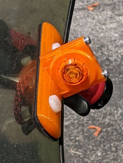
    Replace the one I originally put in the new fairing mount:

    Side Marker E rebuilt - installed
    Side Marker E rebuilt – installed

    However, it’s still not much more than a glowworm in the daytime, so we need more firepower …

  • Another Power Outage

    Another Power Outage

    We woke just after midnight to a completely dark and silent house, I padded around shutting of half a dozen UPS units under various desks and benches, and we eventually got back to sleep:

    Rt 376 midnight crash - 2021-07-20 - status
    Rt 376 midnight crash – 2021-07-20 – status

    According to our clocks, power actually returned about four hours later.

    Our grocery ride the next morning went past the crash site:

    Rt 376 midnight crash - 2021-07-20 - A
    Rt 376 midnight crash – 2021-07-20 – A

    Tracks in the grass leading up to the smashed mailbox on our right suggest the driver didn’t quite make the very slight curve leading to the straight section.

    It was garbage collection day and the debris field covered the entire front lawn:

    Rt 376 midnight crash - 2021-07-20 - B
    Rt 376 midnight crash – 2021-07-20 – B

    Both poles have rectangular reflectors, but the one on the smashed pole (on the left) shows the pole is maybe four feet shorter than it used to be.

    We have no idea how a can of white paint got involved in the proceedings:

    Rt 376 midnight crash - 2021-07-20 - C
    Rt 376 midnight crash – 2021-07-20 – C

    [Update: Now we know where the paint came from.]

    Quite some years ago, an errant driver demolished the front corner of that house and, more recently, the whole building burned out, so there may be a jinx on the site.

    Other than that, we had an uneventful ride …

  • Bafang Charger Cord Anchor

    Bafang Charger Cord Anchor

    The Bafang battery charger uses an AC line cord “binocular” connector with what must be the weakest spring contacts ever made, which finally annoyed me enough to fix:

    Bafang charger - AC line cord anchor
    Bafang charger – AC line cord anchor

    Also, the case now sports four thick fuzzy felt feet to keep it from sliding around quite so easily.

    Another customer-does-the-last-ten-percent product …

  • The Value of Closeout Pictures

    The Value of Closeout Pictures

    With the Bafang BBS02 and all its gimcrackery on the Terry Symmetry buttoned up and ready to go, I took a few closeout pictures for future reference.

    The motor has a sheaf of wires sticking out of the bottom crying out for a protective covering:

    Bafang BBS02 - wire bundle cover
    Bafang BBS02 – wire bundle cover

    Although cameras tell only the truth they’re allowed to see and can be made to lie by omission, sometimes their latent truth was completely invisible to eyewitnesses in real time.

    I only noticed the mis-routed shift cable when I looked through the last set of pictures.

    It should pass through the plastic channel under the metal tab holding the cable guide to the bottom bracket shell:

    Bafang BBS02 - wire bundle vs shift cable
    Bafang BBS02 – wire bundle vs shift cable

    Normally, aiming the cable into the channel is no big deal. In this case, I had to undo the shift cable, remove the left crank, loosen the motor and rotate it out of the way, nudge the cable with a small screwdriver, then reinstall in reverse order.

    Dang, that was close …

  • Bafang BBS02: Improved Motor Reaction Spacer

    Bafang BBS02: Improved Motor Reaction Spacer

    The original BBS02 reaction spacer for Gee’s Terry Symmetry didn’t work quite the way I expected:

    Bafang BBS02 - reaction block displacement
    Bafang BBS02 – reaction block displacement

    The motor evidently vibrates enough to propel the block forward, shearing the double-sticky foam tape which was never intended to resist force in that plane. I thought the block was located at the point where the motor casing was tangent to the frame tube, so as to equalize the forces in both directions, but … nope.

    A revised design based on measurements informed by new knowledge:

    Terry - Bafang motor spacer - improved - solid model
    Terry – Bafang motor spacer – improved – solid model

    The upper curve is now symmetric and the whole block mounts more rearward under the bottom bracket lug, where some tedious work with a machinists square located the real tangent point:

    Bafang BBS02 - reaction block improvement
    Bafang BBS02 – reaction block improvement

    The motor sure doesn’t look like it’s tangent, but a dry fit showed all the curves laid against the case and tubes.

    The brazing fillet means the step fitting the downtube can’t sit snug against the edge of the lug, but most of the reaction force should go through the section into the lug, near the center of the block.

    A crude marker will keep track of any motion:

    Bafang BBS02 - reaction block marker
    Bafang BBS02 – reaction block marker

    I think the symmetric curve against the motor has enough projection to keep the block from wandering off, even if I haven’t gotten the location exactly right.

    Stipulated: Hope is not a strategy.

    The OpenSCAD source code:

    MotorOD = 111;              // motor frame dia
    MotorOffset = 10.0;         // motor OD tangent wrt lug edge
    ShiftSpace = 6.0;           // motor to frame space
    
    LugLength = 25.0;           // length of section over BB lug
    
    Spacer = [5.0 + LugLength,DownTube[ID]/2,4*ShiftSpace];
    SpaceAngle = 0*atan(1.8/Spacer.x);            // tilt due to non-right-angle meeting
    echo(str("Spacer angle: ",SpaceAngle));
    
    module MotorSpacer() {
    
        difference() {
            translate([LugLength - Spacer.x/2,0,0])
               cube(Spacer,center=true);
            translate([0,0,DownTube[ID]/2])
                rotate([0,90 + SpaceAngle,0]) rotate(180/FrameSides)
                    cylinder(d=DownTube[ID],h=DownTube[LENGTH],$fn=FrameSides,center=true);
            translate([DownTube[LENGTH]/2,0,DownTube[ID]/2 - DownTube[LENGTH]*sin(SpaceAngle)/2])       // concentric with ID
                rotate([0,90 + SpaceAngle,0]) rotate(180/FrameSides)
                    cylinder(d=DownTube[OD],h=DownTube[LENGTH],$fn=FrameSides,center=true);
            translate([MotorOffset,0,-(MotorOD/2 + ShiftSpace)])
                rotate([90,0,0]) rotate(180/48)
                    cylinder(d=MotorOD,h=2*Spacer.y,$fn=48,center=true);
        }
    
    }
    

    Nothing like actual riding to reveal what needs more thought!

  • Side Marker Beam Patterns: FAIL

    Side Marker Beam Patterns: FAIL

    The truck side marker lights I’m thinking of using as daytime running lights have a pentagonal lens, so they should have a pattern with a bright central beam surrounded by five lobes. The one on Mary’s Tour Easy produced an oddly shaped blotch on the garage wall, so I ran the others though a simple test setup:

    Side Marker - beam test setup
    Side Marker – beam test setup

    The lights sit horizontally in a small vise to keep them level and in the same position, although in no particular rotational orientation, and 100 mm from the graph paper. It’s running at 6 v to keep the brightness down enough to avoid blowing out the image. All of the images were exposed based on the central spot, so the surrounding paper gives some idea of the relative brightness: darker paper = brighter LED spot.

    The front view of the lights comes from the stereo zoom microscope, with the wires gripped in a Third Hand and rotated to put the (inverted) TOP label where you’d expect it. They’re all roughly at the same position and pretty nearly lined up with the lens axis. The bubble-looking thing behind the central pentagon is the lens on the Piranha LED package, which should be centered but rarely is. You can see the dark orange square of the amber LED chip in some of the pictures.

    Without further ado, the nine truck side marker lights that aren’t on her bike:

    Side Marker E has a blob that looks like a cataract atop the LED lens, but it might be a mold imperfection.

    Obviously, paying a buck a light doesn’t get you much in the way of build quality these days.

  • Tour Easy: Amber Running Light

    Tour Easy: Amber Running Light

    Having seen a few bikes with amber “headlights” and being desirous of reducing the number of batteries on Mary’s bike, this seems like an obvious first step:

    Fairing Mounted Side Marker - First Light
    Fairing Mounted Side Marker – First Light

    It descends from the fairing flashlight mount with an entry to suit a 15 mm truck side marker body:

    LightBodies = [
      ["AnkerLC90",26.6,48.0],
      ["AnkerLC40",26.6,55.0],
      ["J5TactV2",25.0,30.0],
      ["InnovaX5",22.0,55.0],
      ["Sidemarker",15.0,20.0],
      ["Laser",10.0,30.0],
    ];
    

    The rest of the code gets a few cleanups you’d expect when you compile code untouched for a few years using the latest OpenSCAD.

    The markers are allegedly DOT rated, which matters not for my use case: SAEP2PCDOT.

    The mount is grossly overqualified for a wide-beam light with little need for aiming:

    Fairing Mounted Side Marker - test light
    Fairing Mounted Side Marker – test light

    Eventually, the marker should slip into a prealigned cylindrical holder, with a dab of epoxy to keep it there.

    The lights are a buck apiece, so there’s no reason to form a deep emotional attachment. They are the usual poorly molded and badly assembled crap, although the next step up from a nominally reputable supplier is a factor of five more expensive.

    It’s generated for the left side of the fairing, although I think having a pair of them would improve conspicuity:

    Fairing Mounted Side Marker - installed
    Fairing Mounted Side Marker – installed

    Being automotive, it runs from a 12 V supply, which comes from a boost converter driven by the Bafang 6 V headlight output. The absurdity of bucking a 48 V lithium battery to a 6V switched headlight output, then boosting it to 12 V to drive a single amber LED with a 1.5 V forward drop does not escape me.

    It’s possible to slice the lens off (using a lathe), remove / replace the resistor, then glue it back together, which would be worthwhile if you were intending to drive it from, say, an Arduino-ish microcontroller to get a unique blink pattern.

    Given the overall lack of build quality, it might make more sense to slap a condenser lens in front of a Piranha LED.

    Bonus: contrary to what you (well, I) might expect, the black lead is positive and the white lead is negative.