Ed Nisley's Blog: Shop notes, electronics, firmware, machinery, 3D printing, laser cuttery, and curiosities. Contents: 100% human thinking, 0% AI slop.
Combining some of the pin names generated by hal_input with the recipe for creating HAL devices, here’s a test configuration that hitches an old Nostromo N52 controller to a LinuxCNC system (clicky for more dots):
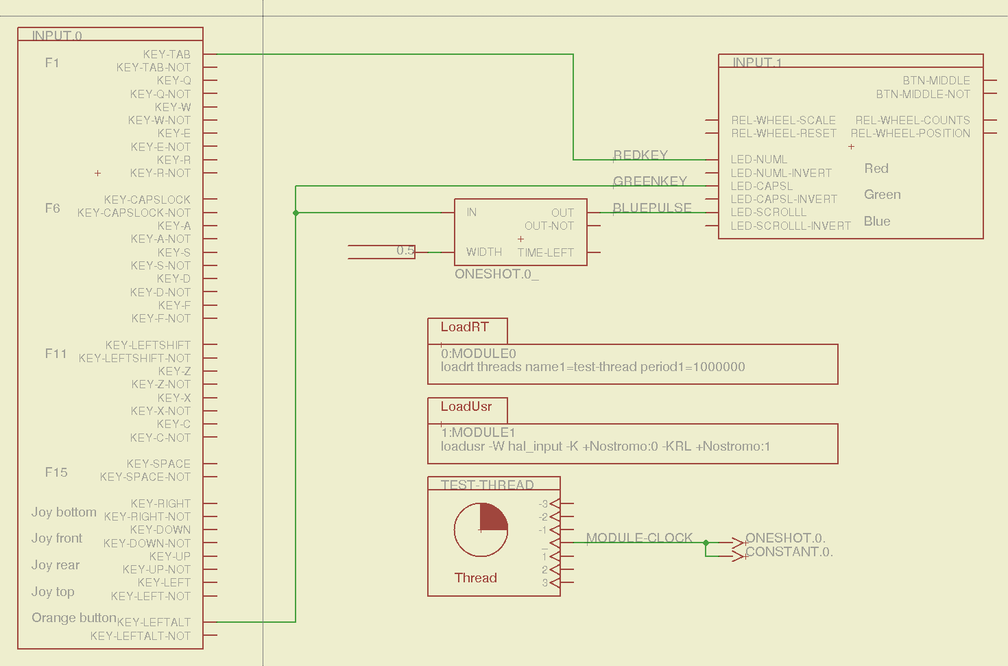
Nostromo N52 Controller – HAL config
The F01 key lights the red LED, the Orange Button lights the green LED, and a oneshot timer pulses the blue LED for half a second after the Button closes. The Thread block defines the connections from the functions to the main timing routine, and the loadrt block defines the thread timing. The hal_input module takes care of its own input sampling in userspace.
Now, for the classic embedded system “Hello, world!” test:
Nostromo N52 Controller – F01 test
It’s amazing how good an LED can make you feel…
A halscope shot shows the timing relation between the Orange Button (confusingly hitched to the greenkey signal) and the oneshot pulse:
HalScope – oneshot triggering
That schematic produces this HAL configuration file:
# HAL config file automatically generated by Eagle-CAD ULP:
# [/mnt/bulkdata/Project Files/eagle/ulp/hal-write-2.5.ulp]
# (C) Martin Schoeneck.de 2008
# Charalampos Alexopoulos 2011
# Mods Ed Nisley KE4ZNU 2010 2013
# Path        [/mnt/bulkdata/Project Files/eagle/projects/LinuxCNC HAL Configuration/]
# ProjectName [Nostromo]
# File name   [/mnt/bulkdata/Project Files/eagle/projects/LinuxCNC HAL Configuration/Nostromo.hal]
# Created     [12:28:04 14-Feb-2013]

####################################################
# Load realtime and userspace modules
loadrt threads name1=test-thread period1=1000000
loadusr -W hal_input -K +Nostromo:0 -KRL +Nostromo:1
loadrt constant		count=1
loadrt oneshot		count=1

####################################################
# Hook functions into threads
addf oneshot.0		test-thread
addf constant.0		test-thread

####################################################
# Set parameters

####################################################
# Set constants
setp constant.0.value	0.5

####################################################
# Connect Modules with nets
net bluepulse input.1.led-scrolll oneshot.0.out
net duration constant.0.out oneshot.0.width
net greenkey input.0.key-leftalt oneshot.0.in input.1.led-capsl
net redkey input.0.key-tab input.1.led-numl
A snapshot of the Nostromo.sch, Nostromo.hal, hal_config.lbr, and hal-write-2.5.ulp files is in Nostromo-N52.zip.odt. Rename it to get rid of the ODT suffix, unzip it, and there you go.
While pondering whether I should use the carcass of an old Dell PC to house the stepper drivers and control logic for the LinuxCNC M2 project, I bandsawed a scrap of aluminum sheet to about the right size. It had some truly nasty gouges and bonded-on crud, so I chucked up a wire brush cup in the drill press and had at it:
Machine jeweled baseplate
It’s obvious I haven’t done jeweling in a long time, isn’t it? Even a crude engine jeweling job spiffs things right up, though, even if a cough showcase job like this deserves straighter lines and more precise spacing. The aluminum sheet is far too large for the Sherline, which put CNC right out of consideration, and I’m not up for sufficient crank spinning on the big manual mill.
I match-marked mounting holes directly from the harvested motherboard and drilled them, whereupon I discovered that the aluminum is a dead-soft gummy alloy that doesn’t machine cleanly: it won’t become the final baseplate.
Memo to Self: Use the shop vacuum with the nozzle spinward of the brush, fool.
A (formerly Belkin, now Razer, which is evidently unrelated to Mazer Rackham) Nostromo N52 SpeedPad might not be a perfect CNC pendant, but it does have plenty of buttons and an (oddly oriented) XY joypad that might be useful for, say, a 3D printer controller running LinuxCNC.
Belkin Nostromo N52 SpeedPad
Following the same path as with the Logitech Dual Action Gamepad that became the Joggy Thing, we find that the N52 reports itself as a keyboard and a mouse:
udevadm info --query=all --attribute-walk --name=/dev/bus/usb/002/004

Udevadm info starts with the device specified by the devpath and then
walks up the chain of parent devices. It prints for every device
found, all possible attributes in the udev rules key format.
A rule to match, can be composed by the attributes of the device
and the attributes from one single parent device.

  looking at device '/devices/pci0000:00/0000:00:02.0/usb2/2-10':
    KERNEL=="2-10"
    SUBSYSTEM=="usb"
    DRIVER=="usb"
    ATTR{configuration}==""
    ATTR{bNumInterfaces}==" 2"
    ATTR{bConfigurationValue}=="1"
    ATTR{bmAttributes}=="80"
    ATTR{bMaxPower}==" 90mA"
    ATTR{urbnum}=="1354"
    ATTR{idVendor}=="050d"
    ATTR{idProduct}=="0815"
    ATTR{bcdDevice}=="0210"
    ATTR{bDeviceClass}=="00"
    ATTR{bDeviceSubClass}=="00"
    ATTR{bDeviceProtocol}=="00"
    ATTR{bNumConfigurations}=="1"
    ATTR{bMaxPacketSize0}=="8"
    ATTR{speed}=="1.5"
    ATTR{busnum}=="2"
    ATTR{devnum}=="4"
    ATTR{version}==" 1.10"
    ATTR{maxchild}=="0"
    ATTR{quirks}=="0x0"
    ATTR{authorized}=="1"
    ATTR{manufacturer}=="Honey Bee "
    ATTR{product}=="Nostromo SpeedPad2 "

... snippage ...
Note the trailing blank in the manufacturer and product values.
Create a new rules file /etc/udev/rule/90-Nostromo.rules to change the group and permissions:
# Belkin Nostromo N52 SpeedPad controller for LinuxCNC
# Ed Nisley - KE4ZNU - February 2013

ATTRS{product}=="Nostromo SpeedPad2",GROUP="plugdev",MODE="0660"
Note that the file name must start with a number around 90- to avoid being clobbered by a rule in /lib/udev/rules.d/50-udev-default.rules that (re)sets the permissions to 0640; the doc suggests that rules without numbers happen after all the number rules, so perhaps you could just use meaningful names. That took an embarrassingly long time to figure out…
There’s no need for the trailing blank in that rule, as the match proceeds left-to-right and stops at the end of the test string.
You must, perforce, be in the plugdev group. If not, add yourself.
You need not unplug the N52 to test the rule. Just use:
The + prefix tells HAL to capture the named device and prevent its events from reaching X. The KRL codes suggest which functions you’re interested in for that particular device. The suffix digit selects successive devices for multiple gadgets matching the same name string.
Apparently, the N52 reports it can produce all the usual keyboard and mouse values & buttons, even if they’re not connected to physical hardware. I suspect it has generic keyboard / mouse controllers inside, with just a few of the usual matrix crosspoints connected to switches.
The basic key mapping, sorted by the Nostromo functions:
Type
Dir
Name
Nostromo key
bit
OUT
input.0.key-tab
F1
bit
OUT
input.0.key-q
F2
bit
OUT
input.0.key-w
F3
bit
OUT
input.0.key-e
F4
bit
OUT
input.0.key-r
F5
bit
OUT
input.0.key-capslock
F6
bit
OUT
input.0.key-a
F7
bit
OUT
input.0.key-s
F8
bit
OUT
input.0.key-d
F9
bit
OUT
input.0.key-f
F10
bit
OUT
input.0.key-leftshift
F11
bit
OUT
input.0.key-z
F12
bit
OUT
input.0.key-x
F13
bit
OUT
input.0.key-c
F14
bit
OUT
input.0.key-space
F15
bit
OUT
input.0.key-leftalt
Orange button
bit
OUT
input.0.key-right
Pad bottom
bit
OUT
input.0.key-down
Pad front
bit
OUT
input.0.key-up
Pad rear
bit
OUT
input.0.key-left
Pad top
bit
OUT
input.1.btn-middle
Wheel press
s32
OUT
input.1.rel-wheel-counts
Scroll wheel
bit
IN
input.1.led-numl
Red LED
bit
IN
input.1.led-capsl
Green LED
bit
IN
input.1.led-scrolll
Blue LED
The bit pins also have inverted values available on the corresponding -not pins. The LEDs have an -invert that flips the sense of the input pin. The rel-wheel pin has other useful tidbits as suffixes; the count changes by ±1 for each wheel detent.
The Tab key and all the letters auto-repeat, the various Shift and Alt keys do not. That seems to make no difference to the bit values reported by HAL.
That doesn’t verify that you can successfully create a bazillion little files, but it’s a good rough-and-ready check that you haven’t gotten, say, a 2 GB drive mis-labeled as 4 GB. It could happen…
Assuming you’ve deleted any shovelware (these were clean) and that the drives are now empty (as these were), find out how big they claim to be:
df /media/ed/CENTON\ USB/
Filesystem     1K-blocks  Used Available Use% Mounted on
/dev/sdb1        4107284     4   4107280   1% /media/ed/CENTON USB
Pour /dev/urandom into a file that will fill the available space (not the total space), which will take several minutes:
time dd bs=1K count=4107280 if=/dev/urandom of=/tmp/test.dat
4107280+0 records in
4107280+0 records out
4205854720 bytes (4.2 GB) copied, 450.883 s, 9.3 MB/s

real	7m31.162s
user	0m0.712s
sys	6m54.166s
Copy it to the drive, using rsync with a progress indicator:
time rsync --progress /tmp/test.dat /media/ed/CENTON\ USB/
test.dat
  4205854720 100%    8.45MB/s    0:07:54 (xfer#1, to-check=0/1)

sent 4206368202 bytes  received 31 bytes  8772405.07 bytes/sec
total size is 4205854720  speedup is 1.00

real	7m59.035s
user	0m24.490s
sys	0m17.433s
Verify that the two files match:
time diff /tmp/test.dat /media/ed/CENTON\ USB
real	3m32.576s
user	0m0.588s
sys	0m6.268s
And, yes, one of them is noticeably darker; four of the others seem lighter and five darker gray. Most likely, the cases came from three different anodizing batches and, I suppose, if I were to pry them apart, the innards could be radically different. Ya never know!
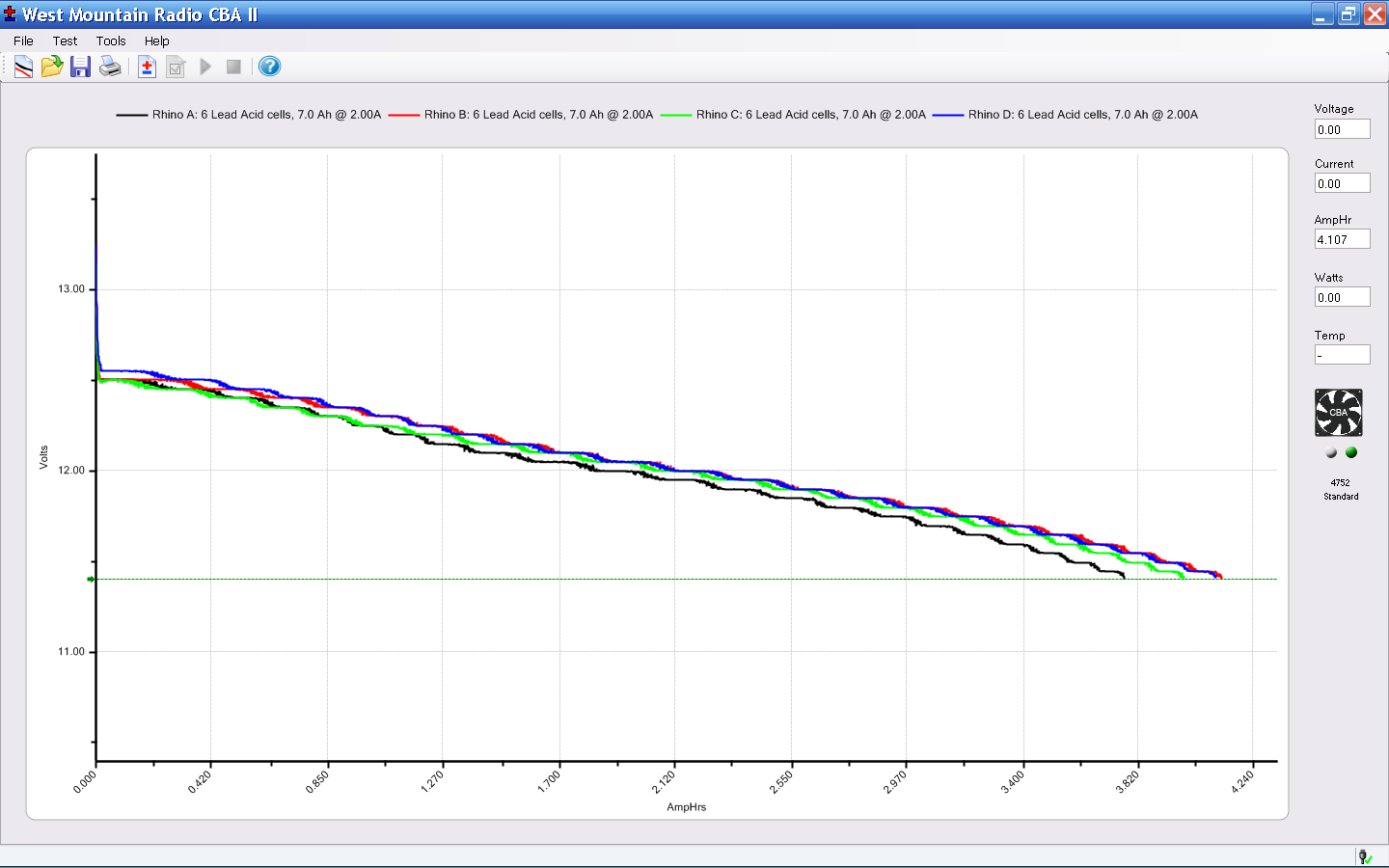
Just got a quartet of 12 V 7 A·h lead batteries, prompted by a big Belkin UPS that instantly shut down during a power blink. It needs only two batteries, but the shipping was the same for two or four and I’m sure the spares will come in handy.
A stiff 2 A discharge test shows that SLA batteries really don’t like high currents, which is exactly what they must provide in a UPS:
Rhino SLA – 2013-01
The capacity is barely 4 A·h at 2 A, not to mention that I’m using a conservative 11.4 V cutoff.
The two batteries with the highest capacity also were the closest matches, so they’re now in the UPS.
As nearly as I can tell, Epson designed a number of features into the R380 specifically to thwart CISS installation, including the awkward bridge across the middle of the printer that interferes with the flat tube feeding ink to the flying cartridges. I managed to route the previous CISS tubing around the bridge, but this time I figured enough was enough.
So I tucked a shop rag inside the printer, put a vacuum cleaner nozzle near the operation, and applied a fine-tooth pull saw to the bridge:
Epson R380 – bridge removed
That certainly simplified the rest of the installation…
Mary gave a gardening presentation at the local library, popping a 4 GB USB memory stick with the presentation into a library computer connected to the display projector. Back home, she deleted the presentations and was about to add more files, when she noticed something interesting:
drwx------  4 ed   ed    4096 Dec 31  1969 ./
drwxr-x---+ 3 root root  4096 Jan 31 19:21 ../
-r--r--r--  1 ed   ed   59288 Mar 21  2009 autorun.inf
drwx------  3 ed   ed    4096 Jan 30 19:31 RECYCLER/
drwx------  4 ed   ed    4096 Jan 31 19:10 .Trash-1001/
Ubuntu 12.10 automagically mounts FAT filesystems with the current user as owner and group. The .Trash-1001 directory is the Linux trash heap, but where did all that other stuff come from? The autorun.inf definitely looks Window-y, doesn’t it?
Perforce, the library runs Windows, but that shouldn’t add files to a USB memory stick that just was plugged in and used for a read-only presentation, should it?
Huh. You know where this is going…
Let’s hand autorun.inf to VirusTotal for a second opinion. The first three results from their long list confirm my suspicion:
Antivirus
Result
Update
Agnitum
INF.Conficker.F
20130131
AhnLab-V3
Win32/Conficker.worm
20130131
AntiVir
Worm/Kido.IH.40
20130131
The executable file containing the actual payload is, of course, buried in a subdirectory that might look more innocent on a Windows box: /RECYCLER/S-5-3-42-2819952290-8240758988-879315005-3665/
It sports a randomized name to evade a really stupid malware detector: jwgkvsq.vmx
Here’s what VirusTotal reports from some heavy hitters in the AV field:
Kaspersky
Net-Worm.Win32.Kido.ih
20130131
Kingsoft
Worm.Kido.ih.(kcloud)
20130131
Malwarebytes
Worm.Conficker
20130131
McAfee
W32/Conficker.worm
20130201
McAfee-GW-Edition
W32/Conficker.worm
20130131
Microsoft
Worm:Win32/Conficker.B
20130131
The Wikipedia article gives the details. I suppose that PC got it from somebody else’s USB stick, but the library really should be running some defensive software; Conficker dates back to 2008, so it’s not new news these days.
That kind of Windows Genuine Advantage makes up for all the hassles of running Linux, right there. Mary reported the problem to the library; we’ll never know the rest of the story.