Ed Nisley's Blog: Shop notes, electronics, firmware, machinery, 3D printing, laser cuttery, and curiosities. Contents: 100% human thinking, 0% AI slop.
Because it seems there’s no good support for separate X sessions with dual monitors these days, the landscape and portrait monitors on my desk represent viewports into a larger pixel array within a single X session. As a consequence, it’s entirely possible to slide windows across the gutter between the two displays (generally producing an essentially unusable result), but one cannot flip through workspaces on only one monitor.
Worse, some programs seem to have trouble remembering that they were last seen on the portrait monitor, so I must rearrange the windows at the start of every session. First world problem, yeah, but still annoying.
I’d previously used devilspie to force windows to their proper places across monitors, sessions, and workspaces, but its s-expression syntax was impenetrable and I eventually gave up using it.
A fork (or continuation or something) called devilspie2 uses lua scripts that I can both read and write. It’s an Ubuntu package and easy to set up.
A typical script in ~/.config/devilspie2 looks like this:
if (get_application_name()=="Firefox") then
   set_window_geometry(0,0,1300,1200);
   maximize_vertically();
end
Putting Adobe Reader on the portrait monitor looks about the same:
if (get_application_name()=="acroread") then
   unmaximize();
   set_window_geometry(2561,0,1000,100);
   maximize();
end
Set /usr/bin/devilspie2 as an auto-started program and it Just Works…
The problem was to get both a landscape and a portrait monitor working. The complexity came from the landscape monitor, a 2560×1440 Dell U2711, which requires either a Dual-Link DVI or HDMI input to reach full resolution. The portrait monitor, an old 1608×1050 Dell 2005FPW, uses Single-Link DVI.
The previous attempt with an nVidia GT430 card failed: both DVI outputs were Single-Link, despite their connector’s appearance. It had worked OK with the previous landscape monitor, a 1600×1200 Dell 2001FP.
So I picked up a low-end nVidia GT610 card that advertised both Dual-Link DVI and HDMI. I plugged the DVI cable into the U2711 and it lit up at full resolution, then I plugged the HDMI into the 2005FPW and it lit right up. By some miracle that didn’t involve tweaking an xorg.conf file, the 2005FPW immediately displayed the pixels lying to the right of the U2711, exactly as I wanted; all I had to do was rotate the image using xrandr.
Not only that, but the version of xsetwacom in Xubuntu 12.10 once again respects the MapToOutput "HEAD-0" option that restricts the stylus to the U2711 monitor. That means I can’t put the GIMP toolbars and suchlike on the portrait monitor, but the U2711 has enough dots to render that moot.
Although the Dell doc strongly suggests that the on-board VGA and Displayport outputs don’t work with a PCI-E video card plugged in, xrandr reports:
Screen 0: minimum 8 x 8, current 3610 x 1680, maximum 16384 x 16384
DVI-I-0 disconnected (normal left inverted right x axis y axis)
VGA-0 disconnected (normal left inverted right x axis y axis)
DVI-I-1 connected 2560x1440+0+0 (normal left inverted right x axis y axis) 597mm x 336mm
   2560x1440      60.0*+
   1920x1200      59.9
   1680x1050      60.0
   1600x1200      60.0
   1280x1024      75.0     60.0
   1280x800       59.8
   1152x864       75.0
   1024x768       75.0     60.0
   800x600        75.0     60.3
   640x480        75.0     59.9
HDMI-0 connected 1050x1680+2560+0 left (normal left inverted right x axis y axis) 434mm x 270mm
   1680x1050      59.9*+
   1280x1024      75.0     60.0
   1152x864       75.0
   1024x768       75.0     60.0
   800x600        75.0     60.3
   640x480        75.0     59.9
I’m not going to connect the DVI-I-0 and VGA-0 outputs; my physical desk has no room for more pixels…
The ~/.xprofile file now looks like:
setxkbmap -option terminate:ctrl_alt_bksp
xrandr --output HDMI-0 --rotate left
xrandr --dpi 100x100
xsetwacom --verbose set "Wacom Graphire3 6x8 stylus" MapToOutput "HEAD-0"
xsetwacom --verbose set "Wacom Graphire3 6x8 eraser" MapToOutput "HEAD-0"
That comment suggested scroll ring failures on a Kensington Expert Mouse (it’s a trackball) might occur when the apertures become misaligned from the IR emitter-detector pair, although later results were equivocal. I tore apart a failed unit to see what the alignment looked like for a known-bad scroll ring.
The right side view shows the receiver roughly centered in an aperture:
Kensington Expert Mouse – Scroll Ring aperture – right
The left side view shows that the ring is almost flush against the circuit board, with the isolating cutout just in front, and it’s not obvious how to lower it any further:
Kensington Expert Mouse – Scroll Ring aperture – left
So I think there’s no way to realign this one, other than to raise the aperture ring a bit, but that doesn’t seem like it would make any difference: the detector already has a good view of the emitter.
If your trackball has a failed scroll ring, tweaking the aperture ring’s alignment certainly can’t hurt: try it and report back.
If you don’t expect a miracle, you probably won’t be disappointed, alas.
Hi, I wanted to leave a comment for your page here: [this url]
I’ve got an expert mouse trackball that was having intermittent scroll ring problems, then finally quit working altogether. Dismantled it easily using the instructions on this site.
Cleaned it and it still wasn’t working. Tried changing the alignment of the IR emitter/detectors and it still wasn’t working. Then we kept on fiddling with the alignment and voilà.
Like others have said, the alignment seems to be SUPER sensitive. So if any others are reading this with the same problem, keep persevering.
Thanks to everyone who has posted to help find solutions!
That comment suggested a different solution to the problem of having the display manager start before the NFS mounts complete. When that happens, you can sign in and start programs that won’t have access to their data, producing all manner of heartache and confusion.
One complication: it seems /etc/rc.local starts and runs before the network (among other tidbits) gets connected and becomes ready, which means you can’t just plunk your code in that file like you used to, at least not in Ubuntu. Fixing that requires an upstart script triggered when the network interface finally hauls itself to its feet.
There’s no actual link between the NFS mount commands and the display manager startup, but it seems that if you don’t attempt to mount the NFS shares before the network becomes active (which is what happen with shares automounted through /etc/fstab), but wait for the network to come up and then issue the mounts, the shares mount almost instantly and become ready by the time the display manager presents the login screen. That’s better than the kludge I had figured out and works fine, so I’ll run with it until something else breaks.
The not-quite-deterministic fix has three parts:
Use noauto in the fstab entries for the NFS shares
Create an upstart script to mount those shares after eth0 lights up
Allow lightdm to start up normally (i.e., remove my hackish attempts)
A sample line from fstab, with the vital noauto option:
The /etc/init/local.conf script assumes the network interface will be eth0, which does not generalize to wireless networks on laptops and suchlike. You could add some Boolean logic to wait for the first of several interfaces, I suppose:
description "Stuff that should be in /etc/rc.local"
author "Ed Nisley - KE4ZNU"

start on (local-filesystems and net-device-up IFACE=eth0)
stop on shutdown
script

logger Starting local init...

logger Mounting NFS filesystems
mount /mnt/bulkdata
mount /mnt/userfiles
mount /mnt/diskimages
mount /mnt/music

logger Ending local init

end script
The lightdm.conf file reverts to the distribution version, with this starting trigger:
start on ((filesystem
           and runlevel [!06]
           and started dbus
           and (drm-device-added card0 PRIMARY_DEVICE_FOR_DISPLAY=1
                or stopped udev-fallback-graphics))
          or runlevel PREVLEVEL=S)
It’s worth noting that the upstart interpreter hates comment lines embedded within statements: it does not regard them as whitespace and does not ignore them. Just don’t do it. That explains some of the problems I encountered before, but fixing those problems did not eliminate the overall issue.
The end result of all that hocus-pocus makes the box boot the way it used to: the display manager comes up promptly, presents the GUI login screen, and the NFS mounts are ready when you are.
This is not made obvious at the outset, but a video card with a DMS-59 connector that can drive a pair of Single Link DVI monitors cannot drive a single Dual Link DVI monitor: the DMS-59 connector doesn’t have the required signals.
The fact that each of the Single Link DVI connectors on the end of the DMS-59 Y-splitter cable have enough pins (well, holes) to mate with a Dual Link DVI cable doesn’t clarify the situation.
Of course, you can’t combine two separate Single Link outputs into a Dual Link input.
An HDMI 1.4 cable can support a single 2560×1440 monitor, but not from this resolutely low-res video card.
Bus 005 Device 001: ID 1d6b:0001 Linux Foundation 1.1 root hub
Bus 004 Device 006: ID 06f2:0011 Emine Technology Co. KVM Switch Keyboard
Bus 004 Device 005: ID 046d:c401 Logitech, Inc. TrackMan Marble Wheel
Bus 004 Device 004: ID 04d9:1203 Holtek Semiconductor, Inc. MC Industries Keyboard
Bus 004 Device 003: ID 046d:c216 Logitech, Inc. Dual Action Gamepad
Bus 004 Device 002: ID 0451:2046 Texas Instruments, Inc. TUSB2046 Hub
Bus 004 Device 001: ID 1d6b:0001 Linux Foundation 1.1 root hub
Bus 003 Device 001: ID 1d6b:0001 Linux Foundation 1.1 root hub
Bus 002 Device 002: ID 2341:8036
Bus 002 Device 001: ID 1d6b:0001 Linux Foundation 1.1 root hub
Bus 001 Device 001: ID 1d6b:0002 Linux Foundation 2.0 root hub
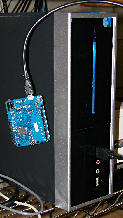
For whatever reason, this board doesn’t report a device name. It’s plugged into the same USB port as that mouse, so it gets the same Bus and Device numbers, which helps confirm that’s the board.
Querying the attributes with udevadm produces the all-important product string:
halrun
halcmd: loadusr -W hal_input -KRAL Leo
halcmd: show all
Loaded HAL Components:
ID      Type  Name                                      PID   State
     5  User  hal_input                                 11265 ready
     3  User  halcmd11264                               11264 ready

Component Pins:
Owner   Type  Dir         Value  Name
     5  bit   OUT         FALSE  input.0.btn-middle
     5  bit   OUT          TRUE  input.0.btn-middle-not
     5  bit   OUT         FALSE  input.0.btn-mouse
     5  bit   OUT          TRUE  input.0.btn-mouse-not
     5  bit   OUT         FALSE  input.0.btn-right
     5  bit   OUT          TRUE  input.0.btn-right-not
     5  bit   OUT         FALSE  input.0.key-0
     5  bit   OUT          TRUE  input.0.key-0-not
     5  bit   OUT         FALSE  input.0.key-1
     5  bit   OUT          TRUE  input.0.key-1-not
     5  bit   OUT         FALSE  input.0.key-102nd
     5  bit   OUT          TRUE  input.0.key-102nd-not
     5  bit   OUT         FALSE  input.0.key-2
     5  bit   OUT          TRUE  input.0.key-2-not
     5  bit   OUT         FALSE  input.0.key-3
     5  bit   OUT          TRUE  input.0.key-3-not
     5  bit   OUT         FALSE  input.0.key-4
     5  bit   OUT          TRUE  input.0.key-4-not
     5  bit   OUT         FALSE  input.0.key-5
     5  bit   OUT          TRUE  input.0.key-5-not
     5  bit   OUT         FALSE  input.0.key-6
     5  bit   OUT          TRUE  input.0.key-6-not
     5  bit   OUT         FALSE  input.0.key-7
     5  bit   OUT          TRUE  input.0.key-7-not
     5  bit   OUT         FALSE  input.0.key-8
     5  bit   OUT          TRUE  input.0.key-8-not
     5  bit   OUT         FALSE  input.0.key-9
     5  bit   OUT          TRUE  input.0.key-9-not
     5  bit   OUT         FALSE  input.0.key-a
     5  bit   OUT          TRUE  input.0.key-a-not
     5  bit   OUT         FALSE  input.0.key-apostrophe
     5  bit   OUT          TRUE  input.0.key-apostrophe-not
     5  bit   OUT         FALSE  input.0.key-b
     5  bit   OUT          TRUE  input.0.key-b-not
     5  bit   OUT         FALSE  input.0.key-backslash
     5  bit   OUT          TRUE  input.0.key-backslash-not
     5  bit   OUT         FALSE  input.0.key-backspace
     5  bit   OUT          TRUE  input.0.key-backspace-not
     5  bit   OUT         FALSE  input.0.key-c
     5  bit   OUT          TRUE  input.0.key-c-not
     5  bit   OUT         FALSE  input.0.key-capslock
     5  bit   OUT          TRUE  input.0.key-capslock-not
     5  bit   OUT         FALSE  input.0.key-comma
     5  bit   OUT          TRUE  input.0.key-comma-not
     5  bit   OUT         FALSE  input.0.key-compose
     5  bit   OUT          TRUE  input.0.key-compose-not
     5  bit   OUT         FALSE  input.0.key-d
     5  bit   OUT          TRUE  input.0.key-d-not
     5  bit   OUT         FALSE  input.0.key-delete
     5  bit   OUT          TRUE  input.0.key-delete-not
     5  bit   OUT         FALSE  input.0.key-dot
     5  bit   OUT          TRUE  input.0.key-dot-not
     5  bit   OUT         FALSE  input.0.key-down
     5  bit   OUT          TRUE  input.0.key-down-not
     5  bit   OUT         FALSE  input.0.key-e
     5  bit   OUT          TRUE  input.0.key-e-not
     5  bit   OUT         FALSE  input.0.key-end
     5  bit   OUT          TRUE  input.0.key-end-not
     5  bit   OUT         FALSE  input.0.key-enter
     5  bit   OUT          TRUE  input.0.key-enter-not
     5  bit   OUT         FALSE  input.0.key-equal
     5  bit   OUT          TRUE  input.0.key-equal-not
     5  bit   OUT         FALSE  input.0.key-esc
     5  bit   OUT          TRUE  input.0.key-esc-not
     5  bit   OUT         FALSE  input.0.key-f
     5  bit   OUT          TRUE  input.0.key-f-not
     5  bit   OUT         FALSE  input.0.key-f1
     5  bit   OUT          TRUE  input.0.key-f1-not
     5  bit   OUT         FALSE  input.0.key-f10
     5  bit   OUT          TRUE  input.0.key-f10-not
     5  bit   OUT         FALSE  input.0.key-f11
     5  bit   OUT          TRUE  input.0.key-f11-not
     5  bit   OUT         FALSE  input.0.key-f12
     5  bit   OUT          TRUE  input.0.key-f12-not
     5  bit   OUT         FALSE  input.0.key-f2
     5  bit   OUT          TRUE  input.0.key-f2-not
     5  bit   OUT         FALSE  input.0.key-f3
     5  bit   OUT          TRUE  input.0.key-f3-not
     5  bit   OUT         FALSE  input.0.key-f4
     5  bit   OUT          TRUE  input.0.key-f4-not
     5  bit   OUT         FALSE  input.0.key-f5
     5  bit   OUT          TRUE  input.0.key-f5-not
     5  bit   OUT         FALSE  input.0.key-f6
     5  bit   OUT          TRUE  input.0.key-f6-not
     5  bit   OUT         FALSE  input.0.key-f7
     5  bit   OUT          TRUE  input.0.key-f7-not
     5  bit   OUT         FALSE  input.0.key-f8
     5  bit   OUT          TRUE  input.0.key-f8-not
     5  bit   OUT         FALSE  input.0.key-f9
     5  bit   OUT          TRUE  input.0.key-f9-not
     5  bit   OUT         FALSE  input.0.key-g
     5  bit   OUT          TRUE  input.0.key-g-not
     5  bit   OUT         FALSE  input.0.key-grave
     5  bit   OUT          TRUE  input.0.key-grave-not
     5  bit   OUT         FALSE  input.0.key-h
     5  bit   OUT          TRUE  input.0.key-h-not
     5  bit   OUT         FALSE  input.0.key-home
     5  bit   OUT          TRUE  input.0.key-home-not
     5  bit   OUT         FALSE  input.0.key-i
     5  bit   OUT          TRUE  input.0.key-i-not
     5  bit   OUT         FALSE  input.0.key-insert
     5  bit   OUT          TRUE  input.0.key-insert-not
     5  bit   OUT         FALSE  input.0.key-j
     5  bit   OUT          TRUE  input.0.key-j-not
     5  bit   OUT         FALSE  input.0.key-k
     5  bit   OUT          TRUE  input.0.key-k-not
     5  bit   OUT         FALSE  input.0.key-kp0
     5  bit   OUT          TRUE  input.0.key-kp0-not
     5  bit   OUT         FALSE  input.0.key-kp1
     5  bit   OUT          TRUE  input.0.key-kp1-not
     5  bit   OUT         FALSE  input.0.key-kp2
     5  bit   OUT          TRUE  input.0.key-kp2-not
     5  bit   OUT         FALSE  input.0.key-kp3
     5  bit   OUT          TRUE  input.0.key-kp3-not
     5  bit   OUT         FALSE  input.0.key-kp4
     5  bit   OUT          TRUE  input.0.key-kp4-not
     5  bit   OUT         FALSE  input.0.key-kp5
     5  bit   OUT          TRUE  input.0.key-kp5-not
     5  bit   OUT         FALSE  input.0.key-kp6
     5  bit   OUT          TRUE  input.0.key-kp6-not
     5  bit   OUT         FALSE  input.0.key-kp7
     5  bit   OUT          TRUE  input.0.key-kp7-not
     5  bit   OUT         FALSE  input.0.key-kp8
     5  bit   OUT          TRUE  input.0.key-kp8-not
     5  bit   OUT         FALSE  input.0.key-kp9
     5  bit   OUT          TRUE  input.0.key-kp9-not
     5  bit   OUT         FALSE  input.0.key-kpasterisk
     5  bit   OUT          TRUE  input.0.key-kpasterisk-not
     5  bit   OUT         FALSE  input.0.key-kpdot
     5  bit   OUT          TRUE  input.0.key-kpdot-not
     5  bit   OUT         FALSE  input.0.key-kpenter
     5  bit   OUT          TRUE  input.0.key-kpenter-not
     5  bit   OUT         FALSE  input.0.key-kpminus
     5  bit   OUT          TRUE  input.0.key-kpminus-not
     5  bit   OUT         FALSE  input.0.key-kpplus
     5  bit   OUT          TRUE  input.0.key-kpplus-not
     5  bit   OUT         FALSE  input.0.key-kpslash
     5  bit   OUT          TRUE  input.0.key-kpslash-not
     5  bit   OUT         FALSE  input.0.key-l
     5  bit   OUT          TRUE  input.0.key-l-not
     5  bit   OUT         FALSE  input.0.key-left
     5  bit   OUT          TRUE  input.0.key-left-not
     5  bit   OUT         FALSE  input.0.key-leftalt
     5  bit   OUT          TRUE  input.0.key-leftalt-not
     5  bit   OUT         FALSE  input.0.key-leftbrace
     5  bit   OUT          TRUE  input.0.key-leftbrace-not
     5  bit   OUT         FALSE  input.0.key-leftctrl
     5  bit   OUT          TRUE  input.0.key-leftctrl-not
     5  bit   OUT         FALSE  input.0.key-leftmeta
     5  bit   OUT          TRUE  input.0.key-leftmeta-not
     5  bit   OUT         FALSE  input.0.key-leftshift
     5  bit   OUT          TRUE  input.0.key-leftshift-not
     5  bit   OUT         FALSE  input.0.key-m
     5  bit   OUT          TRUE  input.0.key-m-not
     5  bit   OUT         FALSE  input.0.key-minus
     5  bit   OUT          TRUE  input.0.key-minus-not
     5  bit   OUT         FALSE  input.0.key-n
     5  bit   OUT          TRUE  input.0.key-n-not
     5  bit   OUT         FALSE  input.0.key-numlock
     5  bit   OUT          TRUE  input.0.key-numlock-not
     5  bit   OUT         FALSE  input.0.key-o
     5  bit   OUT          TRUE  input.0.key-o-not
     5  bit   OUT         FALSE  input.0.key-p
     5  bit   OUT          TRUE  input.0.key-p-not
     5  bit   OUT         FALSE  input.0.key-pagedown
     5  bit   OUT          TRUE  input.0.key-pagedown-not
     5  bit   OUT         FALSE  input.0.key-pageup
     5  bit   OUT          TRUE  input.0.key-pageup-not
     5  bit   OUT         FALSE  input.0.key-pause
     5  bit   OUT          TRUE  input.0.key-pause-not
     5  bit   OUT         FALSE  input.0.key-q
     5  bit   OUT          TRUE  input.0.key-q-not
     5  bit   OUT         FALSE  input.0.key-r
     5  bit   OUT          TRUE  input.0.key-r-not
     5  bit   OUT         FALSE  input.0.key-right
     5  bit   OUT          TRUE  input.0.key-right-not
     5  bit   OUT         FALSE  input.0.key-rightalt
     5  bit   OUT          TRUE  input.0.key-rightalt-not
     5  bit   OUT         FALSE  input.0.key-rightbrace
     5  bit   OUT          TRUE  input.0.key-rightbrace-not
     5  bit   OUT         FALSE  input.0.key-rightctrl
     5  bit   OUT          TRUE  input.0.key-rightctrl-not
     5  bit   OUT         FALSE  input.0.key-rightmeta
     5  bit   OUT          TRUE  input.0.key-rightmeta-not
     5  bit   OUT         FALSE  input.0.key-rightshift
     5  bit   OUT          TRUE  input.0.key-rightshift-not
     5  bit   OUT         FALSE  input.0.key-s
     5  bit   OUT          TRUE  input.0.key-s-not
     5  bit   OUT         FALSE  input.0.key-scrolllock
     5  bit   OUT          TRUE  input.0.key-scrolllock-not
     5  bit   OUT         FALSE  input.0.key-semicolon
     5  bit   OUT          TRUE  input.0.key-semicolon-not
     5  bit   OUT         FALSE  input.0.key-slash
     5  bit   OUT          TRUE  input.0.key-slash-not
     5  bit   OUT         FALSE  input.0.key-space
     5  bit   OUT          TRUE  input.0.key-space-not
     5  bit   OUT         FALSE  input.0.key-sysrq
     5  bit   OUT          TRUE  input.0.key-sysrq-not
     5  bit   OUT         FALSE  input.0.key-t
     5  bit   OUT          TRUE  input.0.key-t-not
     5  bit   OUT         FALSE  input.0.key-tab
     5  bit   OUT          TRUE  input.0.key-tab-not
     5  bit   OUT         FALSE  input.0.key-u
     5  bit   OUT          TRUE  input.0.key-u-not
     5  bit   OUT         FALSE  input.0.key-up
     5  bit   OUT          TRUE  input.0.key-up-not
     5  bit   OUT         FALSE  input.0.key-v
     5  bit   OUT          TRUE  input.0.key-v-not
     5  bit   OUT         FALSE  input.0.key-w
     5  bit   OUT          TRUE  input.0.key-w-not
     5  bit   OUT         FALSE  input.0.key-x
     5  bit   OUT          TRUE  input.0.key-x-not
     5  bit   OUT         FALSE  input.0.key-y
     5  bit   OUT          TRUE  input.0.key-y-not
     5  bit   OUT         FALSE  input.0.key-z
     5  bit   OUT          TRUE  input.0.key-z-not
     5  s32   OUT             0  input.0.rel-wheel-counts
     5  float OUT             0  input.0.rel-wheel-position
     5  bit   IN          FALSE  input.0.rel-wheel-reset
     5  float IN              1  input.0.rel-wheel-scale
     5  s32   OUT             0  input.0.rel-x-counts
     5  float OUT             0  input.0.rel-x-position
     5  bit   IN          FALSE  input.0.rel-x-reset
     5  float IN              1  input.0.rel-x-scale
     5  s32   OUT             0  input.0.rel-y-counts
     5  float OUT             0  input.0.rel-y-position
     5  bit   IN          FALSE  input.0.rel-y-reset
     5  float IN              1  input.0.rel-y-scale
That’s a pretty decent assortment of directly usable names and features, even without keyboard LEDs. The mouse pins could be repurposed for general sensor values:
position = float = count / scale (why divided? I don’t know)
scale = float = turns counts into position
reset = bit = resets position or maybe count (not sure)
I think you could use count to transfer a bare ADC reading from the Leonardo, then use scale to get the actual voltage in “position”. In that situation, reset wouldn’t be at all useful.
The keyboard pins could transfer Boolean sensors.
You’d want to give HAL exclusive control of the Leonardo-is-not-a-mouse, because the incoming data would make hash of the, ah, LinuxCNC UI experience in short order. I’m not sure how to control that; the Leonardo advice boils down to “be careful” and “use a physical switch”.
I have *no* idea where the names come from, but apparently the OS / kernel / something has a HID layer that translates bare USB capability bits into strings. How that relates to a particular device, what the choices might be, how one could add / replace the names for a given device, and all that, I don’t know yet.
The hack I added to the lightdm startup script occasionally causes it to hang, which suggests a timing problem. The result leaves the default text-mode login screen active on VT1, after which I can log in and issue sudo lightdm start to produce the usual GUI screen. Using startx doesn’t (seem to) start the display manager, resulting in all manner of weird behavior.
start on ((filesystem
           and runlevel [!06]
           and started dbus
           and (drm-device-added card0 PRIMARY_DEVICE_FOR_DISPLAY=1
                or stopped udev-fallback-graphics)
           and mounted MOUNTPOINT=/mnt/bulkdata)
          or runlevel PREVLEVEL=S)
According to the timing diagram in section 10.1.8, the filesystem event should happen after all the remote filesystems have been mounted, which seems like that stanza might produce a race condition. So just waiting for the filesystem event should suffice, but it doesn’t; that’s why I had to add the mounted event.
According to the example in section 11.14, that stanza should probably look like:
start on ((filesystem
           and (runlevel [!06]
           and (started dbus
           and (drm-device-added card0 PRIMARY_DEVICE_FOR_DISPLAY=1
                or stopped udev-fallback-graphics))))
          or runlevel PREVLEVEL=S)
The additional parentheses around successive conditions seem to serialize them, so that they need not all occur at the same time.
At least I think that’s how it should work…
Unfortunately, it doesn’t. The good news is that it’s converted the intermittent failure into a hard fault, which is generally a step in the right direction.
Changing the stanza to:
#start on ((filesystem
start on ((mounted MOUNTPOINT=/mnt/bulkdata
           and runlevel [!06]
           and started dbus
           and (drm-device-added card0 PRIMARY_DEVICE_FOR_DISPLAY=1
                or stopped udev-fallback-graphics))
#           and mounted MOUNTPOINT=/mnt/bulkdata))
          or runlevel PREVLEVEL=S)
… also fails hard.
At this point, I have no idea what to do, so I’ve restored the original stanza.