Ed Nisley's Blog: Shop notes, electronics, firmware, machinery, 3D printing, laser cuttery, and curiosities. Contents: 100% human thinking, 0% AI slop.
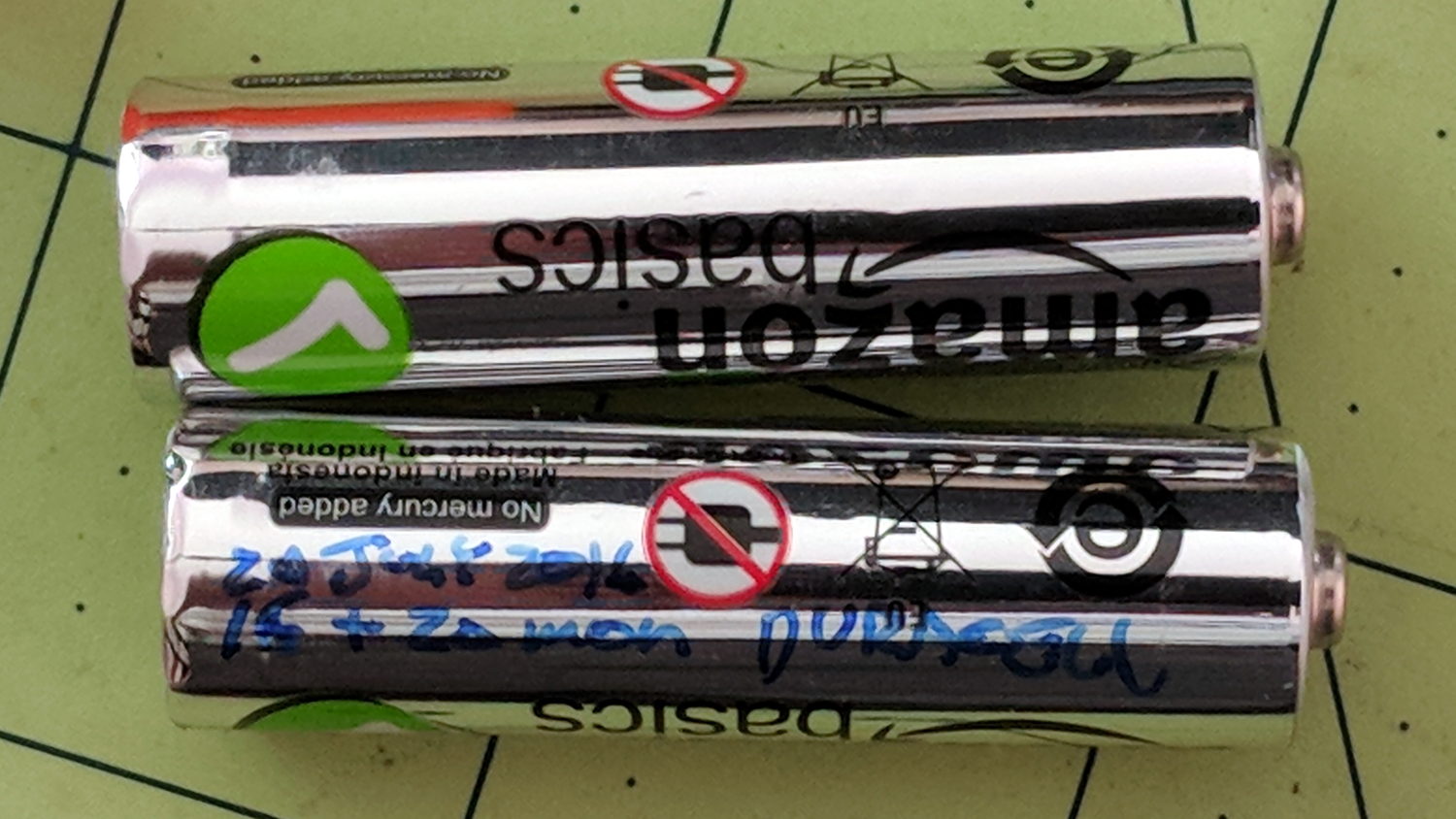
Being that sort of bear, I (sometimes) note the date on cells when I change them, as with this notation on the AA alkaline cells in the Logitech trackball:
Amazon Basics AA cell – mouse runtime
These Amazon Basics AA cells lasted almost exactly two years, compared with 15 and 20 months from the previous two pairs of Duracell AAs. A few months one way or the other probably don’t mean much, but the Amazon cells aren’t complete duds.
The new Amazon Basics cells have a gray paint job, so they’ve either changed suppliers or branding.
That’s with the card jammed into an Anker USB 3.0 adapter and both devices plugged into the two USB 3.0 “Super Speed” ports in the front of my desktop box. Plugging them both into the adjacent USB 2.0 ports drops the data rate to 18 MB/s.
The Sandisk card claims read-write speeds of “up to” 20 MB/s, so it’s the limiting factor.
Getting reliable performance numbers is surprisingly difficult:
dd bs=4M count=1000 status=progress if=/dev/urandom of=/mnt/part/random.bin
4177526784 bytes (4.2 GB, 3.9 GiB) copied, 214.064 s, 19.5 MB/s
1000+0 records in
1000+0 records out
4194304000 bytes (4.2 GB, 3.9 GiB) copied, 214.922 s, 19.5 MB/s

dd bs=4M count=1000 status=progress if=/dev/urandom of=/mnt/part/random2.bin
4194304000 bytes (4.2 GB, 3.9 GiB) copied, 217.08 s, 19.3 MB/s
1000+0 records in
1000+0 records out
4194304000 bytes (4.2 GB, 3.9 GiB) copied, 217.08 s, 19.3 MB/s
Obviously, prying bits out of the random number generator limits the overall write speed.
Zeros, however, are cheap and readily available:
dd bs=4M count=1000 status=progress if=/dev/zero of=/mnt/part/null.bin
4169138176 bytes (4.2 GB, 3.9 GiB) copied, 23.0091 s, 181 MB/s
1000+0 records in
1000+0 records out
4194304000 bytes (4.2 GB, 3.9 GiB) copied, 23.1775 s, 181 MB/s

dd bs=4M count=1000 status=progress if=/dev/zero of=/mnt/part/null2.bin
4093640704 bytes (4.1 GB, 3.8 GiB) copied, 25.031 s, 164 MB/s
1000+0 records in
1000+0 records out
4194304000 bytes (4.2 GB, 3.9 GiB) copied, 25.7781 s, 163 MB/s
But the caches take a while to drain, even after the command returns:
time ( dd bs=4M count=1000 status=progress if=/dev/zero of=/mnt/part/null3.bin ; sync )
4118806528 bytes (4.1 GB, 3.8 GiB) copied, 23.0004 s, 179 MB/s
1000+0 records in
1000+0 records out
4194304000 bytes (4.2 GB, 3.9 GiB) copied, 23.5305 s, 178 MB/s

real	0m35.887s
user	0m0.008s
sys	0m4.824s
Dividing 4 GB / 35.9 s says the mechanical write speed is close to 110 MB/s.
Reading proceeds a bit faster, while also running up against the effect of the many caches between the spinning platter and the screen:
time ( cp /mnt/part/random.bin /dev/null )
real	0m36.565s
user	0m0.048s
sys	0m1.712s

time ( cp /mnt/part/random.bin /dev/null )
real	0m29.157s
user	0m0.036s
sys	0m1.800s

time ( cp /mnt/part/random.bin /dev/null )
real	0m10.265s
user	0m0.028s
sys	0m1.040s

time ( cp /mnt/part/random.bin /dev/null )
real	0m0.608s
user	0m0.004s
sys	0m0.600s

time ( cp /mnt/part/random.bin /dev/null )
real	0m0.590s
user	0m0.008s
sys	0m0.580s

time ( cp /mnt/part/random2.bin /dev/null )
real	0m31.035s
user	0m0.056s
sys	0m1.816s

time ( cp /mnt/part/random2.bin /dev/null )
real	0m31.024s
user	0m0.052s
sys	0m1.860s
Unsurprisingly, copying a brace of 4 GB files in parallel takes twice as long as each cold-buffer read, so disk’s raw read speed seems to be around 130 MB/s.
The drive’s write speed won’t be the limiting factor while saving camera video data!
For unknown reasons, the Gnome-ish vino-server package for Xubuntu 18.04 no longer installs vino-preferences, so it’s not obvious how to configure the server.
After considerable flailing, I installed good old x11vnc, set up a password, then started it in .xprofile:
x11vnc -forever -find -no6 -avahi -usepw
I don’t mind having programs change, but it’d be nice if features like, say, configuration wouldn’t just vanish.
The objective is to capture screen shots from my HP 54602 oscilloscope, now connected to Serial Port 1 of the Sena PS410 serial server.
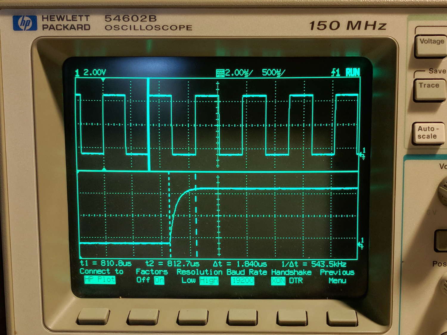
Although the scope command language offers a :PRINT? command, it produces output in HP PCL, from which there seems no practical way to get a raster image format like PNG. So this remains an output-only transfer triggered by poking the PRINT SCREEN softkey, after first setting the serial parameters:
HP 54602 scope serial parameters
In text:
Connect to: HP Plotter
Factors: ON
Resolution: HIGH
Baud rate: 19200 b/s
Handshake: XON
I have no idea what’s inside the serial cable at this late date (see the HP 8591 post for more musings), but the (paper!) manual says:
For three-wire operation, an XON/XOFF software handshake must be used to handle handshaking between the devices.
For extended hardwire operation, handshaking may be handled either with XON/XOFF or by manipulating the CTS and RTS lines of the oscilloscope.
For both three-wire and extended hardwire operation, the DCD and DSR inputs to the oscilloscope must remain high for proper operation.
With extended hardwire operation, a high on the CTS input allows the oscilloscope to send data and a low on this line disables the oscilloscope data transmission.
Likewise, a high on the RTS line allows the controller to send data and a low on this line signals a request for the controller to disable data transmission.
Since three-wire operation has no control over the CTS input, internal pull-up resistors in the oscilloscope ensure that this line remains high for proper three-wire operation.
Apparently, the DCD, DSR, and CTS inputs have internal pullups.
Hardware handshakings uses these signals:
Pin 4 RTS (Request To Send) is an output from the oscilloscope which can be used to control incoming data flow.
Pin 5 CTS (Clear To Send) is an input to the oscilloscope which controls data flow from the oscilloscope.
Pin 6 DSR (Data Set Ready) is an input to the oscilloscope which controls data flow from the oscilloscope within two bytes.
Pin 8 DCD (Data Carrier Detect) is an input to the oscilloscope which controls data flow from the oscilloscope within two bytes.
Pin 20 DTR (Data Terminal Ready) is an output from the oscilloscope which is enabled as long as the oscilloscope is turned on.
The scope wiggles them thusly:
The TD (Transmit Data) line from the oscilloscope must connect to the RD (Receive Data) line on the controller. Likewise, the RD line from the oscilloscope must connect to the TD line on the controller.
The RTS (Request To Send) line is an output from the oscilloscope which can be used to control incoming data flow. A high on the RTS line allows the controller to send data, and a low on this line signals a request for the controller to disable data transmission.
The CTS (Clear To Send), DSR (Data Set Ready), and DCD (Data Carrier Detect) lines are inputs to the oscilloscope which control data flow from the oscilloscope (Pin 2). Internal pull-up resistors in the oscilloscope assure the DCD and DSR lines remain high when they are not connected.
If DCD or DSR are connected to the controller, the controller must keep these lines and the CTS line high to enable the oscilloscope to send data to the controller. A low on any one of these lines will disable the oscilloscope data transmission.
Dropping the CTS line low during data transmission will stop oscilloscope data transmission immediately.
Dropping either the DSR or DCD line low during data transmission will stop oscilloscope data transmission, but as many as two additional bytes may be transmitted from the oscilloscope.
The “as many as two additional bytes may be transmitted” suggests the same problem as with the HP 8591 spectrum analyzer at 19200 b/s, wherein it seems to overrun the PS410 input despite the flickering CTS control line.
I set up hardware handshaking in the PS410 and discovered the CTS line flickers as it does with the 8591, but the transfer complete without overruns. Perhaps the 8591 sends more than however many characters the PS410 can handle after calling for a pause?
The Kermit setup points to Serial Port 1 on the PS410:
set host 192.168.1.40 7001 /raw-socket
set modem none
This file contains hidden or bidirectional Unicode text that may be interpreted or compiled differently than what appears below. To review, open the file in an editor that reveals hidden Unicode characters.
Learn more about bidirectional Unicode characters
The objective is to capture screen shots from the HP 8591 spectrum analyzer, now connected to Serial Port 2 of the Sena PS410 serial server.
My analyzer is an old one with a 3322A serial number, so its Opt 023 came with a genuine DB-25 female connector, not the DE-9 male connector described in the HP doc for the later Op 043 hardware. With that in mind, the HP doc says the spectrum analyzer supports only hardware handshaking:
Baud rate 300 to 57,000 baud.
8 bits per character.
1 stop bit.
No parity.
Software handshake – none.
Xon/Xoff and ENQ/ACK not supported by the spectrum analyzer.
The manual enumerates the handshaking lines:
Request to send (RTS) – Output signal indicates that the spectrum analyzer is ready to communicate. This line is true at power-up and stays true while power is on.
Clear to send (CTS) – Input signal indicates that the external controller is ready to receive data.
Data terminal ready (DTR) – Output signal from the spectrum analyzer. When the input buffer is full, this line goes false.
Data set ready (DSR) – Is not available.
Data carrier detect (DCD) – Input to the spectrum analyzer. If DCD is true, the spectrum analyzer will receive data from the controller. If false, no data will be input. The data will be ignored.
Furthermore, it is written:
The spectrum analyzer checks its CTS input before transmitting data to the computer. If the CTS line is false, the spectrum analyzer will not transmit data. The spectrum analyzer transmits data when the CTS line is true.
The spectrum analyzer sets the DTR line (PC CTS) false when its input buffer is full.
They offer several wiring diagrams, none of which correspond to the hardware on my bench, but swapping the “Personal Computer” and “Analyzer” headings on this diagram seems close to reality:
HP 8591 – RS232 DB25 to DE9 wiring diagram
On the other end of the cable, the PS410 does “hardware flow control using RTS/CTS”. They also offer a diagram:
Sena PS410 – RS232 wiring diagram
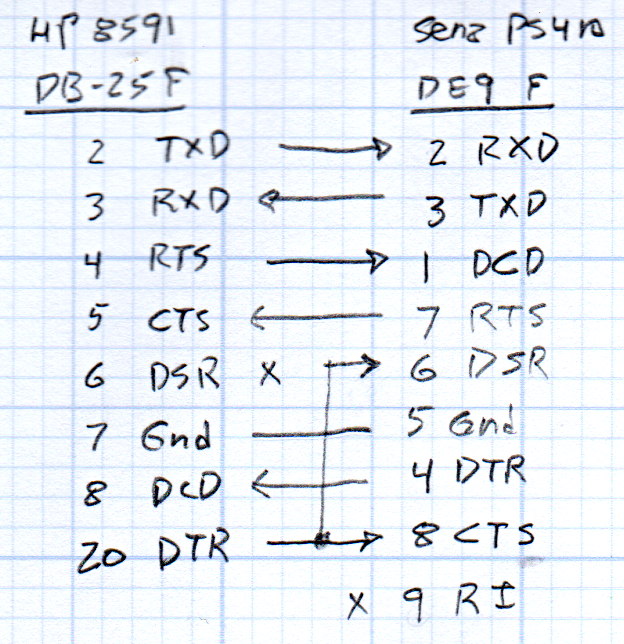
So I rewired the cable thusly:
HP 8591 vs Sena PS410 – RS232 cable diagram
Pin 1 on the 8591 interface connects to both frame ground and signal ground and, back when I first made this cable, many years ago, I had wired it to the shield of the cable and thence to the DE9 shell. Alas, the PS410 took offense; for reasons I don’t understand, a shell-to-ground connection ignites a ferrite bead on the PS410’s PCB.
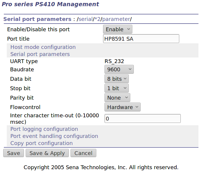
With the rewired cable in hand, the PS410 serial port setup looks like this:
Port 2 – 8591 serial config
The PS410 apparently wiggles its RTS output after every byte it receives, because the CTS input at the 8591 turns into a blur during screen captures. This seems unaffected by the Inter character time-out setting and doesn’t (seem to) produce any problems, so it’s like that and that’s the way it is.
Using 9600 b/s isn’t as slow as you might think. The HP manual notes:
Some of the programs in this manual use 1200 baud for proper operation. If your system uses the RS-232 handshake lines, you can use 9600 baud for all of the programs.
I tried 19200 b/s and got mysterious errors that resemble overruns, which suggests the 8591 ignores the PS410’s flickering RTS output. The screen dumps require only a few seconds, so it’s not a big deal, although timing issues have a way of resurfacing at the most inopportune, uh, times.
Kermit knows how to handle network sockets and suchlike, so aiming it at the spectrum analyzer is a one-liner:
set host 192.168.1.40 7002 /raw-socket
set modem none
The /raw-socket disables Kermit’s default Telnet interface, preventing it from squirting IAC + BRK characters when closing the session; I think that’s what happens, but I don’t use Telnet enough to know better. As you might expect, the 8591 deals poorly with characters outside its lexicon.
It’s not obvious set modem none does anything in this context, but it seems reasonable.
Then the rest of the script Just Works:
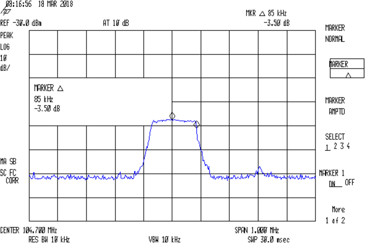
FM 104.7 MHz peak hold
Which is the peak-hold spectrum of a local FM station, as received through an amateur radio HT rubber duck antenna.
This file contains hidden or bidirectional Unicode text that may be interpreted or compiled differently than what appears below. To review, open the file in an editor that reveals hidden Unicode characters.
Learn more about bidirectional Unicode characters
Although I cannot explain why those ferrite beads lit up, it seems connecting the DE-9 shell to the serial device ground is an Extremely Bad Idea. I removed that wire from the HP 8591 spectrum analyzer cable and everything seems to work, so I’ll declare victory:
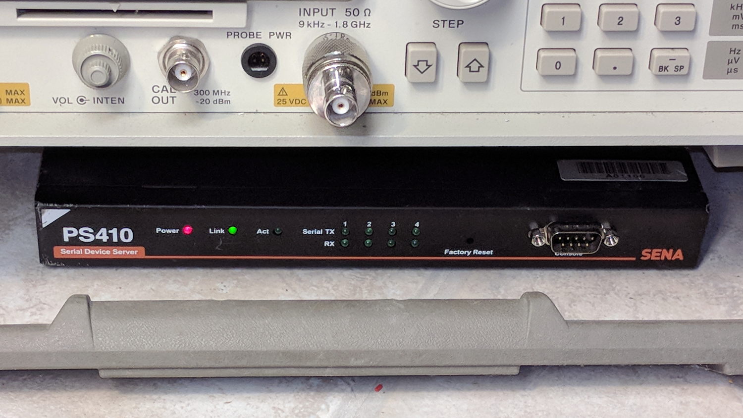
Sena PS410 Serial Server – in action
Not shown: the tangle of cables tucked behind that tidy box. You can plug a serial terminal into the DE-9 connector, but it’s much easier to use the PS410’s web interface.
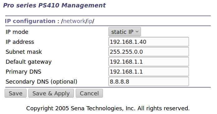
It needs a static IP address to make it findable, although I also told the router to force the same address should it start up in DHCP mode:
IP Configuration
Yeah, Google DNS, if all else fails.
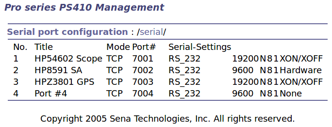
The serial port overview:
Serial port overview
I’ll go into more detail in a while about individual device setups and the scripts slurping screen shots out of them, but giving each one a useful name is a Good Idea, even though it doesn’t appear anywhere else. I changed the default Inactivity Timeout for each port from the default 100 seconds to zero, thereby preventing the PS410 from closing the connection due to inactivity:
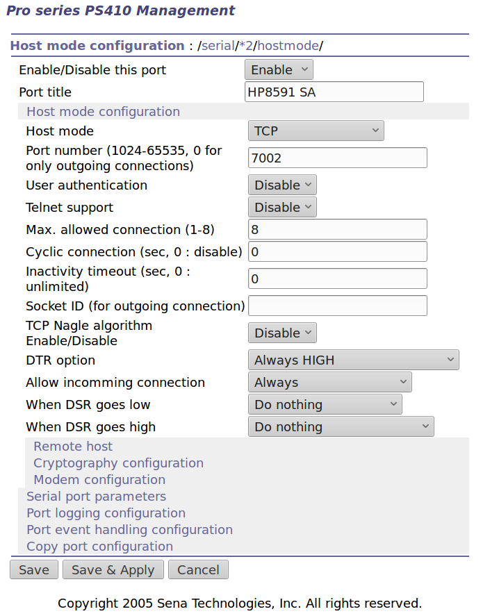
Serial Port 2 – host params
The DTR and DSR defaults work out well; the other choices solve problems I don’t have. Indeed, the PS410 has a myriad configuration options best left in their Disabled state.
The serial parameters for each port need tweaking to suit the hardware gadget on the other end of the cable:
Serial Port 2 – serial params
Flow Control applies between the PS410 and the gadget. You can choose:
Disabled
XON/XOFF – in-band characters
RTS/CTS – RS-232 hardware signals
Somewhat to my surprise, It Just Worked despite my blundering.
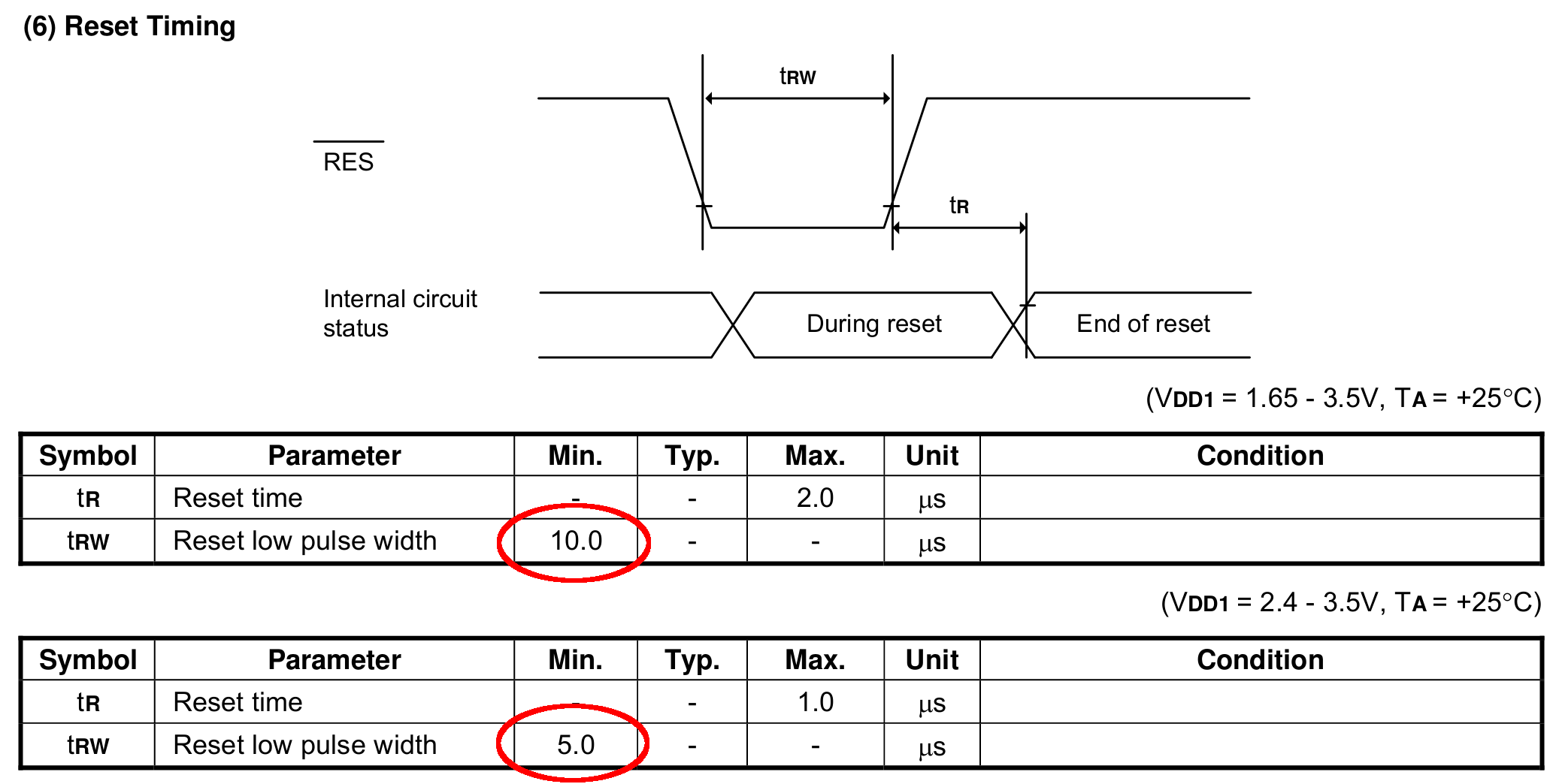
Slowing the SPI clock and updating the drivers having had no noticeable effect on the OLED display corruption, I once again pondered the SH1106 controller timing specs.
The chip reset seems remarkably slow, even at maximum VCC:
SH1106 – Reset Timing Specs
I think the relevant code is in the luma.core driver’s serial.py file. On the RPi, it resides in /usr/local/lib/python2.7/dist-packages/luma/core/interface/.
As far as I can tell, the bitbang class handles all the setup and teardown around the actual data transfers, but it’s not clear (to me, anyway) how it interacts with the underlying hardware SPI machinery.
So, let’s add some sleepiness to the Reset code:
        if self._RST is not None:
            self._gpio.output(self._RST, self._gpio.LOW)  # Reset device
            time.sleep(1.0e-3)
            self._gpio.output(self._RST, self._gpio.HIGH)  # Keep RESET pulled high
            time.sleep(1.0e-3)
A few milliseconds, rather than a few (hundred) microseconds, won’t make any perceptible difference.
Similarly, the Chip Select and Address (Command/Data) signals require more delay than might occur between successive Python statements:
SH1106 – SPI Address and Select Timing Specs
This should do the trick, again with excessive delay:
        if self._DC:
            self._gpio.output(self._DC, self._cmd_mode)
            time.sleep(1.0e-3)

... snippage ...

        if self._DC:
            self._gpio.output(self._DC, self._data_mode)
            time.sleep(1.0e-3)

... snippage ...

        if self._CE:
            gpio.output(self._CE, gpio.LOW)  # Active low
            time.sleep(1.0e-3)

... snippage ...

        if self._CE:
            gpio.output(self._CE, gpio.HIGH)
            time.sleep(1.0e-3)
Although it shouldn’t be necessary, I blew away the pyc files to prevent future confusion over who’s doing what with which.
Once again, this will require several weeks to see whether the situation changes for the better.