Ed Nisley's Blog: Shop notes, electronics, firmware, machinery, 3D printing, laser cuttery, and curiosities. Contents: 100% human thinking, 0% AI slop.
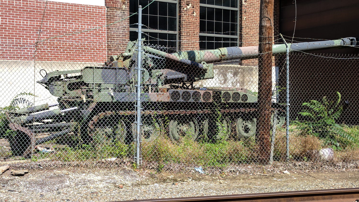
Back in the day, being 30 km away from a kiloton or ten of nuclear blast was deemed Far Enough, although nobody actually pulled the string to find out. Apparently, sections of surplus barrels make hella-good bunker buster bombs, at least when you’re in a hurry.
Obsolete, of course, explaining why it’s parked behind the York Agricultural and Industrial Museum, seen from the wonderfulHeritage Rail Trail. We rode south from York almost to the the Maryland line, then back again; a good time was had by all.
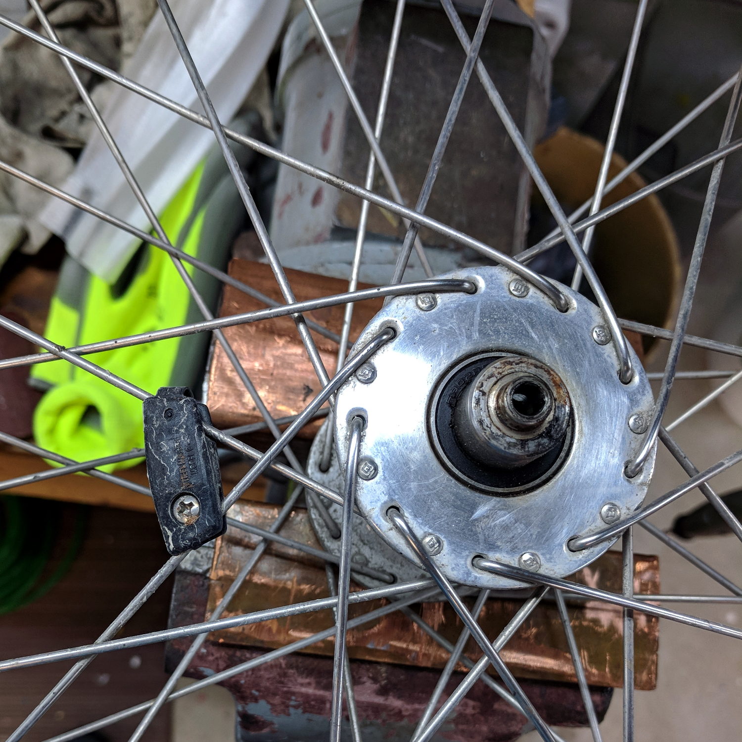
For future reference, the rebuilt wheel spoke tensions came out around 25, slightly lower than the 27-ish I measured on Mary’s bike; it didn’t occur to me to measure the tension until after I’d relaxed the spokes. I’ll ride it for a while before doing any tweakage.
The spoke pattern is pretty close to four-cross, due to the large-flange Phil Wood hubs:
Tour Easy Front Spoke Pattern
Which makes for a hella-strong wheel, particularly seeing as how it’s very lightly loaded. The Tour Easy we got for our lass came with a radially spoked rim around a Phil hub.
I transferred the hub and laced spokes intact to the new rim by the simple expedient of duct-taping the spokes into platters, removing the nipples, stacking the rims, sliding the spokes across into their new homes, reinstalling the nipples, then tightening as usual.
The top surface of the Anker LC40 flashlight serving as the daytime running light on Mary’s bike sees plenty of sunlight, particularly when it’s sitting beside her garden plots, and the black anodized finish on the screw-in battery cap has begun fading:
Anker LC40 Flashlight – Anodizing fade
The bottom side of the cap is in fine shape, as is the main case, so the two parts came from different metal finishing lines.
The light on my bike, a marginally newer and essentially identical Bolder LC40, remains all black. I have no idea what “Bolder” means in this context.
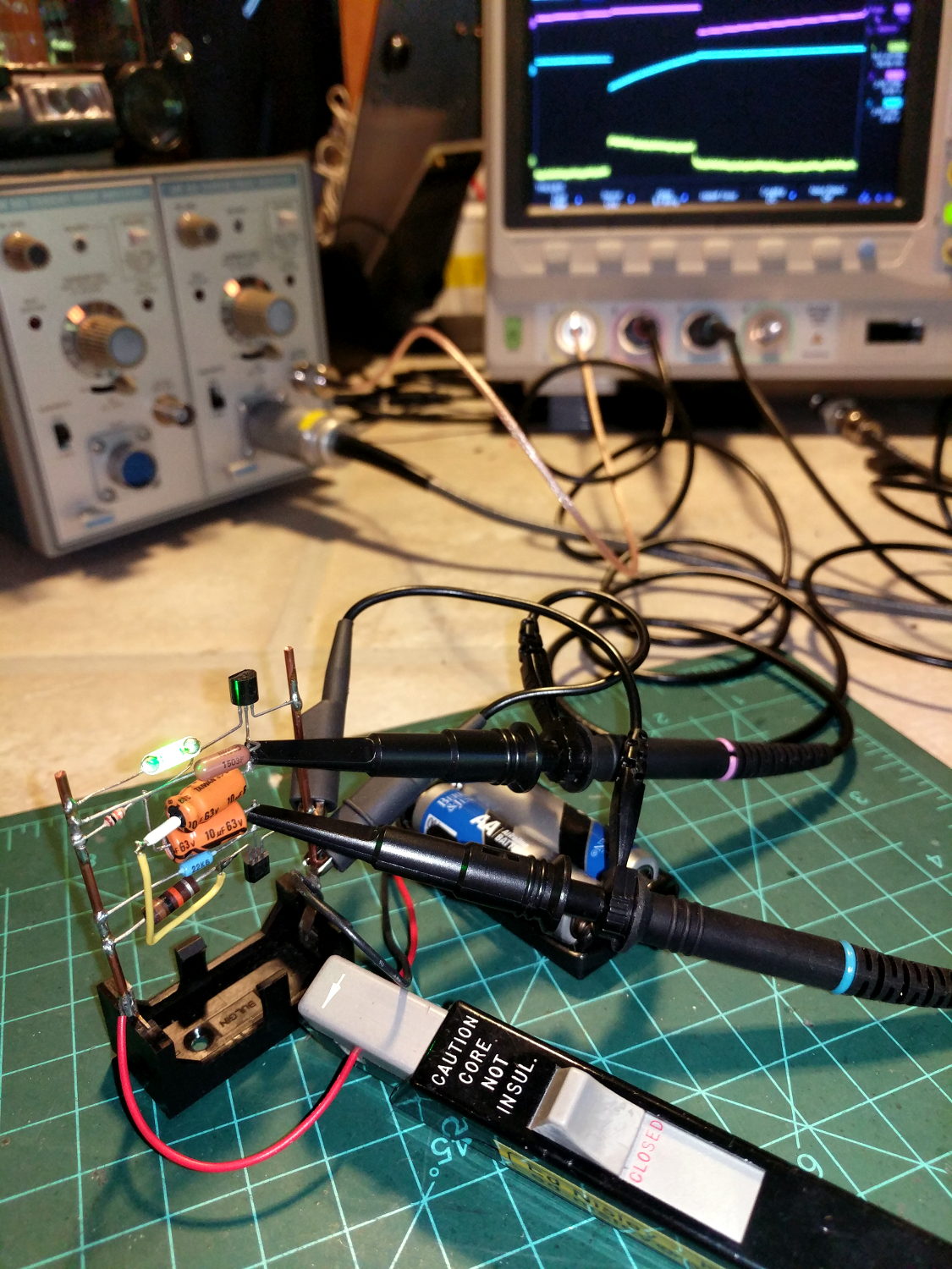
The question occasionally comes up as to why one would want a Tektronix A6302 Hall effect current probe and AM503 amplifier. The answer is simple: non-contact, essentially non-invasive current monitoring.
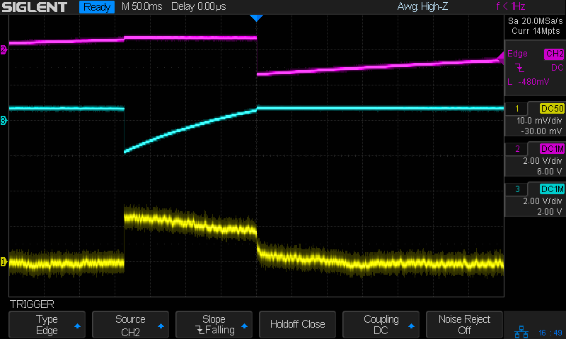
The scope screen in the background shows the two base voltages at the top, plus the overall battery current along the bottom:
Tek A6302 – Astable multivibrator – LED current 1 mA-div
The current at 1 mA/div shows plenty of noise, but the 200 ms LED pulse is barely 1 mA tall. The two AA alkaline cells have faded to 2.5 V, so the “wearable” white-LED-with-dyed-overcoat runs far under its nominal 3.6-ish V spec.
There’s basically no other way to get that result, because inserting a current-sense resistor into the circuit will alter the results, plus be intractably difficult to measure, particularly if you need the current in a non-ground-referenced branch of the circuit.
The AM503 has terrible thermal drift, by contemporary standards, but after the first half-hour or so it’s manageable for short durations. I’m thinking of epoxying a small knob to the screwdriver-adjustable twiddlepot to simplify the baseline adjustment.
Alas, even non-working probes and amps have become eBay collectables. You could, of course, buy new.
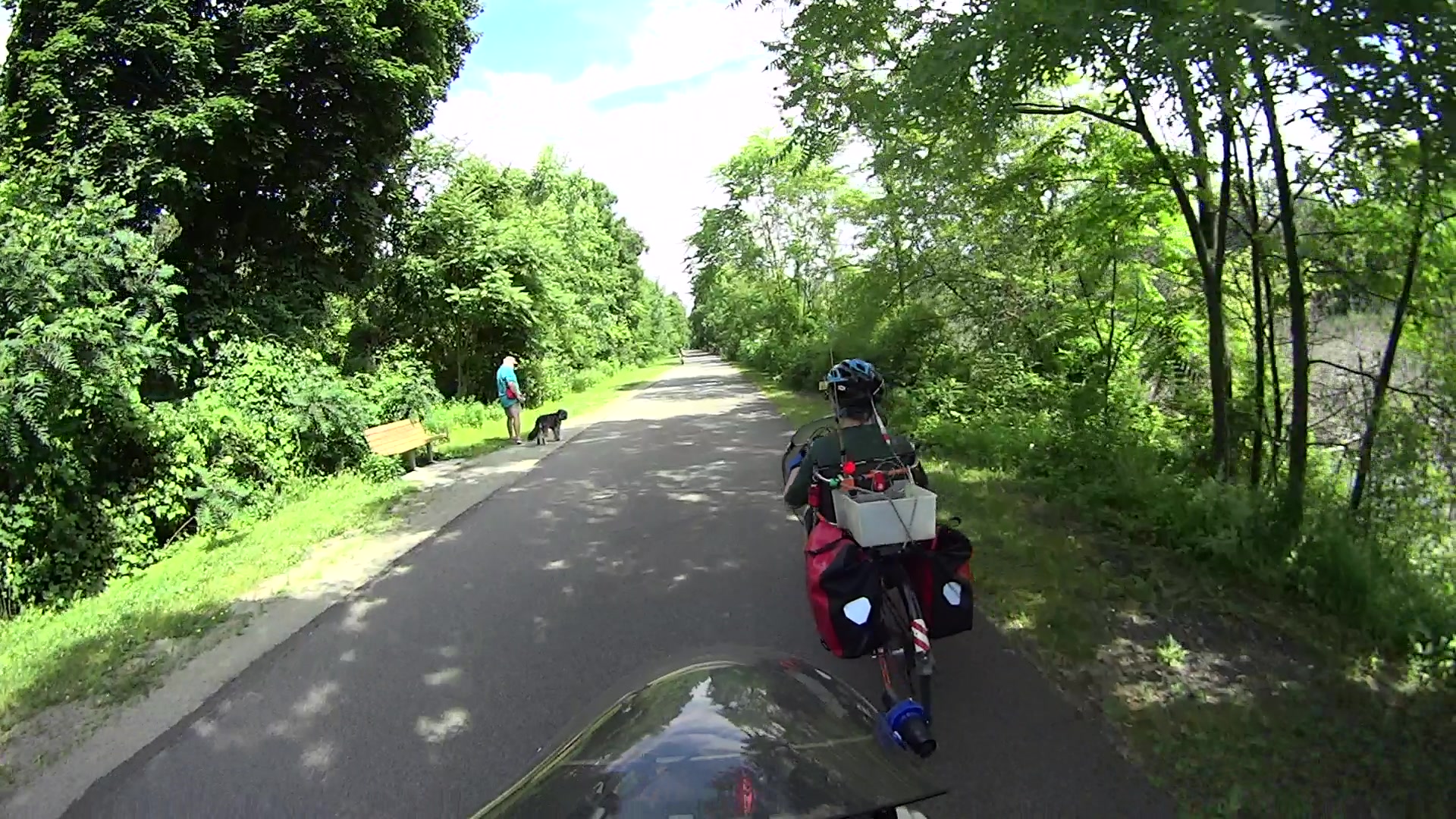
Although the pair of Ortlieb Back-Roller packs on Mary’s bike make her look like a long-distance tourist, we’re actually on our way to her garden plot:
AS30V-0285
The left-side pack suddenly seemed unusually floppy:
AS30V-0300
One second later:
AS30V-0360
Another second and it’s visible under my right hand:
AS30V-0420
The view from her bike at about the same time:
Ortlieb-0158
I’m expecting to fall to my right, but it’d have been better if I hadn’t kicked the bag:
Ortlieb-0169
The pack went under the rear wheel and out the far side:
Ortlieb-0185
Where it came to rest in the middle of the trail:
Ortlib pack drop – aftermath
Elapsed time from the first picture: just under 5 s.
Did you notice the other cyclist in the other pictures? She’s why I veered so hard to my right!
A pair of these latches hold the pack onto the rear rack:
Ortlieb pack drop – QL latch detail
When they’re properly engaged, they look like this:
Ortlieb pack drop – QL latch – secure
When they’re not, they look like this:
Ortlieb pack drop – QL latch – whoopsie
Which is obvious in the picture and inconspicuous in real life.
The strap emerging from the top of the latch serves as both a carrying handle and latch release: pull upward to open the latches and release them from the bar, lift to remove the pack, and carry it away as you go. Installing the pack proceeds in reverse: lower the pack onto the rack bar, release the handle, and the latches engage.
Unless the pack is empty enough to not quite fully open the latches as you carry it, in which case the closed latches simply rest on the bar. We’ve both made that mistake and I generally give her packs a quick glance to ensure sure they’re latched. In this case, the plastic drawer atop the racks (carrying seedling pots on their way to the garden) completely concealed the pack latches.
Tree roots have been creasing the asphalt along that section of the rail trail: the bike finally bounced hard enough to lift the drawer and fall off the rack rod.
Memo to Self: In addition to the visual check, lift the packs using the strap across the middle holding the rolled-down top in place. Remember, don’t check by lifting the carrying handle, because it just releases the latches; another easy mistake to make.