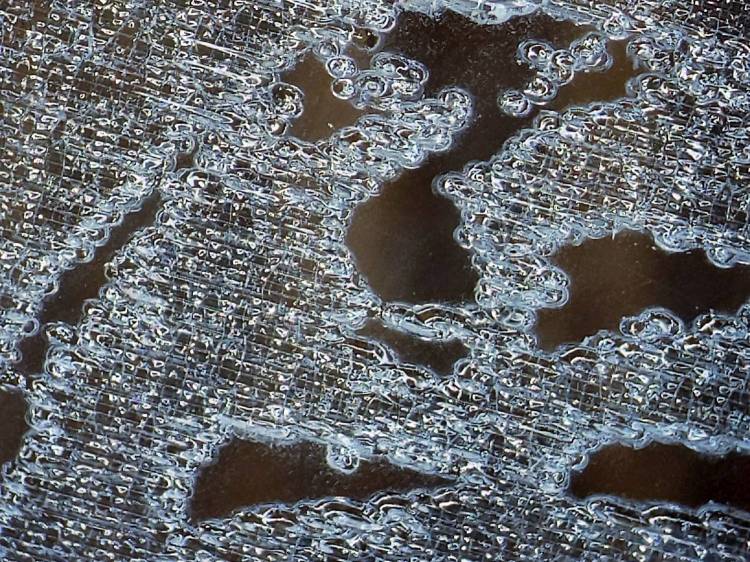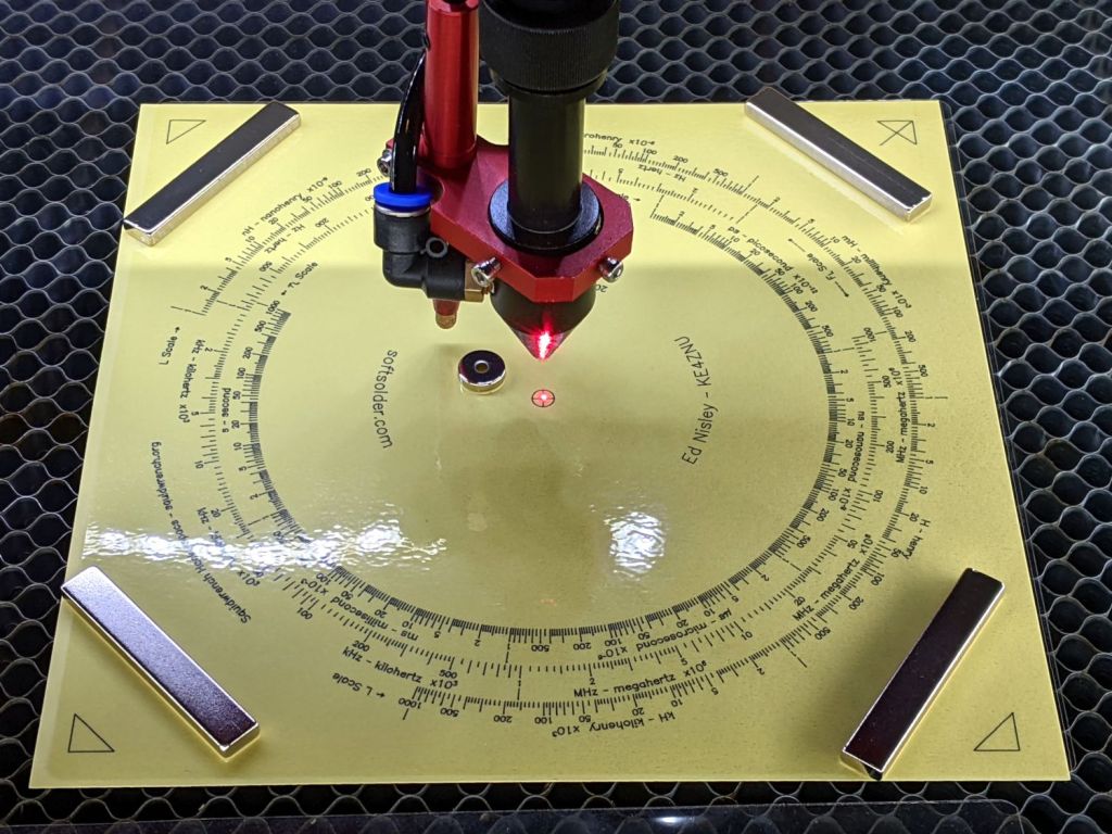
The setup for cutting the Tektronix Circuit Computer decks looks like this:

Four neodymium bar magnets hold the corners flat against the honeycomb and the neo disk magnet pins the center down, thus ensuring the red alignment laser meets the cutting beam at its focal point on the surface.
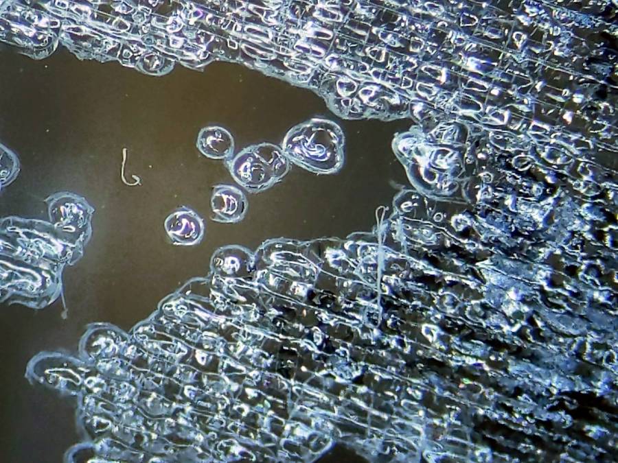
The triangular shapes mark the OD of the perimeter (177.8 mm) plus twice the cut margin on each side (2×2 mm), with the tick mark in the upper right ensuring I slap every deck down in the proper orientation. Aligning the two right marks to the edge of the honeycomb frame (with a straightedge for some offset) aims the deck’s 0° index along the cutter’s X axis.
The cut pattern origin is, naturally enough, the center point of the deck, so aligning the red dot to the center cross should put the OD cut at the place all around the perimeter. For confirmation, I fire the laser (“A single ping, Comrade.”) and verify the hole is in the middle of the cross.
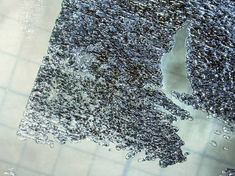
Before cutting the deck, the laser also marks the corner shapes, so this may come as some surprise:

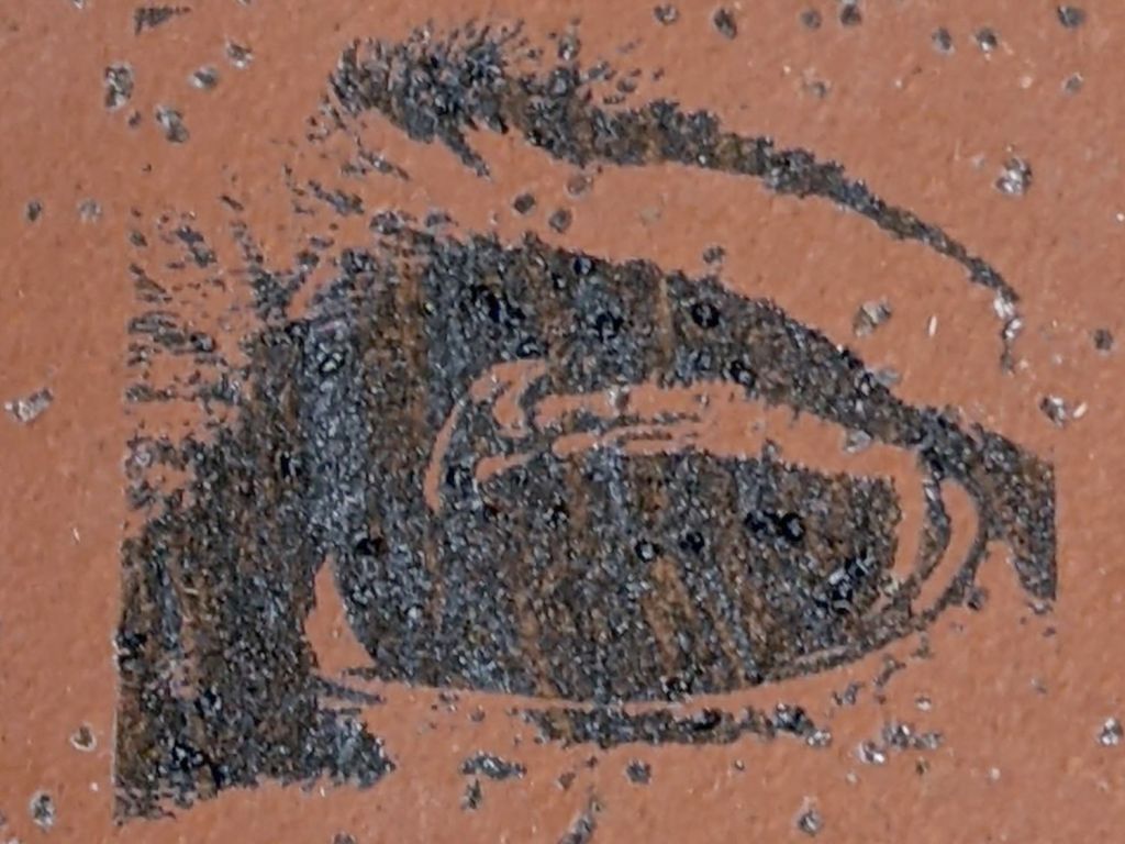
The laser printer (a venerable HP LaserJet 1200) produced the dark triangles and the laser cutter (a new OMTech 60 W) burned the light brown marks. The picture is a composite of the four corners, with the blank center removed to concentrate on what’s important.
The scrawls give the edge-to-edge distances in both inches (because that was the scale at hand) and converted to millimeters (because that’s how it’s laid out), with the L suffix for the laser marks.
What’s of interest is that you can’t overlay the two sets of marks by a combination of scaling and rotation with the centers (not shown) of the two patterns pinned together.
The laser measurements differ from the ideal 181.8 mm by 0.1 mm vertically and 0.4 mm horizontally. This may require dinking with the scale factors in the firmware, which I recall having weird values.
The LaserJet is definitely not a precise instrument, off by 0.4 mm vertically and a millimeter horizontally, with considerable variation. I think this comes down to unrealistic expectations for toner stuck to a flexible sheet wrapped around rollers and heated enough to melt dust into the fibers.
More study is indicated …