Laser cutter controllers generally set the tube current (and, thus, beam power) through a digital PWM signal to the HV power supply. Confusingly, the same power supply input terminal can receive an analog signal controlling the output current. Both signals have the same 0 to 5 V range.
I have yet to see a PWM frequency spec for any HV laser power supply, although surely there must be one. The specs for the Cloudray power supply on my shelf seem typical:
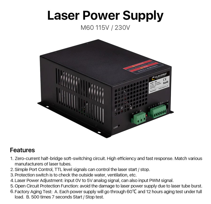
I have no spec sheet for the replacement power supply OMTech sent, which is now installed in the laser and is measured below. I believe all similar HV laser power supplies, regardless of the nominal brand, are essentially the same inside and will have similar, if not identical, behavior.
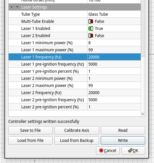
Controllers descending from the GRBL codebase default to a PWM frequency of 1 kHz, a legacy of using the PWM output for spindle motor speed control. GRBL’s Smoothieware descendant has a configuration option for the period in microsecond steps with (I think) a default of 20 µs = 50 kHz. Ruida controllers similar to the (Ryxon) KT332N in my OMTech laser (seem to) default to 20 kHz frequency:
The laser frequency is used to set the pulse frequency of the control signal used by the laser. The glass tube is generally set to about 20KHZ
KT332N Manual, p 55
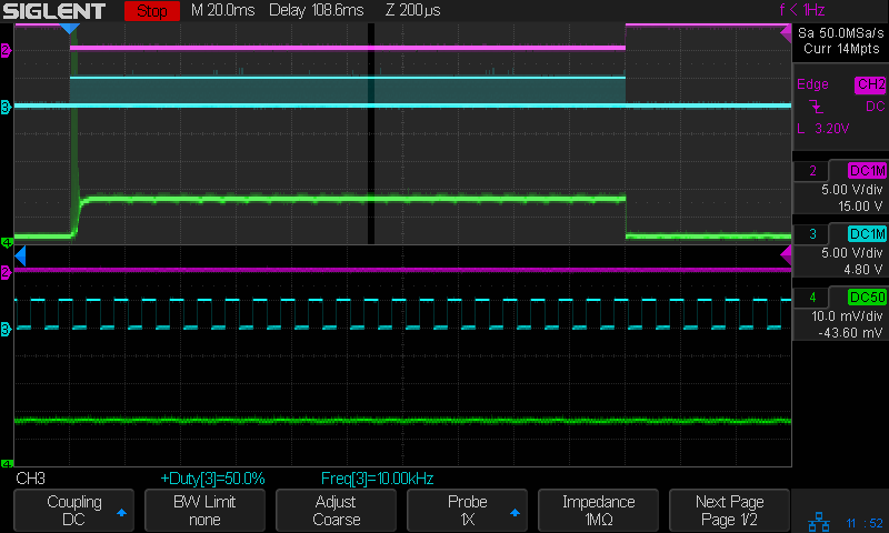
Knowing how a dozen measurements outweigh a thousand opinions, I recorded the power supply output current as a function of PWM frequency. The test setup is the same as for the original series of current measurements, with oscilloscope traces arranged thusly:
- 1 unused (yellow)
- 2 L-ON laser enable, low active (magenta)
- 3 PWM signal (cyan)
- 4 tube current – 10 mA/div (green)
I set the KT332N controller for a 200 ms pulse when poking the front-panel button, which is long enough to show any interesting behavior, and changed the PWM using its awkward controller interface. LightBurn provides access to the “vendor settings” which include the PWM frequency, which I set as needed:
So, we begin by varying the PWM frequency with a constant 50% PWM …
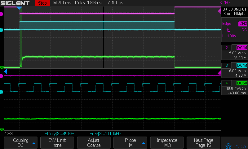
The default 20 kHz:

The upper half of the scope screen shows the entire 200 ms pulse, with the small slice near the middle appearing zoomed across the bottom half. The readout just above the buttons along the bottom gives the measured PWM percentage and frequency. The green trace shows the tube current is about 12 mA, half of the power supply’s maximum 25-ish mA.
The Tek current amplifier has plenty of thermal drift that I have not attempted to compensate, so always eyeball the average current with respect to the baseline around the pulse in the upper half of the screen.
No trace of the 20 kHz PWM signal appears in the tube current, which runs at a constant 12-ish mA for the duration of the 200 ms pulse.
Increasing the PWM frequency to 100 kHz (!) produces no change, although I cranked up the zoom timebase to better show the PWM pulses:
Reducing the PWM frequency to 10 kHz produces very small ripples in the output current corresponding to the PWM cycle:
At 5 kHz the tube current becomes sinusoidal, with an average around the same 12 mA produced at higher frequencies:

The sine wave current is about 90° out of phase with the square wave PWM, although much of that must come from delay through the entire power supply, rather than just an RC low-pass filter.
At 2 kHz the tube current takes on a decidedly lumpy look:

At 1 kHz there’s definitely something odd, perhaps a resonance, going on inside the supply, although the average current remains 12 mA:

At 500 Hz the PWM is slow enough that the tube current resembles the output of an integrator, rather than a filter:

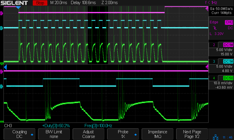
At 100 Hz, the digital PWM signal is so far below the filter cutoff that it’s behaving as an analog input, with the tube current ramping between minimum and maximum:

The current has regular full-on glitches halfway through the “off” part of the PWM signal, so running at absurdly low PWM frequencies does not prevent them. Also note that the PWM signal does not control the current at the same speed as the L-ON enable signal, due to the low-pass filter rolling off the transitions.
Now, holding the PWM frequency constant at (the absurdly low) 100 Hz and varying the % PWM duty cycle …
At 30% PWM, the output current becomes triangular due to the low-pass filter:

At 99% PWM, the output stays at the power supply’s 24 mA maximum output, with small downward ramps marking the 1% off times:

Some observations for this HV power supply, which seems typical of similar supplies sporting other “brand names”:
- A PWM frequency below 10 kHz introduces output current variations due to the power supply interpreting the PWM waveform as a somewhat analog input, rather than a purely digital signal. This effect increases as the frequency decreases.
- An Arduino-speed digital PWM near 1 kHz will be interpreted as an analog signal, with the tube current varying significantly around the PWM signal’s average analog value. It does not control the current in an on-off digital manner.
- Due to the effect of the low-pass filter, the PWM signal cannot switch the tube current between “full off” and “full on” at any frequency. The current will always follow a ramp with a slope controlled by the filter rolloff, so low PWM inputs will have low peak currents.
I must switch to the controller’s analog output …