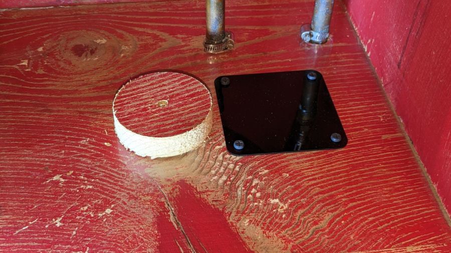
The MDF signs I made last year disintegrated pretty much on the expected schedule, so it’s time for something more durable:
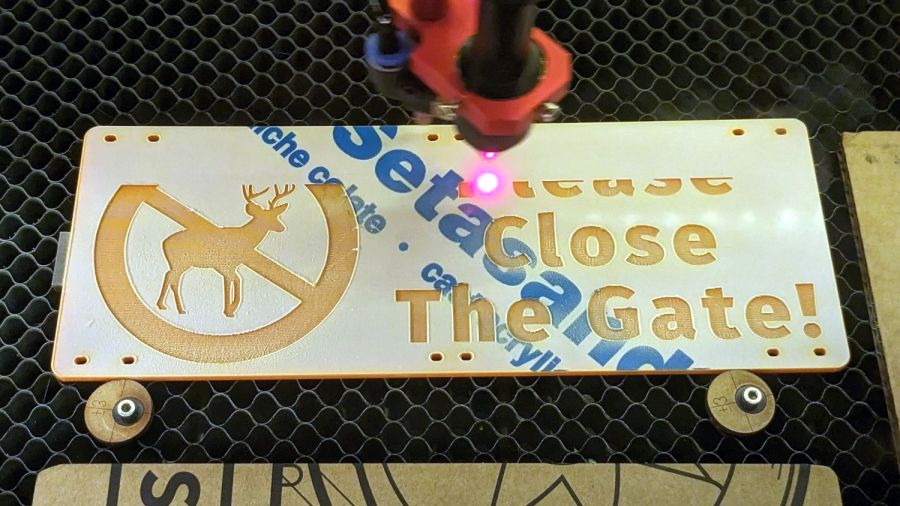
The idea is to engrave both sides of a 3 mm orange acrylic sheet, shoot it with rattlecan black paint, and declare victory. The second step awaits warmer weather, but at least I’m doing my part to prepare for the new gardening season.
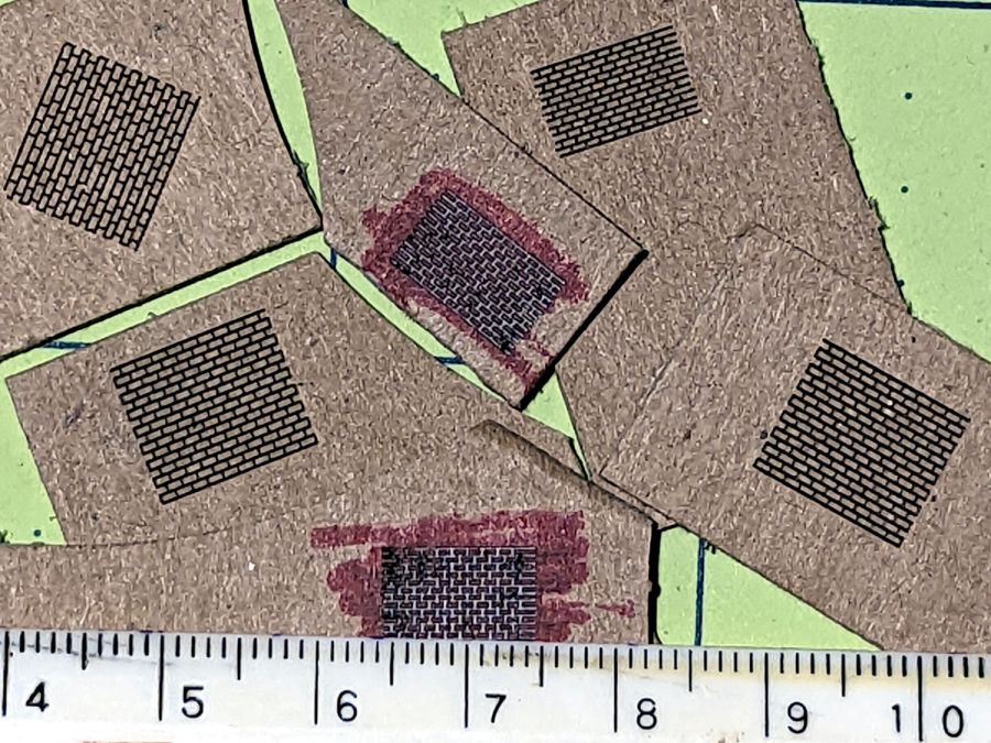
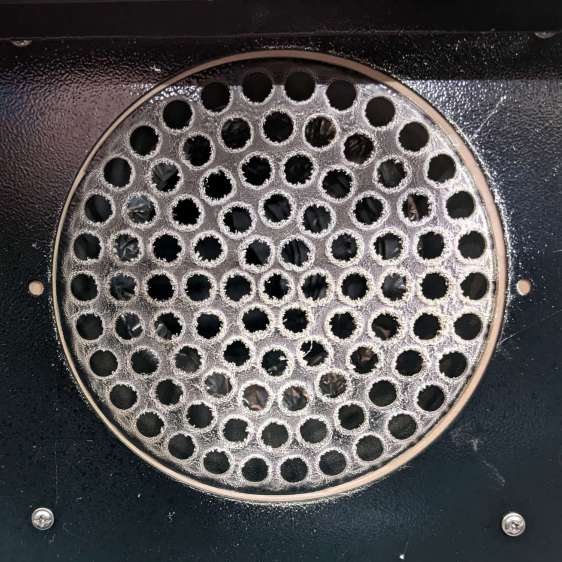
Vaporizing that much acrylic produces a fair bit of debris:

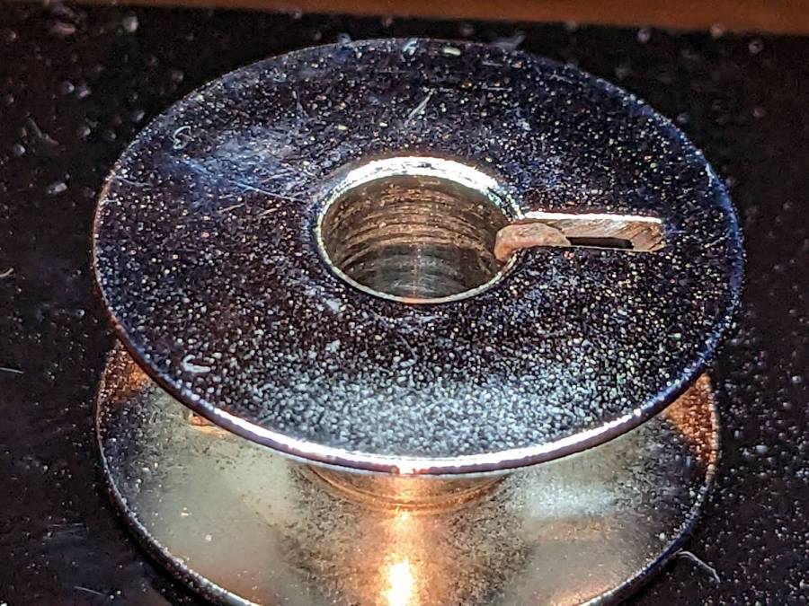
Some dust / vapor accumulates / condenses on the honeycomb platform beyond the orange sign, but most of it gets through to the baffle on the exhaust duct:
A closer look shows it really does grow out from the perimeter of each hole:
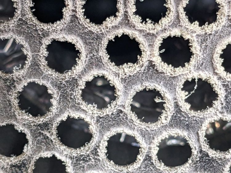
Now, if that doesn’t trip your trypophobia, nothing will …
A few passes with the trusty Electrolux vacuum’s dust brush brought the visible surfaces back to normal.
By now, the duct fan blades have surely layered on a good coating, too, which shall remain undisturbed until I find a better reason to open the duct.