
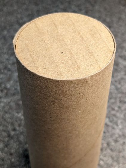
One of the Dripworks Micro-Flow valves in Mary’s garden started spraying water through the mold mark in the middle of the bottom:
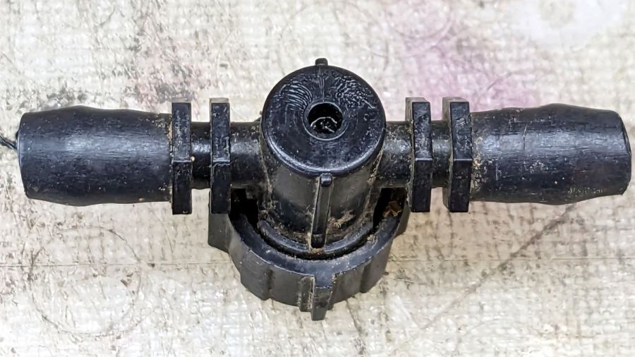
The autopsy produced a handful of pieces and inconclusive results: no visible holes or cracks.
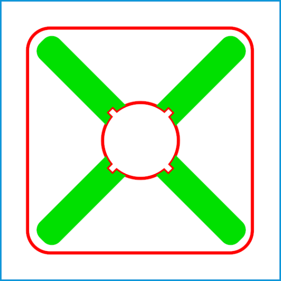
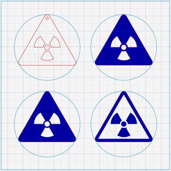
Having replaced it with a new (and drilled out) valve, I scanned the underside of the severed valve knob, blew out the contrast, imported it into LightBurn, and got a reasonable approximation to the outline:

A few more tweaks, weld the outline together, add some markers, and it’s ready for cutting:
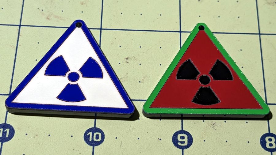
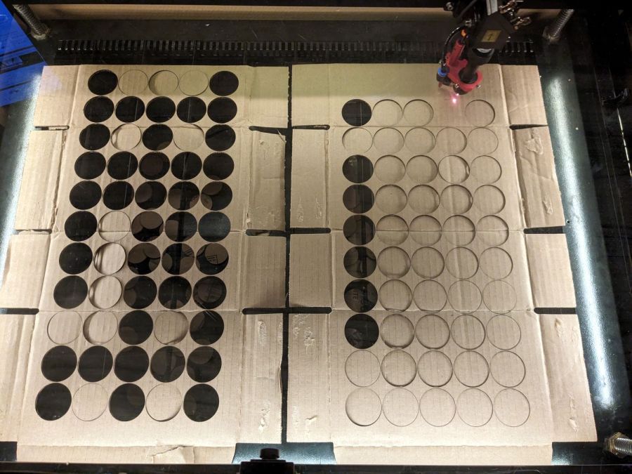
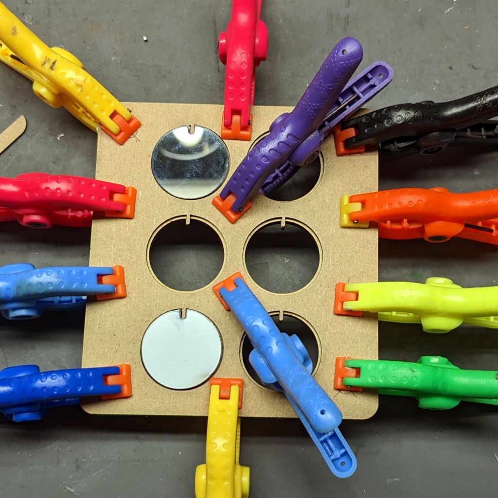
Having just done some earrings with PSA vinyl figures, I changed the (green) engraved layer to a kiss cut and Fired The Laser:
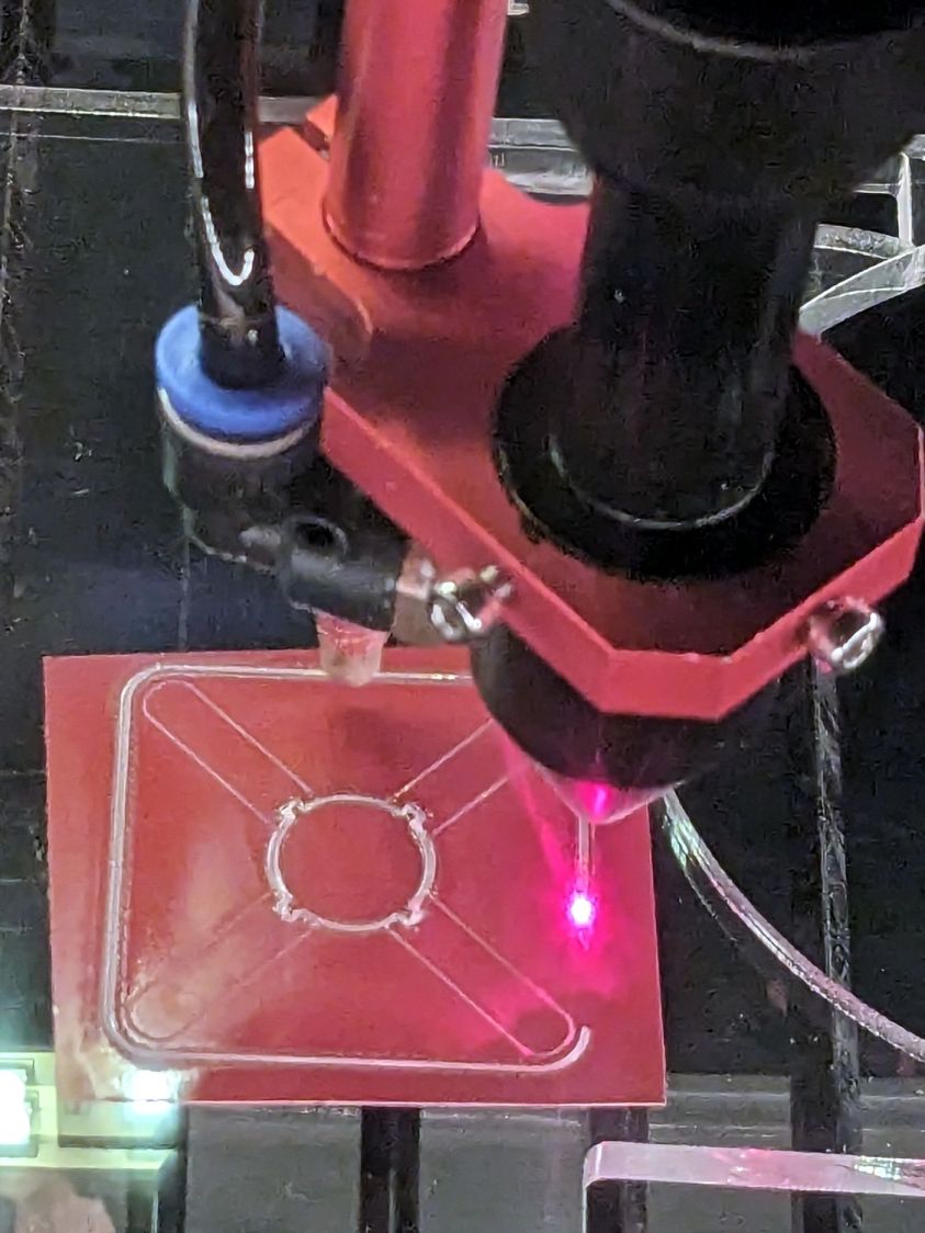
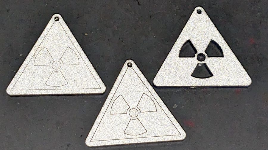
The mess in the vinyl around the through cuts in the ¼ inch acrylic sheet suggest engraving will work better. Lesson learned.
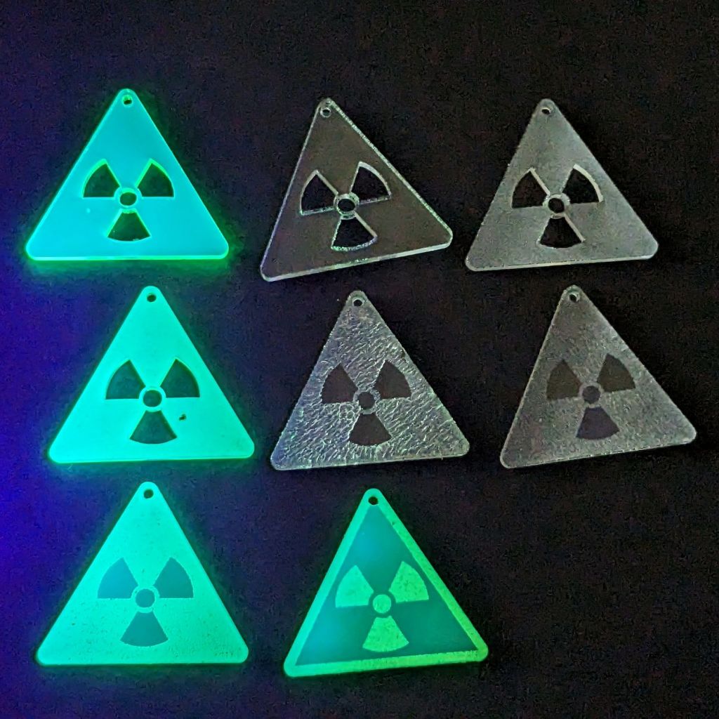
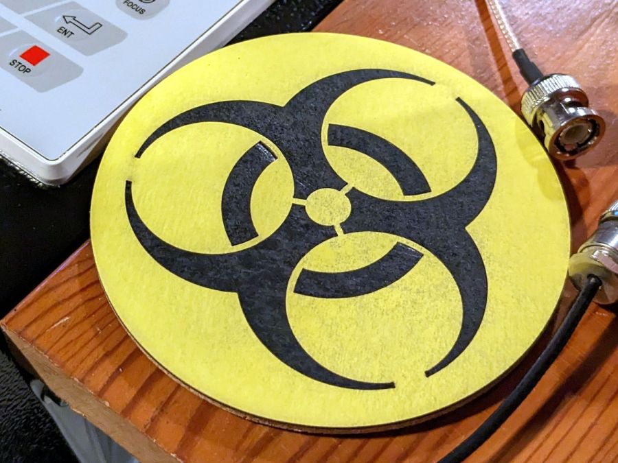
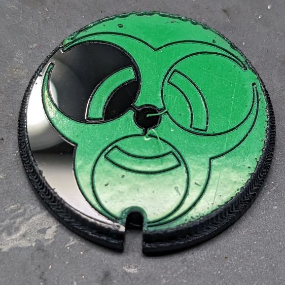
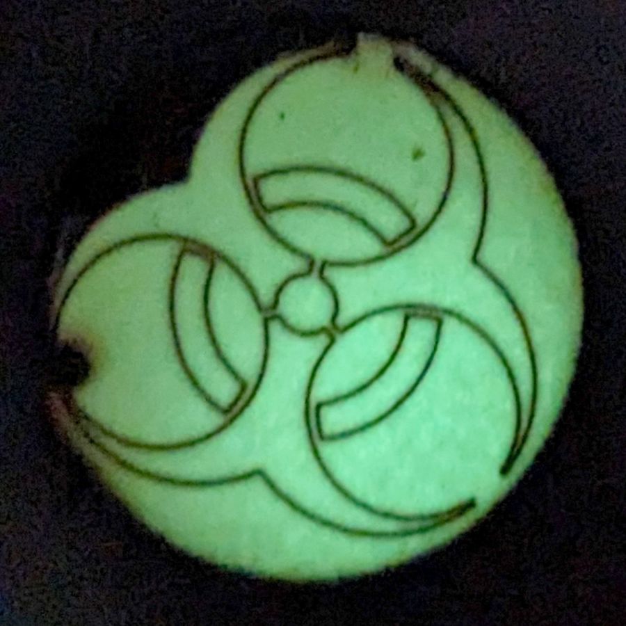
A few minutes of weeding produced a finger-friendly helper with scorches around the central ends of the vinyl:
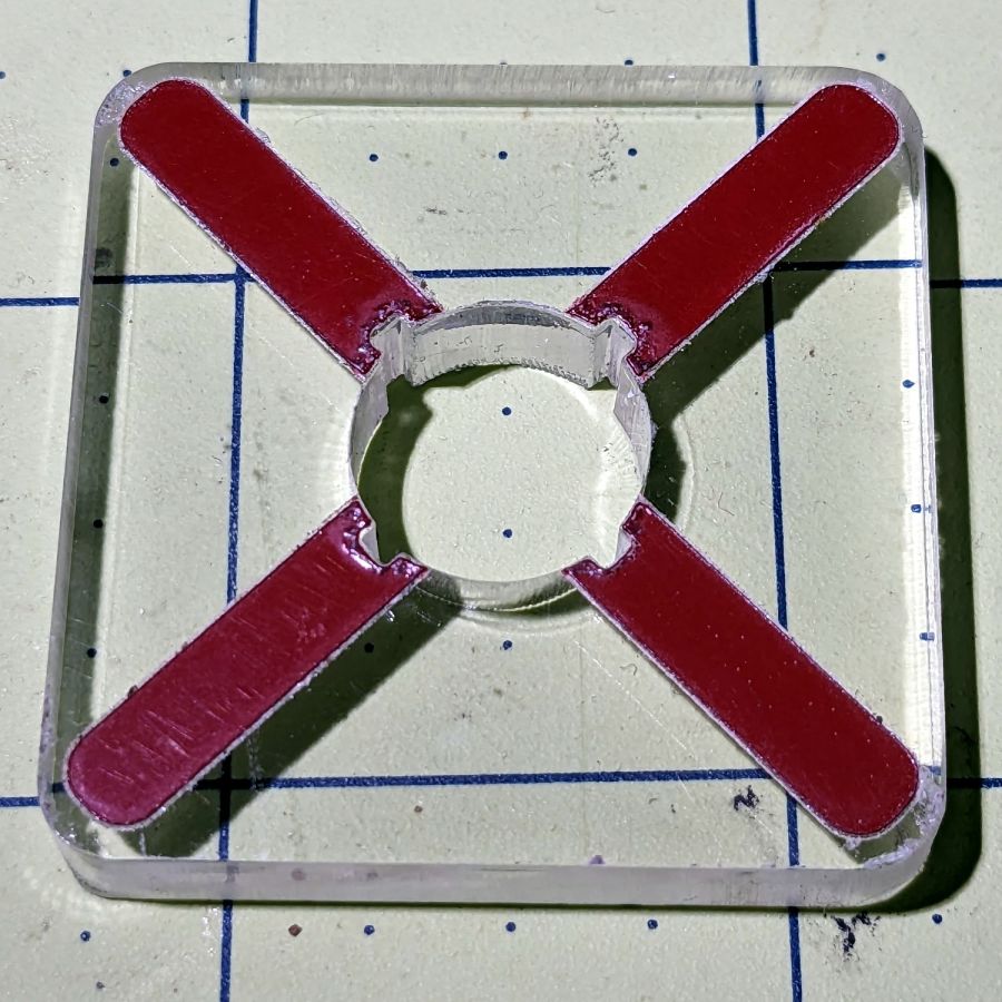
But it fits right over the knob, which was the whole point of the exercise:
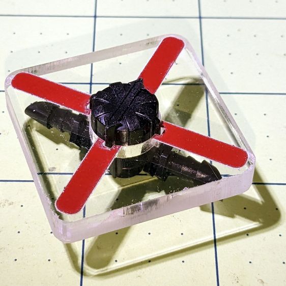
Now Mary can adjust the valve without squinting at obscure black-on-black shapes atop the knob.
I decided keying the helper to the knob so it fit in only one orientation on the knob would be a hindrance, because there’s no easy way to determine their mutual orientation without the aforementioned squinting. Now it’s a matter of putting the helper over the knob, turning it at most a quarter-turn until it drops around the knob, then making another quarter of a turn to put the other red marks parallel to the hose: if it was on, it’s now off, and vice versa.
After the PSA vinyl peels away, I’ll make another one with engraved lines and any other improvements.
The LightBurn SVG layout as a GitHub Gist:


