Ed Nisley's Blog: Shop notes, electronics, firmware, machinery, 3D printing, laser cuttery, and curiosities. Contents: 100% human thinking, 0% AI slop.
My pre-ride thumb check showed a flat rear tire on Mary’s Tour Easy:
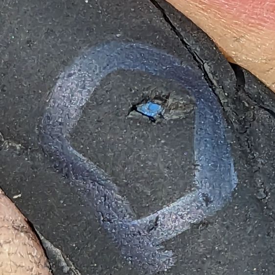
Glass chip – end view in tread
So we fetched groceries with the car.
As usual, no tire armor can withstand a glass blade:
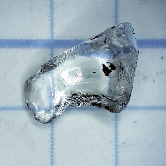
Glass Chip – side view
It’s a bit over 5 mm from the knife edge to the ground-flat end, just long enough to punch through a rather well-worn Schwalbe Marathon Plus tire and poke a slow leak in the tube.
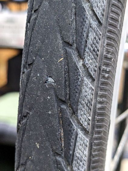
The tire has covered enough miles to wear the tread down to maybe half a millimeter over the blue armor layer:
Glass chip – tire damage
Time for a new tire!
For the record, the odometer is just shy of 35 k miles and she rides about 1500 miles a year; somewhat less over the last year for reasons not relevant here. As best I can tell, the tire has been on there for about five years and 7000 miles.
That’s made of rags from the box o’ wipes out of view on the right, laid out in no particular order, on a contrasting background to simplify the next step.
Tap the Trace button and fiddle with the sliders to get a nice solid outline, along with other junk off the edge of the cardboard:
Random fabric – LB trace
All of the traced vectors will be in a group:
Random fabric – LB shapes
Ungroup them, select the outline in the middle, invert the selection, and mass-delete the junk around the edges.
If you don’t move anything, the outline will be exactly over the shape on the platform. This will come in handy later.
Import all the shapes you want nested inside the outline, group them with the outline, and hand them to the Arrange → Nest Selected tool:
Random fabric – LB nesting setup
LightBurn saves the selected objects as an SVG file with the file name in the clipboard and fires up a browser tab at https://svgnest.com/. Upload the SVG and let the nesting algorithm chew away for a while:
Random fabric – LB nested
The weird triangles come from the Dot Mode perforations that ought not be there; inner shapes get subtracted from outer ones, which makes perfect sense. Your shapes will differ.
Download the nested shape SVG, load it back into LightBurn at the prompt generated after exporting the shapes, and LightBurn will apply the transforms to the original shapes. Put the outer shape on a tool layer and the inner shapes on whatever cutting layer you like, snap the outer shape (with the nested shapes inside) to the previously undisturbed outline of the stuff on the platform, and Fire The Laser!
Now there’s a pretty good chance I can do that again …
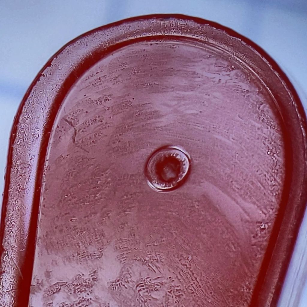
That’s the 0.3 mm exit wound in 3 mm acrylic, one of the mini-lathe chuck stops, carefully hand-held to align the channel.
Squinting at similar holes through clear acrylic shows they’re smoothly melted (as you’d expect), but not exactly perpendicular to the surface. I’m sure the acrylic gas pushes the beam around and erodes the sides of the channel as it boils out of the progressively deepening hole.
The entry wound is about half a millimeter:
Laser-cut pinhole – entry
The heat-distorted strip around the perimeter is less obvious in real life without magnification. The protective plastic film over the surface melts easily and, although it does keep the fumes from condensing, causes a bit of damage.
Each pinhole comes from a single dot in LightBurn’s Dot Mode, so you must arrange the dot spacing to match the path:
Lathe Chuck Stop – Pinhole distance
The pockets are on a 40 mm BCD, so they’re out 20 mm from the center and the hole-to-hole distance is:
34.64 mm = 2 × 20 mm × cos(30°)
Set the dot distance to that exact number and It Just Works.
The laser turns on for a specific number of milliseconds at each dot. In this case, I used 50 ms with the layer set to 70% PWM. You could surely optimize the values.
The starting pinhole gets drilled twice, which happens because Dot Mode expects to make a line of perforations with one dot at each end. In this case, the end of the last line overlaps the start of the first line; two lines would work better than a triangle.
You could make a square array from a single line with (many) dots at the desired spacing, separating the lines by the same spacing.
A circular array might work, too, with a straight line joining successive holes.
Undo would definitely be my copilot while figuring those out.
This could make an easily clogged trash strainer or a filter for small chunks.
CO₂ laser power meters seem to depend on a flat-black absorbing surface to soak up a (typically unfocused) beam pulse, backed by a known metal mass with a thermocouple to measure the temperature rise above ambient. Knowing the pulse width, the temperature rise, the absorber mass and specific heat capacity, you can compute the pulse energy and average power during the pulse.
Previous tinkering with an old Gentec ED-200 showed this works well, although the absorber surface took something of a beating because it was definitely not rated for the OMTech’s 60 W (claimed) beam power.
Rather than using a spendy absorber surface with a durable coating, perhaps a geometric absorber using reflective surfaces arranged to channel the energy into the material, rather than away from it, might suffice.
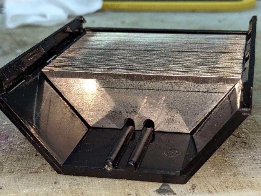
Consider a pack of ordinary utility knife blades:
Beam absorber – utility blades – overview
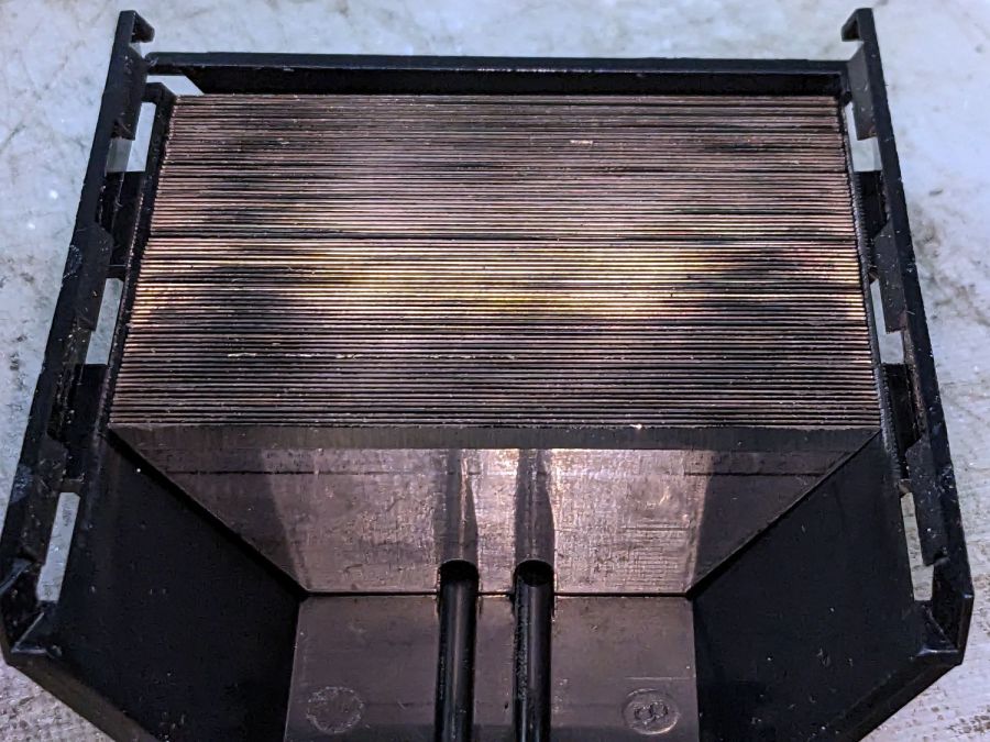
Seen kinda-sorta perpendicular to the sharpened side of the blade edge, they’re wonderfully reflective:
Beam absorber – utility blades – edge flat
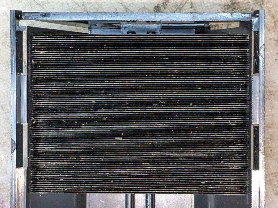
Seen perpendicular to the edge itself, they’re dead black:
Beam absorber – utility blades – edge-on
Well, pretty close to dead black. It’s darker in real life, with glimmers along the edge and the rest of it a deep black. The edges are sharp, but utility knife blades will lead a rough life and they don’t start out Scary Sharp.
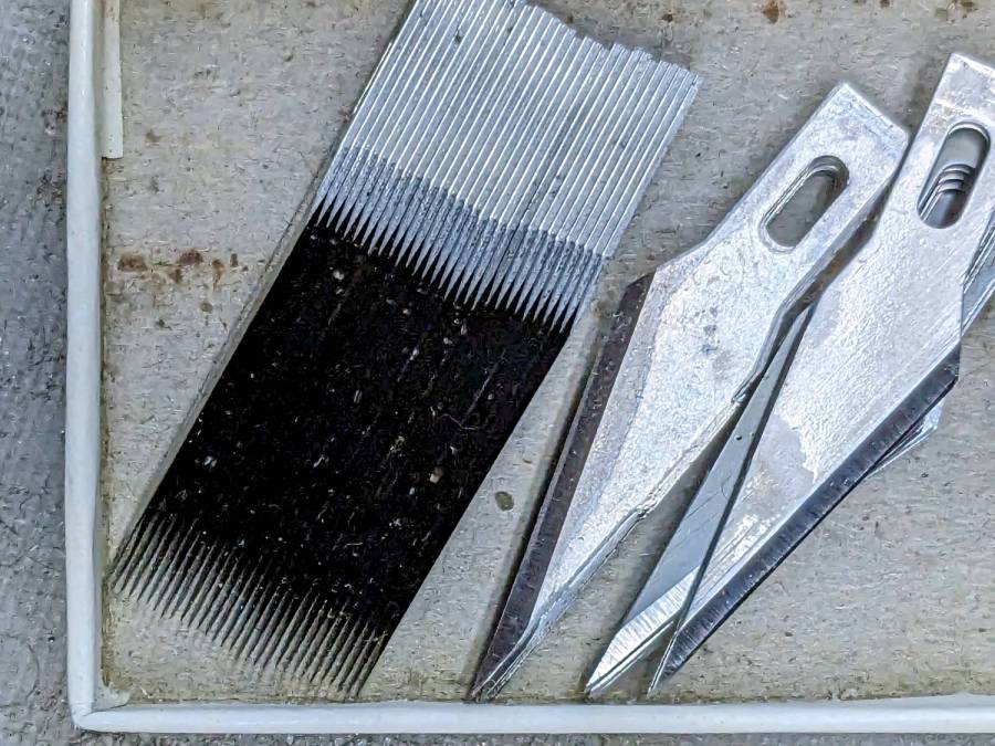
Xacto blades come closer to an ideal razor edge:
Beam absorber – Xacto 11 blades – edge-on
The only things you (well, I) see is dust on the edges. The rest is dead black, because light hitting any shiny surface is reflected deeper into the notch between two blades and eventually absorbed.
Double-edge razor blades are sharper and would likely be even blacker, particularly cheap ones without fancy lubricating coatings.
Bonus: the wavelength of CO₂ laser IR light is 10-20× that of visible light, which makes the surfaces that much more reflective. The geometry still channels the reflections into the block and nothing comes out.
There are some fairly obvious reasons why nobody uses a stack of razor blades as a beam absorber in real life:
Lethally sharp cutting hazard
Impossible to clean without wrecking the edge
But for personal use, why not?
Some doodles:
Steel has a specific heat around 0.47 J/g·K and a stack of utility blades weighing 140 g is 23 mm across. Soaking up a 60 W beam will raise the temperature of the stack by:
0.91 K/s = 60 J/s / (0.47 J/g·K × 140 g)
Which seems reasonable: fire a 10 s burst, measure the temperature rise, and multiply by 0.91.
Similarly, a stack of Xacto #11 weighing 15 g is 11 mm across and the temperature will rise 8.5 °C/s. You’d use that for lower power beams.
You could clamp the blades into a larger heatsink, perhaps with a thermocouple / thermistor in a hole drilled into the block.
Calibrate the stack / heatsink with an embedded cartridge heater: voltage × current × pulse width gives the power dumped into the block, so measuring the temperature rise gives you the temperature-power relation.
This feels like a great Arduino project, although it’s nowhere near getting started.
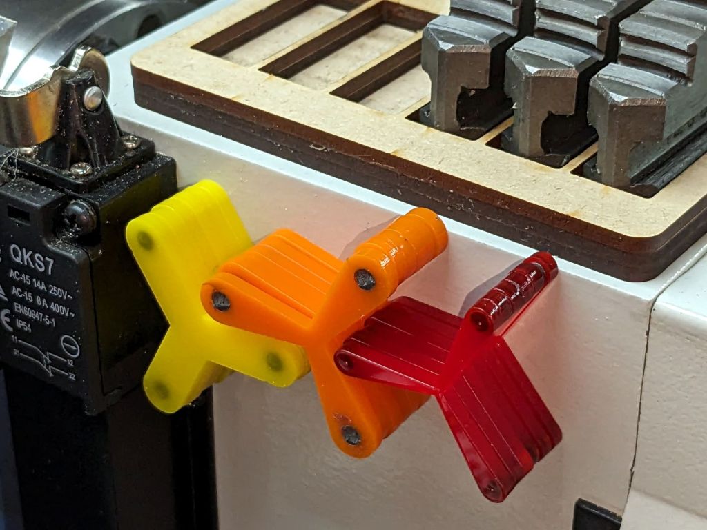
Daubing urethane adhesive into each pocket, sliding a tiny magnet atop the goo, and flipping them over onto a sheet of plastic atop the surface plate to let them cure went about the way you’d expect. Given the state of my fingertips, however, I was not about to fiddle with the phone / camera / anything, but it really did happen.
The final result:
Lathe Chuck Stops – on-lathe storage
The alert reader will notice the slight gap under the left leg of the first orange stop, which provides a good introduction for a few things that should happen differently the next time I do something like this.
To my credit, I got all but one of the 54=3×6×3 magnets into their pockets in the same orientation. That’s gotta count for something and, hey, that orange stop sticks to the chuck just fine.
That one also suffered from my failure to switch the Axis UI to metric units before touching off the Z axis at 0.1 mm, thereby putting the Z=0.0 level 2.53 mm below the surface. Fortunately, the 3 mm MDF baseplate prevented that error from creating three pockets in the tooling plate, although it did produce holes instead of pockets in the stop.
I dropped the magnets into the thru-cut stop on the surface plate and dabbed some adhesive atop the magnets to bond them into their holes. This worked fine and led me to suspect the easiest way to make these stops would be to just laser-cut the holes and skip the whole CNC thing.
The disadvantage of cutting the holes through is that adhesive will inevitably ooze out around the magnet and mess up the bottom surface of the stop. Sticking both the stop and the magnets onto kapton tape seems like it should seal well, but liquid always finds a way.
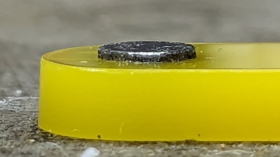
In any event, the two-part urethane adhesive (JB Plastic Bonder) expands slightly as it cures, which is great for gap filling and not so good for precision bonding. With the pockets in the other 17 stops arranged open-side down, the magnets held themselves firmly to the plastic sheet atop the surface plate and the expanding urethane pushed the acrylic stop upward, leaving the magnets standing slightly proud of the stop’s surface:
Lathe Chuck Stops – protruding magnet
Not by much, mind you, but not what I wanted, having painstakingly cut the pockets 2.2 mm deep for a 2.0 mm magnet.
Next time, dot some slow-cure clear pouring epoxy in each pocket, put the stop on the surface plate with the pocket facing up, then drop the magnet in place. The magnet pulls itself into the pocket, the epoxy doesn’t expand, any overflow will fill in over the magnet, and anything sticking out can be sanded off.
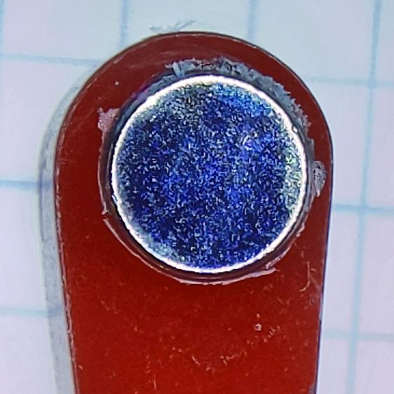
The fixtures worked well and aligned perfectly on the Sherline’s tooling plate. The 0.1 mm outset around the stops in the chipboard probably wasn’t needed, although the total repeatability seemed to be around 0.2 mm and pocket position errors are visible only on the smallest (red) stops:
Lathe Chuck Stops – misaligned pocket
All in all, this turned out pretty well. Next time will be even better!
#<chuckrad>=20.000                  (radius to center of magnet)
#<chuckjaws>=3                      (number of jaws)
#<chuckang>=[360.0/#<chuckjaws>]    (angle between jaws)

#<bitrad>=[2.900/2]                 (cutter radius)

#<pocketrad>=[4.100/2]              (magnet pocket radius)
#<pocketdeep>=2.200                 ( … depth)
#<xoffs>=[#<pocketrad>-#<bitrad>]   (pocket center to cutter center)

#<safez>=20.0                   (above all the clamps & gadgets)

G21 G54 G80 G90 G94             (metric!)

F600                            (full speed for the Sherline)

G0 Z#<safez>
Obviously, those magic numbers must match the laser-cut blanks, the magnets, the cutting bit in the spindle, the clamps on the table, the speed of the machine, and everything else you overlooked.
So. Much. Pain.
Knowing the angle to the current pocket, polar coordinate notation gets to the center point, with a jaunt in relative motion to the starting point for the helix into the pocket:
That dance produced rounder pockets with cleaner bottoms than just a single helix down and a straight pull upward.
Then set up for the next hole and clean up after the last one:
G0 @#<chuckrad> ^#<ang>         (back to center)
G0 Z#<safez>

#<ang>=[#<ang>+#<chuckang>]     (set up next hole)
O100 ENDREPEAT

G0 Z[2*#<safez>]
G0 X0 Y0

M2
I ran the Sherline XY axes at their 600 mm/min top speed, the spindle at 10 kRPM with a shiny new 3 mm (nominal!) cutter, ramped into the helix at ≅10° (on a 1 mm circle!), and it sliced the acrylic into nice chips without getting all melty.
Unlike with Javascript, when you get something wrong in G-Code, you can hear the crash.
The LinuxCNC pocketing code as a GitHub Gist:
This file contains hidden or bidirectional Unicode text that may be interpreted or compiled differently than what appears below. To review, open the file in an editor that reveals hidden Unicode characters.
Learn more about bidirectional Unicode characters
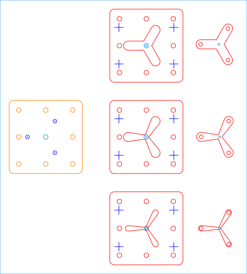
Because it need not withstand much lateral force and will get used only a dozen-ish times, the base is MDF and the stop alignment happens in three matching chipboard layers:
Lathe Chuck Stops – Pocketing Fixture – LB layout
The three stops (over on the right) are copy-pasta from the originals. A 0.1 mm outset in the chipboard (center) lets the acrylic shapes drop into the chipboard sheets with Good Enough™ alignment accuracy. The MDF layer (left) provides some overshoot comfort below the chipboard.
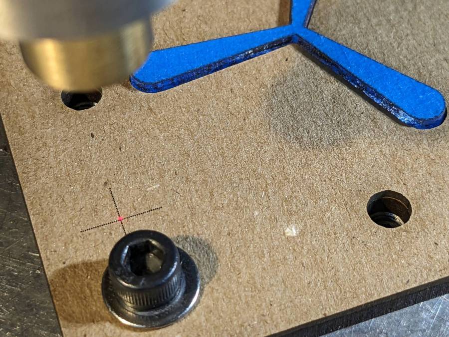
The chipboard layers each have four alignment targets at (±30,±20):
Lathe Chuck Stops – pocketing fixture touchoff
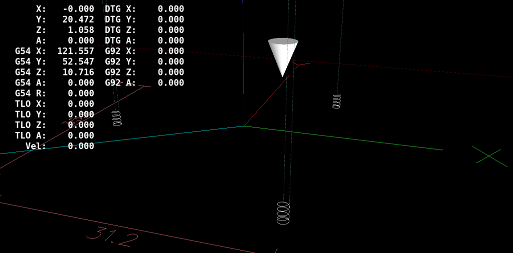
Touch off the lower-left target at (-30,-20) and G0 X30 Y30 should drop the laser dot in the middle of the upper-right target. With the (0,0) origin at the geometric center of the stop, LinuxCNC’s polar notation picks out the three pockets:
G0 @20 ^-60
G0 @20 ^180
G0 @20 ^60
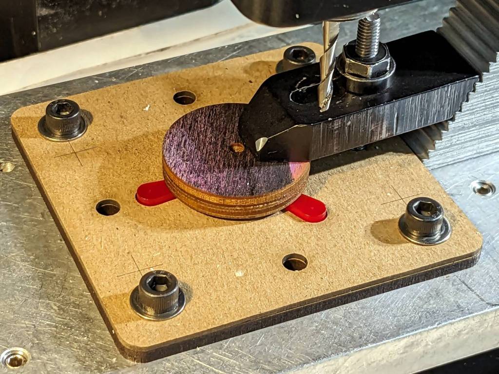
The plywood disk under the Sherline’s clamp has a glued ring to put the clamping force out near the ends of the legs. I started with just the aluminum clamp, but the legs needed a bit more stability; a laser cutter makes impromptu widgets like that trivially easy.


