
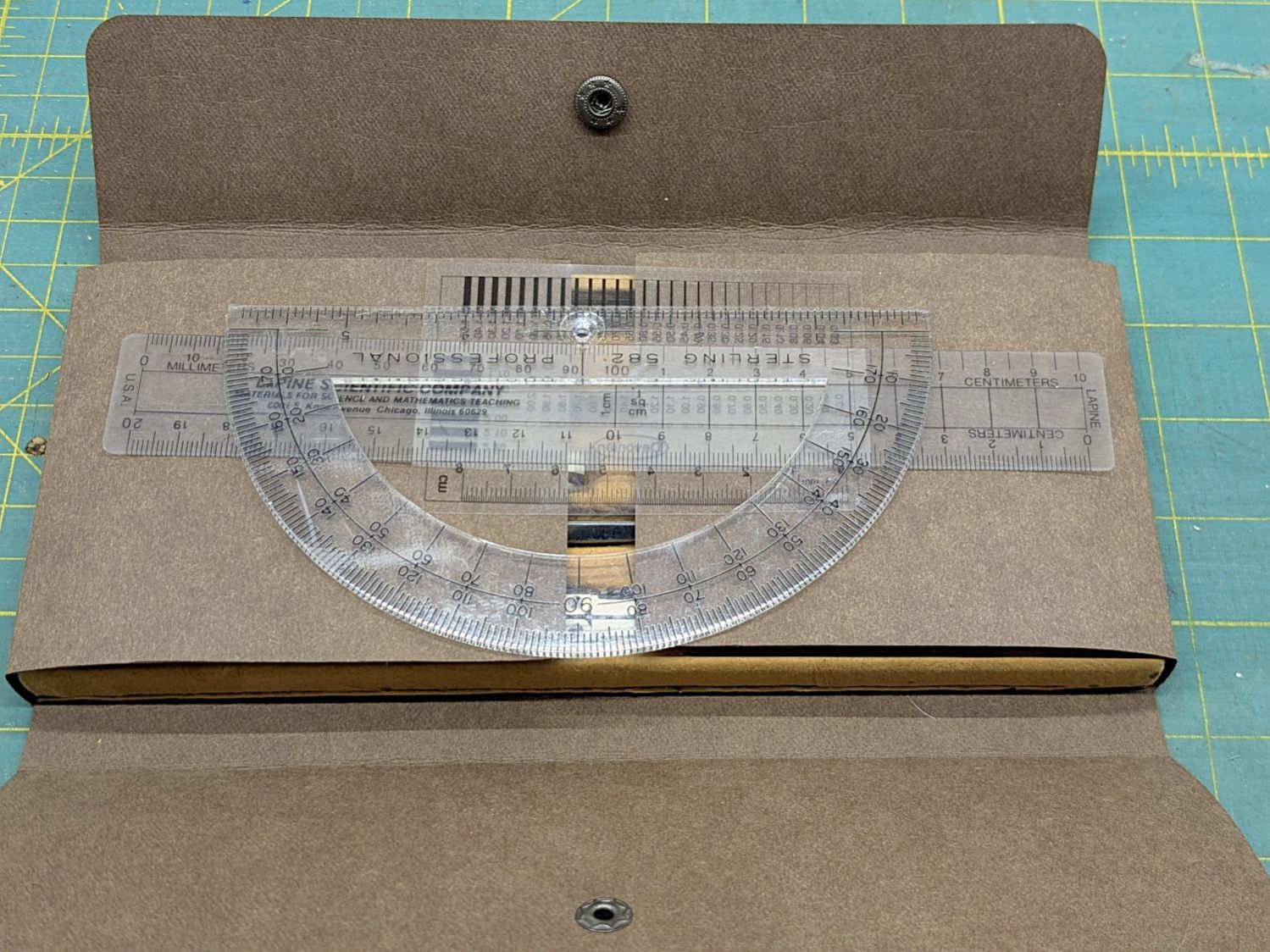
Our Young Engineer recently rebuilt the cover of a “vintage” drawing kit, with fabric pockets for protractors & scales and real leather hinges, thereby raising a long-procrastinated project to the top of my to-do list:
I know my father used it when he took drafting after high school in 1929. His penmanship and drawing ability were up to par well before that.
The inside sports a TEC logo:
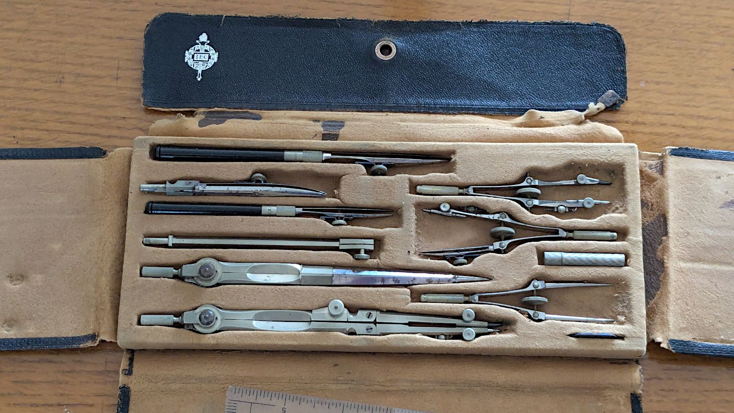
Some searching revealed it’s a No. 718 Drafting Set from the Technical Supply Company of Scranton and appeared in their 1913 catalog:

The printing on the inside of the flap differs, but the logo has TEC in the middle.
My father did not attend college and, in the teeth of The Great Depression, $26.50 was certainly too spendy for his family:
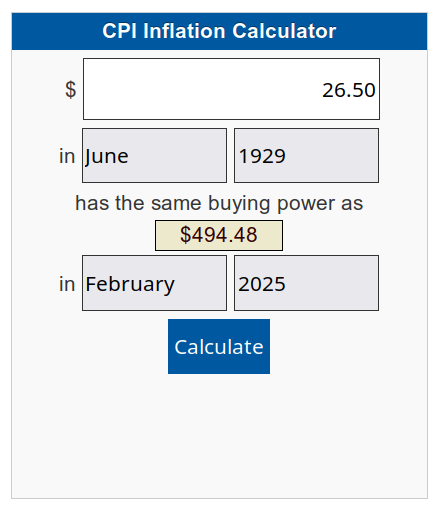
When the catalog was printed in 1913, No. 718 cost the equivalent of $862.82. Nowadays, similar sets once again cost about twenty bucks on eBay, which tells you something about economics.
None of that information changes what I know.
Having recently touched a roll of Kraft-Tex while shelving some boxes, this seemed reasonable:
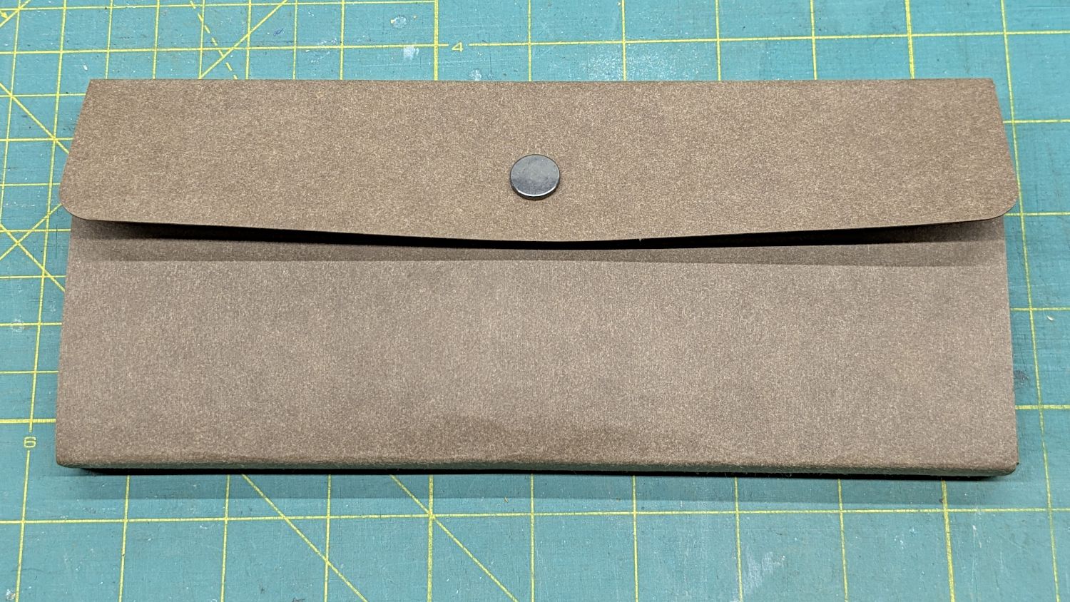
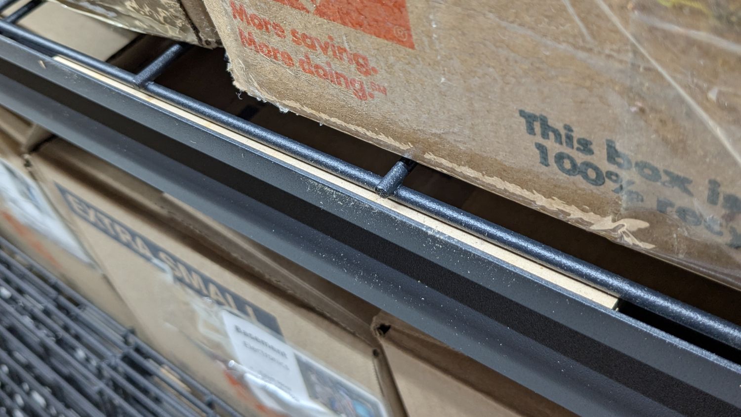
It lacks pockets for the tools I’ve added:
In retrospect, I should have used two leather snaps, but three would be excessive.
I folded the Kraft-Tex flat across a steel scale to make the first folds around the base, then finger-crimped folds at the top of the base with subsequent crisping around the scale:

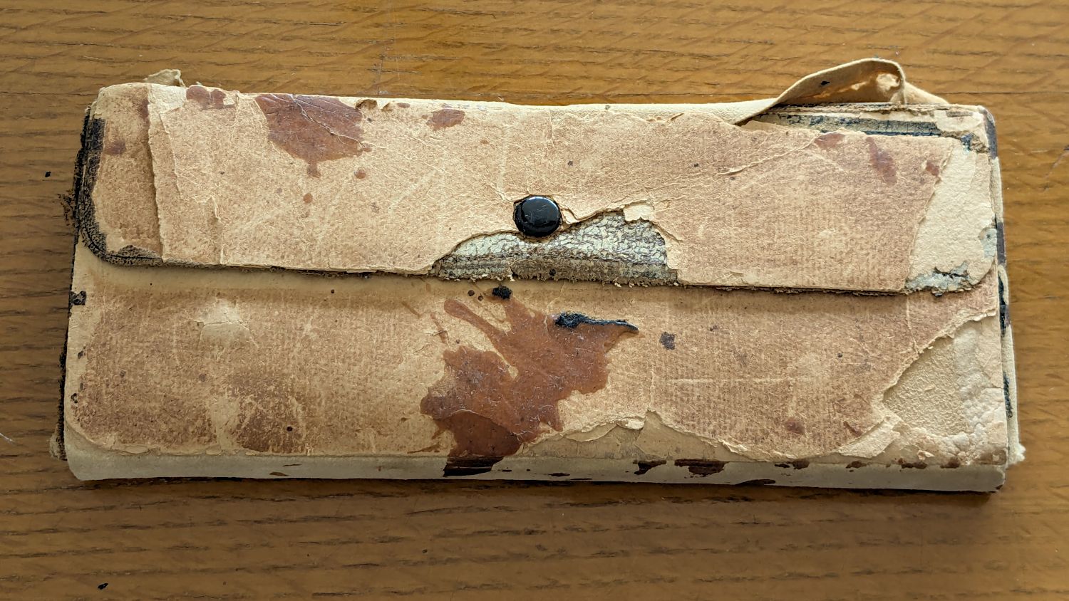
The underside of the original case seemed stable:
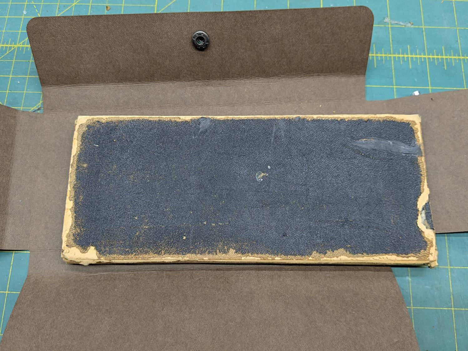
This may be sacrilege, but I saw no point in peeling the bottom just to cover it up,so I stuck the Kraft-Tex in place with a rectangle of adhesive sheet.
It doesn’t look the same, but it still gives me a warm feeling.
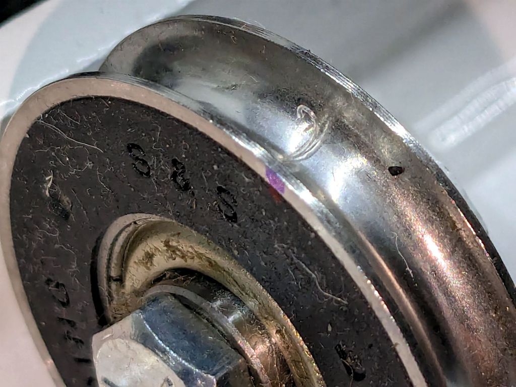
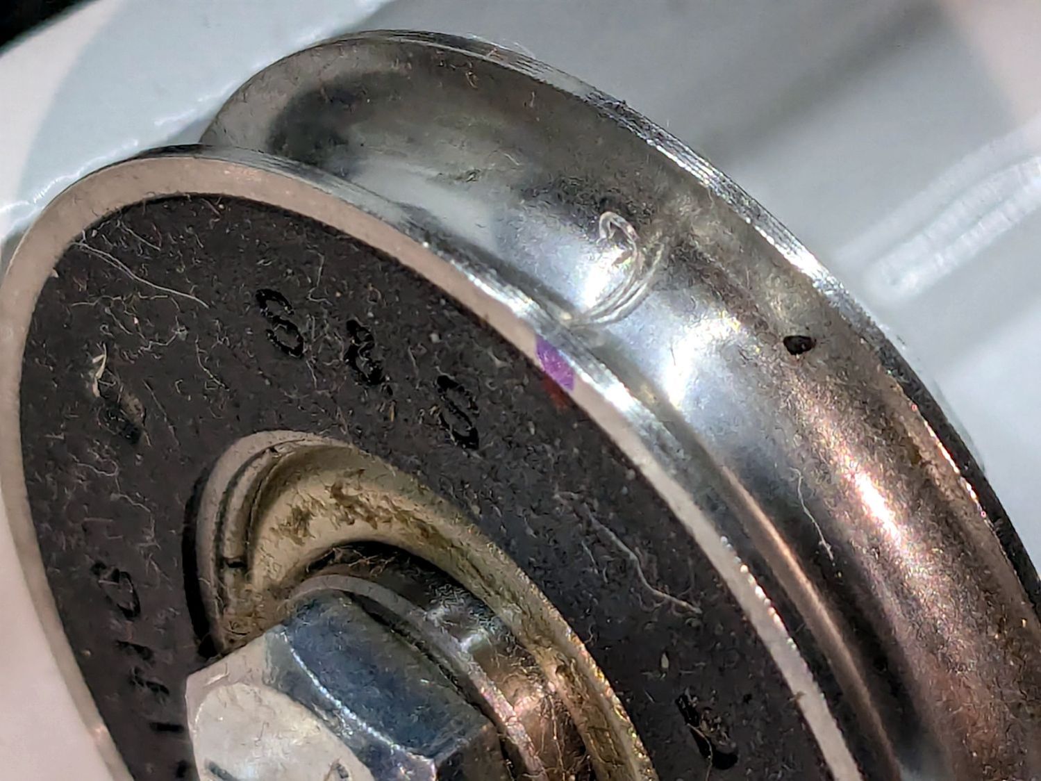
It still has the tiny wrench needed to adjust all its screws:

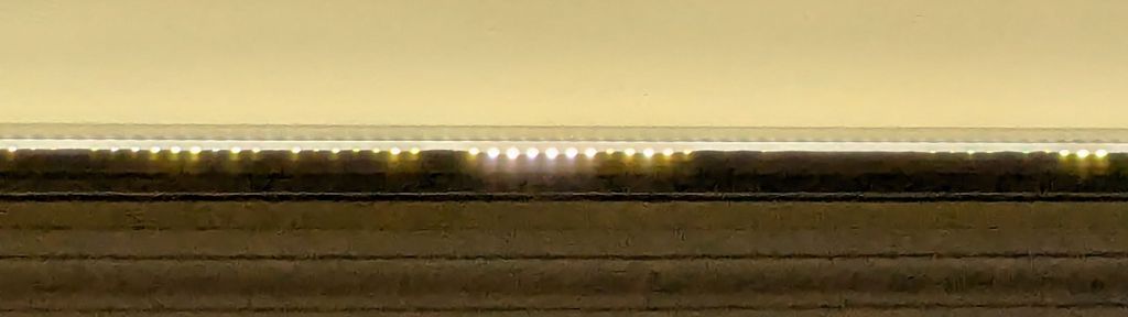
It’s on 0.1 inch graph paper and is 40 mil = 1 mm thick, should you want to make your own. The blades taper down to essentially a knife edge, which is why it’s made from hard blue steel.
I remember being fascinated by that little pig when I was a pup.
Putting some scraps to good use, I stuck a cushion in the anvil for the next time I punch down a leather snap:

The LightBurn SVG layout as a GitHub Gist:


