The Smell of Molten Projects in the Morning

Ed Nisley's Blog: Shop notes, electronics, firmware, machinery, 3D printing, laser cuttery, and curiosities. Contents: 100% human thinking, 0% AI slop.

Category: Machine Shop

Mechanical widgetry

  • OMTech 60 W Laser: Engraving Wobbulation

    OMTech 60 W Laser: Engraving Wobbulation

    Continuing the experiments on Y axis wobbling produced this shaky engraving:

    Engraving - 100mm-s 0.25mm interval 9pct
    Engraving – 100mm-s 0.25mm interval 9pct

    The rectangle is 30×10 mm, with lines spaced 0.25 mm apart to simplify estimating distances (although I also have a measuring magnifier) and run at 100 mm/s to simplify converting distance to time. The lines alternate in direction, beginning with a left-to-right line at the bottom (which is bar-straight from the initial positioning move). The wobbles occur at the start of each line.

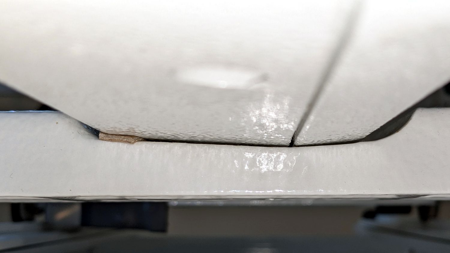
    A closer look with blown contrast:

    Engraving - 100mm-s 0.25mm interval 9pct - detail
    Engraving – 100mm-s 0.25mm interval 9pct – detail

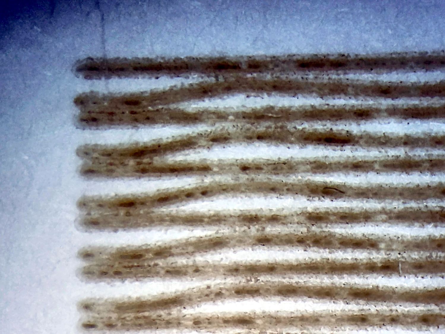
    The maximum error in the Y axis direction looks like 0.12 mm and damps out after 3 cycles. Each cycle covers 2.8 mm = 28 ms = 35 Hz.

    The LightBurn Preview shows a 1.5 mm overscan distance and extrapolating the wobbulations leftward suggests the gantry starts the scan line with an overshoot due to the Y axis motion. The cycle-to-cycle damping is about 50%, so the initial overshoot (invisible in the overscan region) might be 0.25 mm, agreeing reasonably well with the 0.2 mm seen while cutting small squares.

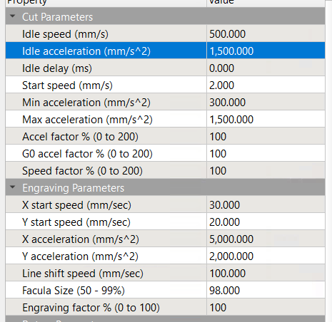
    The results above come from these settings:

    • Layer speed: 100 mm/s
    • Line interval: 0.25 mm
    • Y acceleration: 2000 mm/s²
    • Y start speed: 20 mm/s

    I then made single-variable changes to the Engraving Parameters settings:

    Line shift speed

    • 500 mm/s
    • 10 mm/s

    Y Acceleration

    • 200 mm/s²

    Y start speed

    • 30 mm/s

    Today I Learned: The Y Start Speed (in mm/s) for engraving is capped by the Y Axis Jumpoff Speed (in mm/s², so perhaps the maximum change in speed), which is, in turn, capped at 80 mm/s.

    Each of the variations produced a result visually indistinguishable from the image you see above: the error magnitude and oscillation frequency were identical.

      One possible reason: None of those settings have any effect, because LightBurn doesn’t do whatever the Ruida controller defines as Engraving. However, changing both the Y start speed and the Jumpoff speed should have made at least a little change to the results and did not.

      Another possible reason: Each 0.25 mm Y axis change requires 20.8 motor steps (either 20 or 21 at 12 µm/step), so the fancy tweaks lack space to take effect, the motor thumps 20-ish steps, and the gantry shakes the same way every time.

      The closer you look, the worse it gets …

    • OMTech 60 W Laser: Speed vs. Corner Radius Wobbulation

      OMTech 60 W Laser: Speed vs. Corner Radius Wobbulation

      Experimenting with little squares showed the Y axis has a definite wobble:

      Subpixel Zoo - Quattron RGBY Shifted - detail
      Subpixel Zoo – Quattron RGBY Shifted – detail

      Which suggested a simple test:

      Cornering - overview
      Cornering – overview

      I adjusted the laser power to compensate for the speed, with the result being a line burned into white cardboard. The lines are a bit under 0.2 mm wide, roughly the width of the focused spot.

      The controller settings for the X and Y axes:

      KT332N - X Y Axis Parameters - 2025-02-18
      KT332N – X Y Axis Parameters – 2025-02-18

      The acceleration values may be affected by the limits in this section:

      KT332N - Cut Engraving Parameters - 2025-02-18
      KT332N – Cut Engraving Parameters – 2025-02-18

      Assuming the Y axis acceleration is 3000 mm/s², the RepRap calculator shows the Y axis speeds within the 30 mm distance along the vertical sides:

      RepRap Accel Calculator - 3000mm-s2 30mm
      RepRap Accel Calculator – 3000mm-s2 30mm

      Extracting the useful bits and lining them up for comparison:

      Cornering - detail
      Cornering – detail

      The first column in the test results shows perfectly square corners have no problem at any speed, because the controller decelerates to nearly a stop before changing direction.

      Rounding the corner to 0.5 mm introduces a distinct wobble in the Y axis that doesn’t change much, probably because the controller still decelerates as it approaches the corner.

      The 1 mm radius corners show a distinct overshoot at all speeds. The peak overshoot doesn’t change much between 250 and 500 mm/s, because the RepRap calculator shows the machine barely reaches 250 mm/s by the middle of the side, so 500 mm/s isn’t any faster.

      The first overshoot is about 0.2 mm, the first undershoot is a little over 0.1 mm, and the rest are barely visible.

      The 2 and 4 mm radius corners have barely visible wobbles. Whether that is due to the head not flexing as much due to the lower acceleration around the larger radius I cannot say.

      The machine may not follow the simple RepRap acceleration profile when approaching a corner, let alone a rounded corner.

      I think attempting to reduce the overshoot by fiddling with the belt tension / hardware fasteners / whatever will be unavailing. The laser head runs on a linear rail along the gantry with plenty of unbalanced mass hanging off the bottom:

      OMTech 60W beam alignment - head X plane
      OMTech 60W beam alignment – head X plane

      Moving the beam 0.2 mm on the platform by pivoting around the rail 6 inch = 150 mm above amounts to only 0.08°, far less than anything I can measure while adjusting the mechanics.

      Slowing down doesn’t help nearly as much as I expected and rounding the corners makes it worse.

      Word has it that much spendier machines behave better, which is both comforting and unhelpful.

    • HQ Sixteen: Wheel Base Leveling

      HQ Sixteen: Wheel Base Leveling

      Trying out the Track Lock Blocks brought a long-standing puzzle to the surface: the left front wheel rode about a millimeter above its track, with the other three wheels carrying the weight of the machine. Neither that wheel nor the diagonally opposite wheel on the right rear worked well with the Blocks, because the machine rocked on the other two wheels.

      I initially thought the carriage rail under the machine was warped, but some poking and prodding showed the left front wheel rode higher than the others from front to back across the entire length of the table.

      So I loosened the screws holding the front wheel base plate to the machine and jacked up the front of the machine to get the wheels off their tracks:

      HQ Sixteen - track lock - jacking machine
      HQ Sixteen – track lock – jacking machine

      Then I jammed two strips of chipboard into the left side of the gap:

      HQ Sixteen - front wheel base plate shim
      HQ Sixteen – front wheel base plate shim

      I planned to use one long strip across the entire wheel base plate, but the screw holding the machine casting to the plate blocks the way, so it now has two shorter strips. Tightening the screws clamped the chipboard in place.

      The chipboard tilted the base plate and lowered the left wheel, with the right wheel surely moving slightly upward. Lowering the machine showed both front wheels now carry roughly the same load and the Track Lock Blocks now work the way I expected.

      After doing that, I found the recommended procedure in the official HQ Sixteen Service and Troubleshooting manual:

      HQ Sixteen - Wheel base shim procedure
      HQ Sixteen – Wheel base shim procedure

      The only “planed surface” around here is on the surface plate in the Basement Shop, two flights of stairs away, and I am not carrying either object to meet the other.

      In any event, I think the chipboard serves the same purpose as a simple washer, with advantage of a much larger bearing surface, so I’ll call it Good Enough until something else causes me to take the wheel base plate off.

    • HQ Sixteen: Track Lock Blocks

      HQ Sixteen: Track Lock Blocks

      Mary’s practice quilts on the HQ Sixteen suggest locking the machine’s wheels will simplify sewing a line parallel to the long edge of a quilt parallel to the table, but contemporary “Channel Locks” fit newer machines with larger wheels than on this one.

      Duplicating those rings in a smaller size seemed both difficult and not obviously functional, so I built a pair of blocks to capture the wheel on its track:

      HQ Sixteen - track lock - engaged
      HQ Sixteen – track lock – engaged

      The wheel sits in a recess holding it just barely above the track surface, so the (considerable) weight of the machine holds the block in place.

      Because lines on quilts have precise placement and Mary has quilting rulers within reach, the block measures exactly two inches from the point where it first touches the wheel to the center of the recess:

      HQ Sixteen - track lock - setup
      HQ Sixteen – track lock – setup

      She can then lay a ruler on the quilt, roll the machine front or back two inches, slide a block against each wheel, then roll the machine up a slight incline until the wheel drops into the recess:

      HQ Sixteen - track lock block - solid model
      HQ Sixteen – track lock block – solid model

      The spacing looks like this:

      HQ Sixteen - track lock block - solid model - show view
      HQ Sixteen – track lock block – solid model – show view

      The usual 3D printing process puts 0.2 mm steps along the ramp, but they’re almost imperceptible while rolling the machine:

      HQ Sixteen - track lock block - PrusaSlicer preview
      HQ Sixteen – track lock block – PrusaSlicer preview

      The ramp slope is all of 1:20 = 2.5°, so pulling / pushing the machine requires very little oomph.

      I put thin cloth tape (approximately friction tape, but with real adhesive) on the bottom of the block by the simple expedient of sticking it to the block and scissoring off the excess. A little compliance between the block and the track prevents the hard plastic shapes from sliding more easily than I’d like. If your tape is thicker than mine, knock a little off the WheelZ value.

      The OpenSCAD code can produce shapes to laser-cut an adhesive sheet, although stacking a foam sheet will definitely require height adjustment :

      HQ Sixteen - track lock block - glue sheet
      HQ Sixteen – track lock block – glue sheet

      The OpenSCAD source code as a GitHub Gist:

      // HQ Sixteen – wheel track lock block
      // Ed Nisley – KE4ZNU
      // 2025-02-14
      include <BOSL2/std.scad>
      Layout = "Show"; // [Show,Build,Glue,Track,Block,Wheel]
      /* [Hidden] */
      ID = 0;
      OD = 1;
      LENGTH = 2;
      Protrusion = 0.1;
      Windage = 0.1;
      WallThick = 5.0; // minimum wall thickness
      RailOD = 5.5; // rounded top of rail
      RailHeight = RailOD; // … flange to top
      RailBase = [100,2*15.7 + RailOD,3]; // … Y = flange width, arbitrary X & Z
      WheelOD = 38.0; // rail roller
      WheelMinor = 6.2; // … rail recess
      WheelWidth = 8.3 + 2*Windage; // … outer sides
      WheelZ = RailHeight + (WheelOD – WheelMinor)/2; // axle centerline wrt rail flange
      LockOC = 2.0*INCH; // engagement to lock recess
      GripLength = 20.0;
      BlockOA = [GripLength + WheelOD/2 + LockOC,WheelWidth + 2*WallThick,2*RailHeight];
      BlockRadius = 2.0;
      $fn = 12*3*4; // smooth outer perimeters
      //———-
      // Construct the pieces
      module Track(Len = 2*BlockOA.x) {
      zrot(90) back(Len/2) down(RailBase.z) xrot(90)
      linear_extrude(height=Len,convexity=5)
      rect([RailBase.y,RailBase.z],anchor=FRONT)
      attach(BACK,FRONT) rect([RailOD,RailHeight – RailOD/2])
      attach(BACK) circle(d=RailOD);
      }
      module Wheel(Len = WheelWidth) {
      xrot(90)
      difference() {
      cylinder(d=WheelOD,h=Len,center=true);
      torus(r_maj=WheelOD/2,d_min=WheelMinor);
      }
      }
      module Block() {
      difference() {
      left(GripLength + WheelOD/2)
      cuboid(BlockOA,anchor=LEFT + BOTTOM,rounding=BlockRadius,except=BOTTOM);
      Track();
      up(WheelZ) xrot(90)
      cylinder(d=WheelOD,h=WheelWidth,center=true);
      right(LockOC)
      up(WheelZ – WheelOD/2) yrot(atan((RailHeight – WheelMinor/2)/LockOC))
      cuboid([LockOC,WheelWidth,BlockOA.z],anchor=RIGHT+BOTTOM);
      }
      }
      //———-
      // Show & build the results
      if (Layout == "Block" || Layout == "Build")
      Block();
      if (Layout == "Track")
      Track();
      if (Layout == "Wheel")
      Wheel();
      if (Layout == "Glue")
      projection(cut=true)
      Block();
      if (Layout == "Show") {
      color("SteelBlue")
      Block();
      for (i=[0,1])
      right(i*LockOC)
      color("Silver",0.7)
      up(WheelZ) Wheel();
      color("White",0.5)
      Track();
      }

    • Drive Wheelchair Foot Rest Lubrication

      Drive Wheelchair Foot Rest Lubrication

      After few days in the Drive Blue Streak wheelchair, I finally lubricated the foot rest pivots:

      Drive wheelchair foot rest lubrication
      Drive wheelchair foot rest lubrication

      The complex molded rests gripped their metal tubes so tightly as be nearly immovable, but one drop of Kroil at the four obvious spots let them turn much more easily.

      The flange overlapping the upright tube along the bottom of the picture hits the short protrusion and holds the rest parallel to the floor. A screw at the plastic cap near the top keeps the rests from working their way too far from the upright tube.

      I can make it to the Basement Shop™ and back, paying careful attention to detail.

    • HQ Sixteen: Handi Feet Conversion

      HQ Sixteen: Handi Feet Conversion

      Mary wanted a Ruler Foot (a.k.a. Handi Feet Sure Foot) on her Handi Quilter HQ Sixteen sewing machine, which required removing the original foot, installing the Handi Feet Conversion Kit, then adjusting the foot height above the needle plate:

      HQ Sixteen Handi-feet conversion - Sure-foot installed
      HQ Sixteen Handi-feet conversion – Sure-foot installed

      The Conversion Kit instructions repeatedly recommend hauling the machine to your local Handi Quilter authorized dealer / repair center, which would be an hour’s drive away. Suffice it to say I’m both authorized by a suitable authority and a dab hand with a hex wrench: I can do this thing.

      The original foot is a welded assembly with an M5×0.8 screw thread matching the leftmost (darker) rod on the machine:

      HQ Sixteen Handi-feet conversion - original foot
      HQ Sixteen Handi-feet conversion – original foot

      It’s sitting atop the label of the Sure Foot kit with a picture of the ruler foot.

      Although the instructions suggest you can install the conversion kit without removing the machine cover, I wanted to see what was going on in there and verify everything fit properly:

      HQ Sixteen Handi-feet conversion - foot rod clamp
      HQ Sixteen Handi-feet conversion – foot rod clamp

      As above, the foot / adapter screws into the left rod, with the rectangular aluminum clamp attached to the follower riding the cam near the top of the machine. The rod slides on the greasy pin absorbing the torque from the follower.

      I had to loosen the clamp, slide the rod upward, unscrew the original foot, install the adapter, adjust the rod position for the proper 0.5 mm spacing between ruler foot and the needle plate at bottom dead center, then tighten the screw. The disturbed grease above the block reveals I moved the rod upward about 8 mm through that block during the process; it now sits lower, just a few millimeters above where the factory tech assembled it for the original foot.

      The top photo shows half a dozen threads between the top of the adapter and the bottom of the jam nut. Without adjusting the rod position in the clamp, the adapter screw threads are the only way to adjust the foot-to-plate space: each full turn moves the foot 0.8 mm. I screwed the adapter completely into the rod, then backed it out three turns to leave enough adjustment for other feet and fabrics.

      The machine cover has a hole providing access to the clamp screw, so, in principle, you can stick a hex wrench in there to loosen / tighten the clamp while making fine adjustments in the foot position, all without removing the cover. If one full turn of the adapter doesn’t set the right position, I highly recommend removing the machine cover to see what you’re doing.

      We then installed the Ruler Base on the machine, which required removing the preinstalled Medium fuzzy spacer strips, and all’s well that ends well.

    • Laser-Engraved CD Stress Cracking

      Laser-Engraved CD Stress Cracking

      Given the cracking caused by vector patterns on CDs and DVDs, seeing stress cracks open up on large-area engravings came as no surprise:

      Laser engraved CD cracking - D
      Laser engraved CD cracking – D

      They start smaller in the more closely engraved areas:

      Laser engraved CD cracking - A
      Laser engraved CD cracking – A

      But eventually spread over the entire surface:

      Laser engraved CD cracking - C
      Laser engraved CD cracking – C

      They’re not always straight:

      Laser engraved CD cracking - B
      Laser engraved CD cracking – B

      And aren’t aligned with the engraving path:

      Laser engraved CD cracking - B detail
      Laser engraved CD cracking – B detail

      My threat model says those discs are definitely unreadable …