The Smell of Molten Projects in the Morning

Ed Nisley's Blog: Shop notes, electronics, firmware, machinery, 3D printing, laser cuttery, and curiosities. Contents: 100% human thinking, 0% AI slop.

Category: Machine Shop

Mechanical widgetry

  • Automated Cookie Cutters: Fine Tuning

    TuxTrace - grayscale height map
    TuxTrace – grayscale height map

    Running more grayscale images through the cookie cutter process revealed some problems and solutions…

    It seems OpenSCAD (or the underlying CGAL library) chokes while creating a 3D surface from a bitmap image more than about 350-ish pixels square: it gradually blots up all available memory, fills the entire swap file, then crashes after a memory allocation failure. As you might expect, system response time rises exponentially and, when the crash finally occurs, everything else resides in the swap file. The only workaround seems to be keeping the image under about 330-ish pixels. That’s on a Xubuntu 12.04 box with 4 GB of memory and an 8 GB swap partition.

    So I applied 2.5 pixel/mm scaling factor to images intended for a 5 inch build platform:

    317 pixel = (5 inch × 25.4 mm/inch) * 2.5 pixel/mm

    Any reasonable scaling will work. For smaller objects or platforms, use 3 pixel/mm or maybe more. If you have a larger build platform, scale accordingly. I baked the default 2.5 factor into the Bash script below, but changing it in that one spot will do the trick. Remember that you’re dealing with a 0.5 mm extrusion thread and the corresponding 1 mm minimum feature size, so the ultimate object resolution isn’t all that great.

    Tomorrow I’ll go through an image preparation checklist. However, given a suitable grayscale height map image as shown above, the rest happens automagically:

    ./MakeCutter.sh filename.png

    That process required some tweakage, too …

    TuxTrace-press - solid model
    TuxTrace-press – solid model
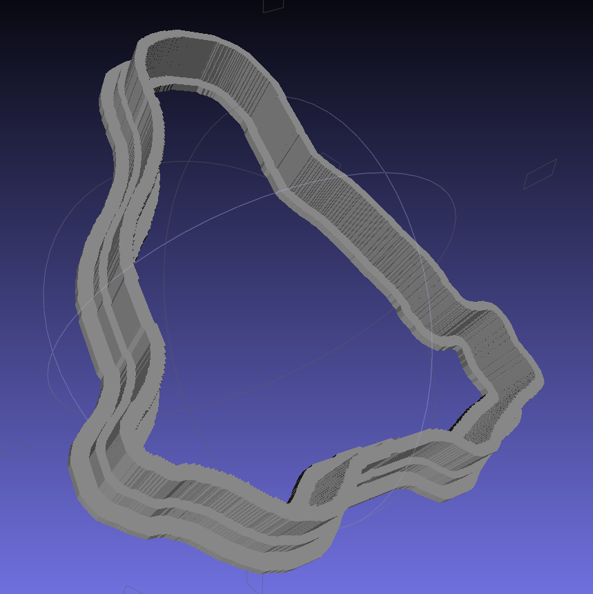
    TuxTrace-cutter - solid model
    TuxTrace-cutter – solid model

    Auto-cropping the image may leave empty borders: the canvas remains at the original size with the cropped image floating inside. Adding +repage to the convert command shrinkwraps the canvas around the cropped image.

    If the JPG file of the original scanned image has an embedded comment (Created by The GIMP, for example), then so will the PNG file and so will the ASCII PGM files, much to my astonishment and dismay. The comment line (# Created by The GIMP) screwed up my simplistic assumption about the file’s header four-line header layout. The +set Comment squelches the comment; note that the word Comment is a keyword for the set option, not a placeholder for an actual comment.

    It turns out that OpenSCAD can export STL files that give it heartburn when subsequently imported, so I now process the height map and outline images in the same OpenSCAD program, without writing / reading intermediate files. That requires passing all three image dimensions into the program building the cutter and press, which previously depended on the two incoming STL files for proper sizing. This seems much cleaner.

    The original program nested the cookie press inside the cutter on the build platform as a single STL file, but it turns out that for large cutters you really need a T-shaped cap to stabilize the thin plastic shape; the press won’t fit inside. The new version produces two separate STL files: one for the press and one for the cutter, in two separate invocations. The command-line options sort everything out on the fly.

    Because the cutter lip extends outward from the press by about 6 mm, you must size the press to keep the cutter completely on the build platform. The 5 inch outline described above produces a cutter that barely fits on a 5.5 inch platform; feel free to scale everything as needed for your printer.

    The time commands show that generating the press goes fairly quickly, perhaps 5 to 10 minutes on a 3 GHz Core 2 Duo 8400. The multiple Minkowski operations required for the cutter, however, run a bit over an hour on that machine. OpenSCAD saturates one CPU core, leaving the other for everything else, but I wound up getting a cheap off-lease Dell Optiplex 760 as a headless graphics rendering box because it runs rings around my obsolete Pentium D desktop box.

    The MakeCutter.sh Bash script controlling the whole show:

    #!/bin/bash
    DotsPerMM=2.5
    MapHeight=5
    ImageName="${1%%.*}"
    rm ${ImageName}_* ${ImageName}-press.stl ${ImageName}-cutter.stl
    echo Normalize and prepare grayscale image...
    convert $1 -type Grayscale -depth 8 -auto-level -trim +repage -flip -flop -negate +set Comment ${ImageName}_prep.png
    echo Create PGM files...
    convert ${ImageName}_prep.png -compress none ${ImageName}_map.pgm
    convert ${ImageName}_prep.png -white-threshold 1 -compress none ${ImageName}_plate.pgm
    echo Create height map data files...
    ImageX=`identify -format '%[fx:w]' ${ImageName}_map.pgm`
    ImageY=`identify -format '%[fx:h]' ${ImageName}_map.pgm`
    echo Width: ${ImageX} x Height: ${ImageY}
    cat ${ImageName}_map.pgm | tr -s ' \012' '\012' | tail -n +5 | column -x -c $((8*$ImageX)) > ${ImageName}_map.dat
    cat ${ImageName}_plate.pgm | tr -s ' \012' '\012' | tail -n +5 | column -x -c $((8*$ImageX)) > ${ImageName}_plate.dat
    echo Create cookie press...
    time openscad -D BuildPress=true \
    -D fnPlate=\"${ImageName}_plate.dat\" \
    -D fnMap=\"${ImageName}_map.dat\" -D Height=$MapHeight \
    -D ImageX=$ImageX -D ImageY=$ImageY -D DotsPerMM=$DotsPerMM \
    -o ${ImageName}-press.stl Cookie\ Cutter.scad
    echo Create cookie cutter...
    time openscad -D BuildCutter=true \
    -D fnPlate=\"${ImageName}_plate.dat\" \
    -D ImageX=$ImageX -D ImageY=$ImageY -D DotsPerMM=$DotsPerMM \
    -o ${ImageName}-cutter.stl Cookie\ Cutter.scad
    

    The Cookie Cutter.scad OpenSCAD source code:

    // Cookie cutter from grayscale height map using Minkowski sum
    // Ed Nisley KE4ZNU - November 2012
    
    //-----------------
    // Cookie cutter files
    
    BuildPress = false;						// override with -D Buildxxx=true
    BuildCutter = false;
    
    fnMap = "no_map.dat";					// override with -D 'fnMap="whatever.dat"'
    fnPlate = "no_plate.dat";				// override with -D 'fnPlate="whatever.dat"'
    
    DotsPerMM = 2.5;						// overrride with -D DotsPerMM=number
    
    MapHeight = 5.0;						// overrride with -D MapHeight=number
    
    ImageX = 10;							// overrride with -D ImageX=whatever
    ImageY = 10;
    
    MapScaleXYZ = [1/DotsPerMM,1/DotsPerMM,MapHeight/255];
    PlateScaleXYZ = [1/DotsPerMM,1/DotsPerMM,1.0];
    
    echo("Press File: ",fnMap);
    echo("Plate File: ",fnPlate);
    
    echo("ImageX:",ImageX," ImageY: ", ImageY);
    echo("Map Height: ",MapHeight);
    echo("Dots/mm: ",DotsPerMM);
    echo("Scale Map: ",MapScaleXYZ,"  Plate: ",PlateScaleXYZ);
    
    //- Extrusion parameters - must match reality!
    
    ThreadThick = 0.25;
    ThreadWidth = 2.0 * ThreadThick;
    
    //- Cookie cutter parameters
    
    TipHeight = IntegerMultiple(8.0,ThreadThick);		// cutting edge
    TipWidth = 5*ThreadWidth;
    
    WallHeight = IntegerMultiple(4.0,ThreadThick);		// center section
    WallWidth = IntegerMultiple(4.0,ThreadWidth);
    
    LipHeight = IntegerMultiple(2.0,ThreadThick);		// cutter handle
    LipWidth = IntegerMultiple(3.0,ThreadWidth);
    
    PlateThick = IntegerMultiple(4.0,ThreadThick);	// solid plate under press relief
    
    //- Useful info
    
    function IntegerMultiple(Size,Unit) = Unit * ceil(Size / Unit);
    
    Protrusion = 0.1;						// make holes & unions work correctly
    
    MaxConvexity = 5;						// used for F5 previews in OpenSCAD GUI
    
    ZFuzz = 0.2;							// numeric chaff just above height map Z=0 plane
    
    //-----------------
    // Import plate height map, slice off a slab to define outline
    
    module Slab(Thick=1.0) {
    	intersection() {
    		translate([0,0,Thick/2])
    			cube([2*ImageX,2*ImageY,Thick],center=true);
    		scale(PlateScaleXYZ)
    			difference() {
    				translate([0,0,-ZFuzz])
    					surface(fnPlate,center=true,convexity=MaxConvexity);
    				translate([0,0,-1])
    					cube([2*ImageX,2*ImageY,2],center=true);
    			}
    	}
    }
    
    //- Put peg grid on build surface
    
    module ShowPegGrid(Space = 10.0,Size = 1.0) {
    
    	Range = floor(50 / Space);
    
    	for (x=[-Range:Range])
    	  for (y=[-Range:Range])
    		translate([x*Space,y*Space,Size/2])
    			%cube(Size,center=true);
    }
    
    //- Build it
    
    //ShowPegGrid();
    
    if (BuildPress) {
    	echo("Building press");
    	union() {
    		Slab(PlateThick + Protrusion);
    		translate([0,0,PlateThick])							// cookie press height map
    			scale(MapScaleXYZ)
    			difference() {
    				translate([0,0,-ZFuzz])
    					surface(fnMap,center=true,convexity=MaxConvexity);
    				translate([0,0,-1])
    					cube([2*ImageX,2*ImageY,2],center=true);
    			}
    	}
    }
    
    if (BuildCutter) {
    	echo("Building cutter");
    	union() {
    		difference() {
    			union() {										// stack cutter layers
    				translate([0,0,(WallHeight + LipHeight - 1)])
    					minkowski() {
    						Slab(TipHeight);
    						cylinder(r=TipWidth,h=1);
    					}
    				translate([0,0,LipHeight - 1])
    					minkowski() {
    						Slab(WallHeight);
    						cylinder(r=WallWidth,h=1);
    					}
    			}
    			translate([0,0,-1])								// punch central hole for plate
    				Slab(TipHeight + WallHeight + LipHeight + 2);
    		}
    		minkowski() {										// put lip around base
    			difference() {
    				minkowski() {
    					Slab(LipHeight/3);
    					cylinder(r=WallWidth,h=LipHeight/3);
    				}
    				translate([0,0,-2*LipHeight])
    					Slab(4*LipHeight);
    			}
    			cylinder(r=LipWidth,h=LipHeight/3);
    		}
    	}
    }
    

    And then it Just Works…
  • Propane Tank QD Adapter Tool

    Although it’s common practice to exchange your empty 20 pound propane tank for a full one, I vastly prefer to keep my own tanks: I know where they’ve been, how they’ve been used, and can be reasonably sure they don’t have hidden damage. Two of my tanks have old-style threaded connections, but the barby has a quick-disconnect fitting on the regulator and I’ve been using an adapter on those tanks.

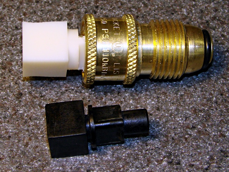
    The adapter comes with a plastic tool that you use to install it in the tank valve. In principle, you insert the tool into the adapter, thread the adapter into the valve, then tighten with a wrench until the neck of the plastic tool snaps, at which point you eject the stub and the adapter becomes permanently installed. I don’t like permanent, so I carefully tightened the adapter to the point where the O-ring seals properly and the tool didn’t quite break. I’ve always wanted a backup tool, just in case the original broke, and now I have one:

    Propane QD Adapter Tool - in adapter
    Propane QD Adapter Tool – in adapter

    It fit into both the adapter body and the 5/8 inch wrench (the OEM tool is 9/16 inch) without any fuss at all:

    Propane QD Adapters - OEM and printed
    Propane QD Adapters – OEM and printed

    The solid model has a few improvements over the as-printed tool above:

    • Shorter wrench flats
    • More durable protrusions to engage the locking balls
    Propane QD Adapter Tool
    Propane QD Adapter Tool

    It took about an hour to design and another 45 minutes to print, so it’s obviously not cost-effective. I’ll likely never print another, but maybe you will.

    The OpenSCAD source code:

    // Propane tank QD connector adapter tool
    // Ed Nisley KE4ZNU November 2012
    
    include </mnt/bulkdata/Project Files/Thing-O-Matic/MCAD/units.scad>
    include </mnt/bulkdata/Project Files/Thing-O-Matic/Useful Sizes.scad>
    
    //- Extrusion parameters must match reality!
    //  Print with +1 shells and 3 solid layers
    
    ThreadThick = 0.25;
    ThreadWidth = 2.0 * ThreadThick;
    
    HoleWindage = 0.2;
    
    function IntegerMultiple(Size,Unit) = Unit * ceil(Size / Unit);
    
    Protrusion = 0.1;			// make holes end cleanly
    
    //----------------------
    // Dimensions
    
    WrenchSize = (5/8) * inch;		// across the flats
    WrenchThick = 10;
    
    NoseDia = 8.6;
    NoseLength = 9.0;
    
    LockDia = 12.5;
    LockRingLength = 1.0;
    LockTaperLength = 1.5;
    
    TriDia = 15.1;
    TriWide = 12.2;										// from OD across center to triangle side
    TriOffset = TriWide - TriDia/2;		// from center to triangle side
    TriLength = 9.8;
    
    NeckDia = TriDia;
    NeckLength = 4.0;
    
    //----------------------
    // Useful routines
    
    module PolyCyl(Dia,Height,ForceSides=0) {			// based on nophead's polyholes
    
    Sides = (ForceSides != 0) ? ForceSides : (ceil(Dia) + 2);
    
    FixDia = Dia / cos(180/Sides);
    
    cylinder(r=(FixDia + HoleWindage)/2,
    h=Height,
    	   $fn=Sides);
    }
    
    module ShowPegGrid(Space = 10.0,Size = 1.0) {
    
    Range = floor(50 / Space);
    
    	for (x=[-Range:Range])
    	  for (y=[-Range:Range])
    		translate([x*Space,y*Space,Size/2])
    		  %cube(Size,center=true);
    
    }
    
    //-------------------
    // Build it...
    
    $fn = 4*6;
    
    ShowPegGrid();
    
    union() {
    
    	translate([0,0,(WrenchThick + NeckLength + TriLength - LockTaperLength - LockRingLength + Protrusion)])
    		cylinder(r1=NoseDia/2,r2=LockDia/2,h=LockTaperLength);
    
    		translate([0,0,(WrenchThick + NeckLength + TriLength - LockRingLength)])
    		cylinder(r=LockDia/2,h=LockRingLength);
    
    	difference() {
    		union() {
    
    			translate([0,0,WrenchThick/2])
    				cube([WrenchSize,WrenchSize,WrenchThick],center=true);
    
    			cylinder(r=TriDia/2,h=(WrenchThick + NeckLength +TriLength));
    
    			cylinder(r=NoseDia/2,h=(WrenchThick + NeckLength + TriLength + NoseLength));
    		}
    
    		for (a=[-1:1]) {
    			rotate(a*120)
    				translate([(TriOffset + WrenchSize/2),0,(WrenchThick + NeckLength + TriLength/2 + Protrusion/2)])
    					cube([WrenchSize,WrenchSize,(TriLength + Protrusion)],center=true);
    		}
    	}
    }
    
  • Waterproof RGB LED Strip

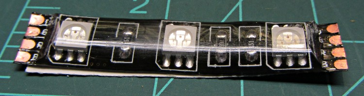
    Another package from halfway around the planet brought 5 meters of waterproof RGB LED strip, which may be useful for projects like longboard lighting. Not having worked with a waterproof strip before, I snipped off a segment:

    Waterproof RGB LED Strip - one segment
    Waterproof RGB LED Strip – one segment

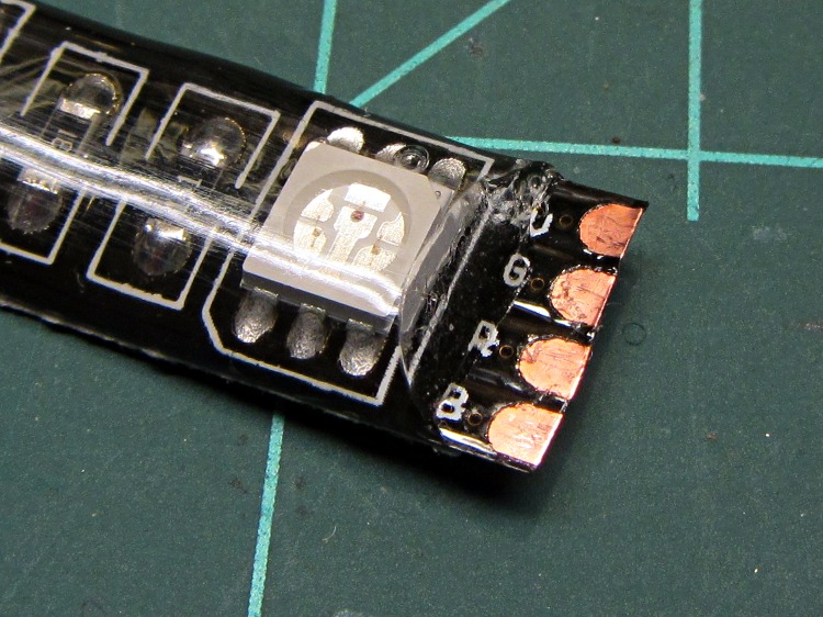
    The waterproof coating seems to be a soft silicone or acrylic pour with roughly the consistency of Gummy Bear tummy, so cutting it off requires a delicate touch to avoid slicing the flex circuit board:

    Waterproof RGB LED Strip - peeled top
    Waterproof RGB LED Strip – peeled top

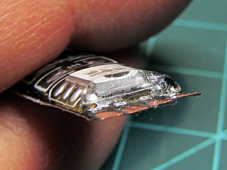
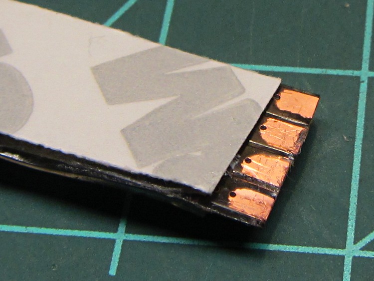
    It doesn’t actually bond to the circuit board, though, and if you get a sharp blade underneath, can be peeled away. I suspect this means water will eventually make its way into the circuitry and you shouldn’t expect to submerge the strip in a fish tank. I scraped the contacts clean, which probably isn’t the right way to do it:

    Waterproof RGB LED Strip - end view
    Waterproof RGB LED Strip – end view

    The underside makes no pretension of being waterproof and you can peel / roll / rub the adhesive off the contacts:

    Waterproof RGB LED Strip - peeled bottom
    Waterproof RGB LED Strip – peeled bottom

    Does anyone else doubt the authenticity of that 3M logo? The production values look rather low, but maybe it’s just me.

    The trouble with soldering contacts to the bottom is the ensuing lump that prevents good adhesive bonding. The trouble with soldering contacts on the top is the surgery required to remove the coating. You can get punch-through contacts with snake-bite fangs, but even the vendors admit to about a 20% failure rate, which implies it’s pretty much a crapshoot.

  • Braided Wind Chime

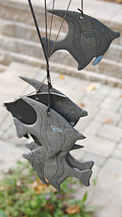
    Fish Wind Chime
    Fish Wind Chime

    A few days of high & gusty winds braided the cords of the aluminum fish school wind chime hanging over the end of the patio:

    It’s obviously an old, much-repaired relic.

    My Shop Assistant added those blue fins many years ago, quite some time after she and a friend lost one of the fish while using them as digging implements. An unmarked replacement fish, crudely bandsawed from black-coated aluminum, began swimming in stealth mode amid the school.

    Sometimes it’s not the object, it’s the memories…

  • Pull Tab Cord Replacement

    The braided cord on the NSA pull tab dangling from my belt pack has a monofilament core:

    Worn tab cord
    Worn tab cord

    The Basement Laboratory Warehouse Wing doesn’t have an exact replacement, but braided nylon fishing line should come close:

    Pull tab - braided nylon line
    Pull tab – braided nylon line

    If I keep a closer watch on the situation, maybe I can replace the cord before the tab goes missing…

  • Magnesium Water Heater Anode Rod: Seven Years Later

    There never seems to be a good time to drain your water heater and check the anode rod, but I finally found a Round Tuit…

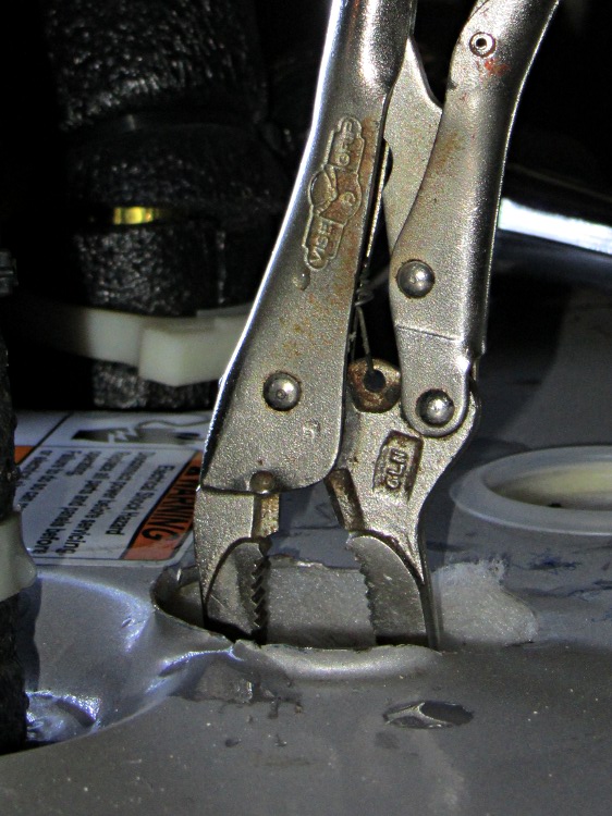
    Pursuant to that comment, I drained a few gallons before applying the six-point 1-1/16 inch socket and loosening the anode rod without fuss or bother. I couldn’t get a good finger grip on the bolt head inside the enlarged hole, but a long-nose Vise-Grip pliers did the trick:

    Gripping anode rod bolt
    Gripping anode rod bolt

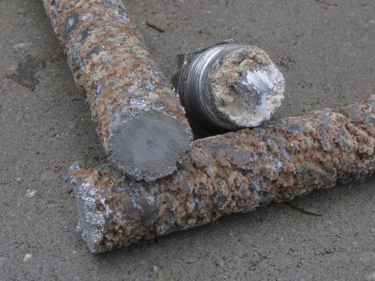
    The first look showed a solid bar of corrosion:

    Anode rod emerging
    Anode rod emerging

    You can see the 3/4 inch socket wrench in the background: I didn’t need the breaker bar this time!

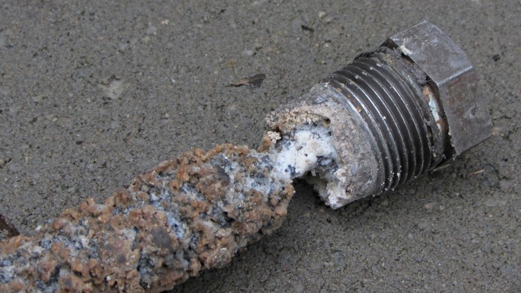
    The magnesium anode rod corroded down to the steel core wire just under the bolt head:

    Anode rod - bolt
    Anode rod – bolt

    The entire rod was about half a foot shorter than the new one, but I cannot tell whether that much corroded away or rods have gotten longer (they’ve certainly gotten more expensive):

    Anode rod - tip
    Anode rod – tip

    I sawed the rod to get it out of the heater, because I also wanted to see how much magnesium remained inside the corrosion. Quite a lot, as it turned out, so I suppose I could have reinstalled the rod and left it for another few years:

    Anode rod - cut ends
    Anode rod – cut ends

    I don’t know where all the corrosion products went, because the water heater drained uneventfully, without clogging the valve or depositing a pile of crud at the end of the hose. There were a few particles, but nothing like the residue from the aluminum rod.

    Then I cleaned off a new magnesium rod, tilted the water heater to get enough clearance, installed the rod with a wrap of PTFE tape, and reinstalled the water supply lines. I suspect the next owners of the place will be looking at it a decade down the calendar…

    If I had more guts and less sense, I’d chuck the bar stubs in the lathe and turn off the corrosion to get some nice steel-core magnesium rods. The prospect of extinguishing a magnesium fire in the basement doesn’t entice me in the least.

  • 30 Year Clock: The Janus Movement

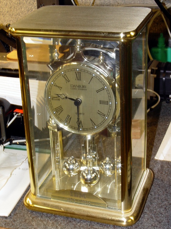
    After 30 years, IBM gave Mary a commemorative clock, after which she promptly retired. Back in the day, they used to hand out Atmos clocks (admittedly, on more momentous occasions), but this isn’t one of those. In fact, although it appears to have a torsion pendulum, that’s a separate motor-driven foo-foo which we immediately turned off:

    Janus Clock - front
    Janus Clock – front

    It normally sits on the living room coffee table (which actually holds a myriad plants next to the front window) where, after we scrapped all the upholstered furniture, the two of us can’t both see the clock face from our chairs. Having a spare clock insert from that repair, we had the same bright idea at the same time: we need a clock with two faces! We came up with Janus independently…

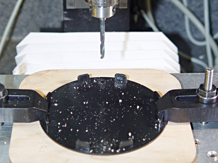
    Despite its fancy appearance, the IBM clock consists mostly of brass and plastic, so I had no qualms about having my way with it in the shop. The new clock insert spanned the clock’s gilt plastic back cover, needing only a #1 drill hole for the adjustment stem, and exactly filled the available space between the back cover and the case. Both movements had enough interior clearance for 3-48 brass screw heads and nuts, so I eyeballed the right spots on the new cover, centered the Sherline spindle on the plate, and drilled two clearance holes 6 mm in from the edges on the vertical diameter:

    Drilling clock insert cover
    Drilling clock insert cover

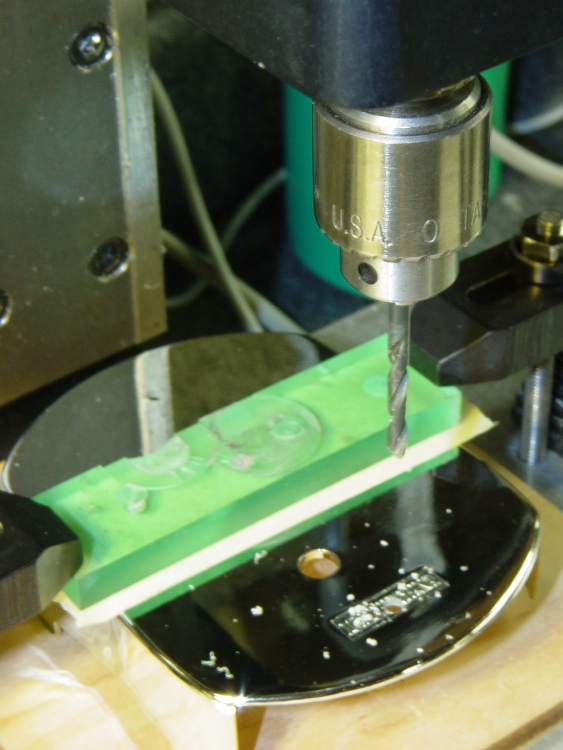
    That put them 61.3 mm apart across the diameter, which would be awkward to duplicate by hand. Manual CNC makes it trivially easy to match-drill holes; I clamped down the gilt back cover from the IBM clock, aligned it to the table, located the center, and drilled two 3-48 clearance holes:

    Drilling torsion clock cover
    Drilling torsion clock cover

    The glow from that polycarbonate packing block isn’t quite so nuclear in real life. The clamping force goes down the side panels of the cover, which had enough of a curve to be perfectly stable. Yes, I’m drilling into air, but came down real slow using the Joggy Thing and it was all good.

    Assemble the two back covers (the holes matched perfectly), mark the adjustment stem hole, disassemble, hand-drill, reassemble, tighten nuts, and install:

    Janus Clock - rear
    Janus Clock – rear

    It does look a bit lumpy from the side, but that’s just because I don’t have any gilding for the black tape wrap:

    Janus Clock - side
    Janus Clock – side

    There, now, that was easy.