The Smell of Molten Projects in the Morning

Ed Nisley's Blog: Shop notes, electronics, firmware, machinery, 3D printing, laser cuttery, and curiosities. Contents: 100% human thinking, 0% AI slop.

Category: Machine Shop

Mechanical widgetry

  • Automated Cookie Cutters: Creating the Height Map Data File

    That process produces a grayscale height map PNG image in the proper orientation:

    Jellyfish - prepared image
    Jellyfish – prepared image

    OpenSCAD, however, requires a flat ASCII data file to build a 3D model, as described there.

    It turns out that a PGM (“Portable Graymap”) file is almost exactly what we need: a fixed format header in ASCII text, followed by the pixel data in either ASCII or binary. To get an ASCII-formatted PGM file from that PNG image:

    convert jellyfish_prep.png -compress None jellyfish.pgm
    

    The top of the PGM file looks like this:

    P2
    149 159
    255
    0 0 0 0 0 0 0 0 0 0 0 0 0 0 0 0 0 0 0 0 0 0 0 0 0 0 0 0 0 0 0 0 0 0 0 0 0 0 0
    0 0 0 0 0 0 0 0 0 0 0 0 0 255 255 255 255 255 255 255 255 255 0 0 0 0 0 0 0 0
    0 0 0 0 0 0 0 0 0 0 0 0 0 0 0 0 0 0 255 255 255 255 255 255 255 255 255 255
    ... more data ...
    

    The data isn’t in the XY array layout that OpenSCAD expects; It Would Be Very Nice If OpenSCAD could read PGM files, including the header describing the array size, but it doesn’t. Fortunately, some Bash-fu can handle the reformatting.

    First, store the number of pixels along the X axis in a Bash variable:

    ImageX=`identify -format '%[fx:w]' ${imagename}_prep.png`
    

    Note the backticks around the whole mess that tell Bash to execute what’s inside and return the value. The -format operation returns the width as an integer, which is what we need.

    Now, returning our attention to the PGM file, convert multiple blanks and line ends to single line ends, thus putting one entry on each output line with no other whitespace:

    cat filename.pgm | tr -s ' \012' '\012'
    

    Nota bene: there’s a leading blank in the first character string and the escape sequences should read “reverse-slash zero one two” to denote the Unix-style line end character (ASCII 10 = newline). I think the meta-markup works around the usual WordPress formatting, but ya never know what can go wrong.

    The first four lines then contain the magic number, X size, Y size, and the maximum data value, respectively:

    P2
    149
    159
    255
    

    Those values are all known, because:

    • The magic number is P2 for ASCII PGM files. It would be useful to verify this, but …
    • The XY values correspond to the image size
    • The maximum data value will be 255 because of  the auto-level operation applied to the image’s 8-bit grayscaleness

    Strip off the first four lines and wrap the remaining data into an array corresponding to the image size:

    tail -n +5 | column -x -c $((8*${ImageX})) > filename.dat
    

    The $((8*${ImageX)) magic comes from the way the column command works: it’s right-aligning each data values in an 8 character column, so you specify the total width of the result in character columns. Think of the parameter as specifying the screen width and you’ll be on the right track.

    That fits neatly into a single line of Bash gibberish:

    cat filename.pgm | tr -s ' \012' '\012' | tail -n +5 | column -x -c $((8*${ImageX})) > filename.dat
    

    The first complete line of that file goes on basically forever, but it actually has the right stuff. You can examine it thusly:

    head -1 filename.dat
    

    The file should then Just Work when sucked into OpenSCAD with the surface() function:

    surface("filename.dat",center=true,convexity=10);
    

    And, indeed, it does:

    Jellyfish - surface model
    Jellyfish – surface model

    Note that it’s oriented with the head in the +Y direction, the tentacles (or whatever) in the -Y direction, and the freckle over the eye on the proper side. Here’s the original PNG image of the cookie for reference:

    Jellyfish - height map image
    Jellyfish – height map image

    Using center=true centers the object on the XY plate, but the base of the solid remains at Z=-1. That makes some sense, as the “solid” part of the model lies below the Z values set by the data: the model includes a one unit thick slab below Z=0 for all points.

    The convexity=10 parameter helps OpenSCAD’s quick rendering code (invoked by hitting F5 in the GUI) determine when it can stop looking for intersections between the visible ray and the object. It doesn’t affect the F6 CGAL compilation & export to STL. Because this routine will eventually be used only from the command line, the value doesn’t matter.

    That works and the height map looks OK, but the model is too large in all directions and the slab below Z=0 has got to go. But it’s looking good…

  • Automated Cookie Cutters: Height Map Image File Preparation

    Having established the OpenSCAD can produce a height map from an input array, a bit more doodling showed how to produce such an array from a grayscale image. I certainly didn’t originate all of this, but an hour or two of searching with the usual keywords produced snippets that, with a bit of programming-as-an-experimental-science tinkering, combine into a useful whole.

    Not being much of an artist, I picked a suitable SVG image from the Open ClipArt Library:

    Jellyfish - color
    Jellyfish – color

    That’s pretty, but we need a grayscale image. Some Inkscape fiddling eliminated all the nice gradients, changed the outline to a dark gray, made all the interior fills a lighter gray, and tweaked the features:

    Jellyfish - gray
    Jellyfish – gray

    Admittedly, it looks rather dour without the big smile, but so it goes. This is still an SVG file, so you have vector-mode lines & areas.

    A bit more work changed the grays to produce different heights, duplicated one of the spots for obvious asymmetry, and exported it as a gritty 160×169 pixel PNG image:

    Jellyfish - height map image
    Jellyfish – height map image

    The low resolution corresponds to a 2 pixel/mm scale factor: 169 pixel = 84.5 mm tall. The cutter wrapped around this image will have a lip that adds about 12 mm, a 1 or 2 mm gap separates the press from the cutter, and there’s a skirt around the whole affair. My Thing-O-Matic build platform measures a scant 120 mm in the Y direction, which puts a real crimp on the proceedings.

    That’s assuming the usual 1 unit = 1 mm conversion factor. If your toolchain regards units as inches, then you need a different scale factor.

    Low resolution also speeds up the OpenSCAD processing; you can use as many pixel/mm as you wish, but remember that the extruded filament is maybe 0.5 mm wide, so anything beyond 4 pixel/mm might not matter, even if the motion control could benefit from the smoother sides. Features down near the resolution limit of the model may produce unusual effects for thin walls near the thread width, due to interpolation & suchlike (which is why I got rid of the smile). The processing time varies roughly with the number of pixels, so twice the resolution means four times more thumb-twiddling.

    Caveats:

    • You’re looking at a cookie lying on a table: this is the top view
    • Background surrounding the image should be full white = 255
    • Highest points should be very light gray, not full white, to avoid creating islands
    • Lowest points may be black; I use a very dark gray
    • No need for an outline
    • Smooth gradients are OK, although they’ll become harshly quantized by the layer thickness
    • You can probably use JPG instead of PNG, but these aren’t big files
    • Remember this is a cookie press, not a work of art

    With a suitable PNG image file in hand, use ImageMagick to prepare the image:

    • Crop to just the interesting part: -trim (depends on the four corners having background color)
    • Convert the image to grayscale: -type Grayscale (in case it’s a color image)
    • Make it 8 bit/pixel: -depth 8 (more won’t be helpful)
    • Stretch the contrast: -auto-level (to normalize the grayscale to the full range = full height)
    • Reverse left-to-right to make a cookie press: -flop (think about it)
    • Invert the grayscale to make the cookie press surface: -negate (again, think about it)
    • Reverse top-to-bottom to correct for upcoming OpenSCAD surface() reversal: -flip

    Thusly:

    convert filename.png -trim -type Grayscale -depth 8 -auto-level -flop -negate -flip filename_prep.png
    

    Which produces this image:

    Jellyfish - prepared image
    Jellyfish – prepared image

    Combining -flop and -flip just rotates the image 180° around its center, but I can’t help but believe transposing the bits works out better & faster than actually rotating the array & interpolating the result back to a grid. On the other paw, if there isn’t a special case for (multiples of) right-angle rotation(s), there should be. [grin]

    The prepared image is 149×159, because the -trim operation removed the surrounding whitespace. You can do that manually, of course, keeping in mind that the corners must be full white to identify the background.

    Next: convert that image to a data array suitable for OpenSCAD’s surface() function…

  • Automated Cookie Cutters: OpenSCAD surface() Function

    While pondering the notion of making cookie cutters, it occurred to me that the process could be automated: a grayscale height map image of the cookie should be enough to define the geometry. The existing height map solutions (like William Adams’s fine work) seem entirely too heavyweight, what with custom Windows or Java programs and suchlike. Some doodling indicates that a simpler solution may suffice for my simple needs, although the devil always hides in the details.

    The overall problem with a cookie press involves producing a non-rectangular solid with a bumpy upper surface corresponding to the grayscale values of an image: dark pixels = low points of the surface, light pixels = peaks. The image size controls the XY extent of the solid and the pixel values control the Z, with some known value (likely either black or white) acting as a mask around the perimeter. Given such a solid, you can then wrap a cutter blade and handle around the outline, much as I did for the Tux cutter.

    OpenSCAD has a lightly documented surface() function that reads an ASCII text file consisting of an array of numeric values. Each array element defines a 1 × 1 unit square of the resulting 3D object; the example in the doc shows a 10 x 10 array producing a 10 x 10 unit object. Each numeric value sets the height of the surface at the center of the square.

    This array, slightly modified from the one in the doc, shows how that works:

    9 9 8 7 6 5 5 5 5 1
    9 9 7 6 6 4 3 2 1 0
    8 7 6 6 4 3 2 1 0 0
    7 6 6 4 3 2 1 0 0 0
    6 6 4 3 2 1 1 0 0 0
    6 6 3 2 1 1 1 0 0 0
    6 6 2 1 1 1 9 9 9 0
    6 6 1 0 0 0 9 8 9 0
    3 1 0 0 0 0 9 9 9 0
    9 8 7 6 5 4 3 2 1 0
    

    Feeding that into this OpenSCAD program:

    module ShowPegGrid(Space = 10.0,Size = 1.0) {
    
      Range = floor(50 / Space);
    
    	for (x=[-Range:Range])
    	  for (y=[-Range:Range])
    		translate([x*Space,y*Space,Size/2])
    		  %cube(Size,center=true);
    
    }
    
    ShowPegGrid();
    surface("/tmp/test.dat",center=true,convexity=10);
    

    Produces this object, surrounded by a few non-printing 1 unit alignment cubes on the Z=0 plane for scale:

    Example Object
    Example Object

    Some things to note:

    • The text array looks like it builds downward from the upper left, but the solid model builds from the origin toward the +X and +Y directions, with the first line of the array appearing along Y=0. This reverses the object along the Y axis: the first line of the array is the front side of the object.
    • The “center=true” option centers the object in XY around the Z axis, with a 1 unit thick slab below the entire array; the top surface of that slab (at Z=0) represents the level corresponding to 0 elements in the array.
    • Each array element becomes a square one unit on a side; the RepRap software chain regards units as millimeters
    • The center point of each element’s square is at the nominal height
    • The Z coordinate of the edges of those squares linearly interpolate between adjacent centers
    • Vertical edges become slanted triangular facets

    Remember that STL files contain a triangular tessellation (or whatever you call it in 3D) of the object surface, which means rectangles aren’t natural. The edge interpolation make the whole thing work, because an array of pure square pillars probably won’t be a 2-manifold object: some pillars would share only a common vertical edge. The interpolation does, however, produce a bazillion facets atop the object.

    So the problem reduces to generating such an array from a grayscale image, for which some ImageMagick and Bash-fu should suffice, and then manipulating it into a model that will produce a cookie press and cutter. More on that tomorrow…

    [Update: image file, height map file, solid modeling, printing]

  • Whirlpool Refrigerator: Replacement Freezer Shelf Bracket

    Somehow, one of the brackets that supports the small shelf inside the freezer of our Whirlpool refrigerator went missing over the many intervening years and repairs; we never used that shelf and stashed it in a closet almost immediately after getting the refrigerator, so not having the bracket didn’t matter. We recently set up a chest freezer in the basement for all the garden veggies that used to fill all the space available and decided to (re-)install the shelf, which meant we needed a bracket.

    It’s impossible to figure out exactly which “shelf stud” in that list would solve the problem, but one of the upper-left pair in that set seems to be about right. On the other paw, I don’t need all the other brackets and doodads and screws, sooo… I can probably make one.

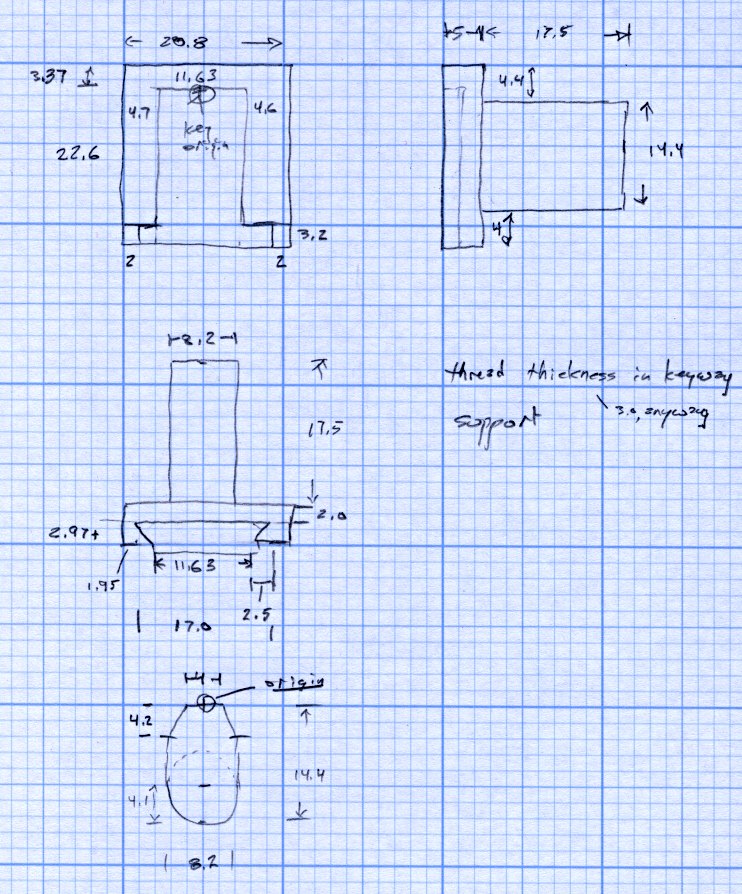
    Start with a few measurements, then doodle up the general idea:

    Refrigerator Bracket - dimension doodle
    Refrigerator Bracket – dimension doodlet’s time to conjure up a solid model:

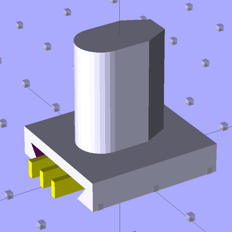
    A bit of OpenSCAD solid modeling:

    Refrigerator Bracket Pin - solid model
    Refrigerator Bracket Pin – solid model

    The yellow bars support the ceiling of that big dovetail, which would otherwise sag badly. The OEM bracket has nicely rounded corners on the base and a bit of an overall radius at the end of the post; this was pretty close and easier to do.

    Now it’s time to Fire the Thing-O-Matic…

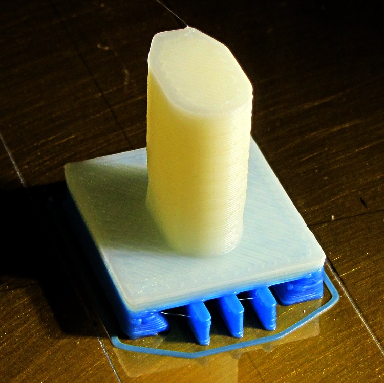
    I switched from blue to white filament during the print, because I figured I’d print another one after I got the sizes right, so it emerged with an attractive blue base:

    Bracket on build platform
    Bracket on build platform

    A better view of the support structure:

    Bracket - dovetail support structure
    Bracket – dovetail support structure

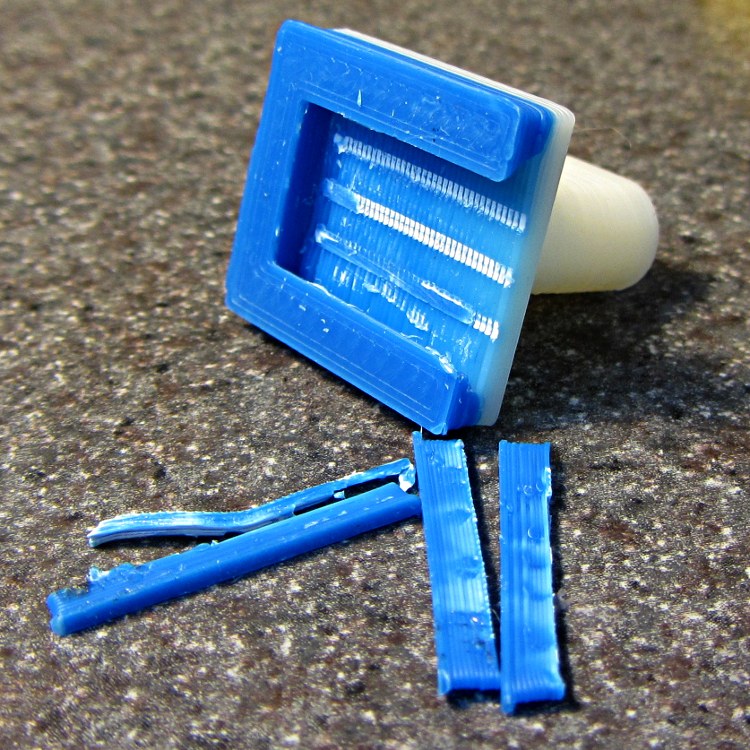
    Two of the bars snapped off cleanly, but the third required a bit of scraping:

    Bracket - support scars
    Bracket – support scars

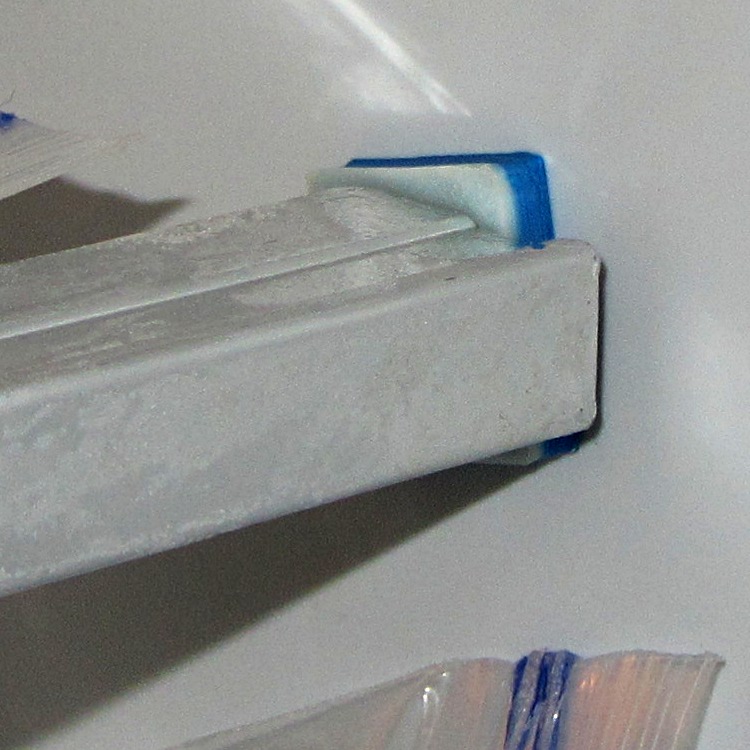
    Somewhat to my surprise, Prototype 001 slipped snugly over the matching dovetail on the freezer wall, with about the same firm fit as the OEM brackets:

    Refrigerator bracket - installed
    Refrigerator bracket – installed

    And it works perfectly, apart from that attractive blue base that I suppose we’ll get used to after a while:

    Refrigerator bracket - in use
    Refrigerator bracket – in use

    I have no idea whether ABS is freezer-rated. It seems strong enough and hasn’t broken yet, so we’ll declare victory and keep the source code on tap.

    The whole project represents about an hour of hammering out OpenSCAD code for the solid model and another hour of printing, which means I’d be better off to just buy the parts kit and throw away the unused bits. Right?

    I loves me my Thing-O-Matic…

    The OpenSCAD source code:

    // Shelf support bracket
    // for Whirlpool freezer
    // Ed Nisley KE4ZNU Octoboer 2012
    
    //include </mnt/bulkdata/Project Files/Thing-O-Matic/MCAD/units.scad>
    //include </mnt/bulkdata/Project Files/Thing-O-Matic/Useful Sizes.scad>
    
    // Layout options
    
    Layout = "Build";
     // Overall layout: Show Build
     // Printing plates: Build
     // Parts: Post Base Keystone Support
    
    ShowGap = 10; // spacing between parts in Show layout
    
    //- Extrusion parameters must match reality!
    // Print with +1 shells and 3 solid layers
    
    ThreadThick = 0.25;
    ThreadWidth = 2.0 * ThreadThick;
    
    HoleWindage = 0.2;
    
    function IntegerMultiple(Size,Unit) = Unit * ceil(Size / Unit);
    
    Protrusion = 0.1; // make holes end cleanly
    
    //----------------------
    // Dimensions
    
    PostLength = 17.5;
    PostWidth = 8.2;
    PostHeight = 14.4;
    PostOffset = 4.4;
    
    PostTopWidth = 4.0;
    PostTopHeight = 4.2;
    
    BaseLength = 22.6;
    BaseWidth = 20.8;
    BaseThick = 5.0;
    
    KeystoneOffset = 3.4;
    KeyThick = IntegerMultiple(3.0,ThreadThick);
    KeyBase = 2.5;
    SlotOpening = 11.63;
    //----------------------
    // Useful routines
    
    module PolyCyl(Dia,Height,ForceSides=0) { // based on nophead's polyholes
    
    Sides = (ForceSides != 0) ? ForceSides : (ceil(Dia) + 2);
    
    FixDia = Dia / cos(180/Sides);
    
    cylinder(r=(FixDia + HoleWindage)/2,
     h=Height,
     $fn=Sides);
    }
    
    module ShowPegGrid(Space = 10.0,Size = 1.0) {
    
     Range = floor(50 / Space);
    
     for (x=[-Range:Range])
     for (y=[-Range:Range])
     translate([x*Space,y*Space,Size/2])
     %cube(Size,center=true);
    
    }
    
    //-------------------
    // Component parts
    
    //--- Post
    
    module Post(h=PostLength) {
    
    PostTopAngle = atan((PostWidth - PostTopWidth)/(2*PostTopHeight));
    PostBottomRadius = PostWidth/2;
    
    PostPolyTop = [PostTopWidth/2,0];
    PostPolyBottom = [PostWidth/2,-PostTopHeight];
    
    hull() {
     linear_extrude(height=h) {
     polygon(points=[
     [-PostPolyTop[0],PostPolyTop[1]],
     PostPolyTop,
     PostPolyBottom,
     [-PostPolyBottom[0],PostPolyBottom[1]]
     ]);
     translate([0,-PostHeight + PostBottomRadius])
     circle(r=PostBottomRadius,$fn=4*8);
     }
     }
    }
    
    //--- Base block
    
    module Base() {
    
     linear_extrude(height=BaseThick)
     square([BaseWidth,BaseLength],center=true);
    
    }
    
    //-- Keystone slot
    
    module Keystone() {
    
    Tx = SlotOpening/2 + KeyBase;
    
     rotate([90,0,0])
     linear_extrude(height=BaseLength)
     polygon(points=[
     [-Tx,KeyThick],
     [ Tx,KeyThick],
     [ SlotOpening/2,0],
     [ SlotOpening/2,-Protrusion],
     [-SlotOpening/2,-Protrusion],
     [-SlotOpening/2,0]
     ]);
    }
    
    //--- Support structure
    
    module Support() {
    
    SupportLength = BaseLength - 2*ThreadWidth;
    SupportWidth = 2*ThreadWidth;
    SupportHeight = KeyThick - Protrusion;
    
    SupportPeriod = 7.0*ThreadWidth;
    
    SupportBeams = 3; // must be odd -- choose to fit
    SIndex = floor((SupportBeams - 1)/2);
    
    for (i=[-SIndex:SIndex])
     translate([(i*SupportPeriod - SupportWidth/2),-(SupportLength + ThreadWidth),0])
     color("Yellow") cube([SupportWidth,SupportLength,SupportHeight]);
    }
    
    //--- The whole thing!
    
    module Bracket(ShowSupp) {
    
     union() {
     difference() {
     Base();
     translate([0,(BaseLength/2 - KeystoneOffset),0])
     Keystone();
     }
     translate([0,(BaseLength/2 - PostOffset),BaseThick - Protrusion])
     Post(h=(PostLength + Protrusion));
     }
    
     if (ShowSupp)
     translate([0,(BaseLength/2 - KeystoneOffset),0])
     Support();
    
    }
    
    //----------------------
    // Build it!
    
    ShowPegGrid();
    
    if (Layout == "Show")
     Bracket(false);
    
    if (Layout == "Build")
     Bracket(true);
    
    if (Layout == "Post")
     Post();
    
    if (Layout == "Base")
     Base();
    
    if (Layout == "Keystone")
     Keystone();
    
    if (Layout == "Support") {
     Support();
    % Keystone();
    }
    
  • Recommended Tool: Bosch GLR225 Laser Rangefinder

    I’ve been doing some amateur surveying in preparation for the long-awaited driveway paving project, just to see where the property boundaries might be, and this Bosch GLR225 laser rangefinder makes it wonderfully easy to measure distances:

    Bosch GLR225 Laser Rangefinder
    Bosch GLR225 Laser Rangefinder

    It’s good up to 230 feet = 70 meters, which means you can measure a sizable chunk of property in one shot. It reads down to 2 inches with 1/16 inch accuracy / resolution (call it 50 mm and 1.5 mm), so one could use it for setups in the shop. It can solve right triangles, which means you can measure distances with an obstruction in the middle, and has a few other tricks. Other rangefinders evidently have more tricks, but I favor writing direct measurements on paper and making computations based those values, rather than using mysterious results direct from the field that can’t be easily verified at the desk.

    I tried measuring the nominal 212 foot distance to the Hudson River from the center of the Walkway, but it reported an error. Most likely, specular reflections from water don’t work well, at least not at that distance.

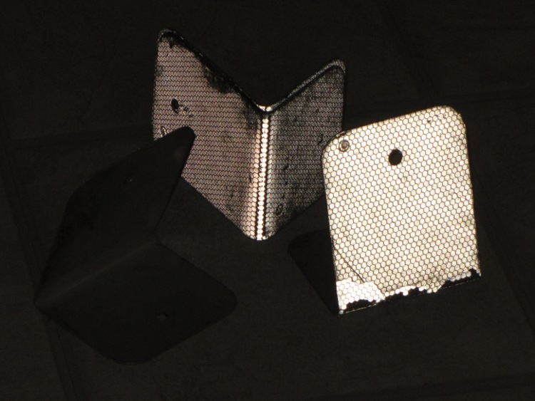
    You can buy retroreflective targets, but the Basement Laboratory Warehouse Wing disgorged what looks like roadside border markers, pre-bent into a useful shape:

    Laser targets - normal
    Laser targets – normal

    Seen by reflected light, they’re much more impressive:

    Laser targets - flash
    Laser targets – flash

    They came with the house, so I don’t know their provenance. What I do know is that I can’t hold the rangefinder steady enough to keep the spot on the target at much more than 100 feet. If I get around to doing much more surveying, I must conjure up a tripod mount; the base has a 1/4-20 socket in an awkward location and can measure relative to the screw centerline. Perhaps a rifle stock with a spotting scope would be handy, too, although I’d certainly acquire another black spot on my record.

    If you were going to use it in the shop, you’d want a rotating pivot aligned at the intersection of the tripod socket and sensor port to get a known center point.

    You can get one on eBay at a substantial discount, of course…

  • Inkjet Colors vs. Time

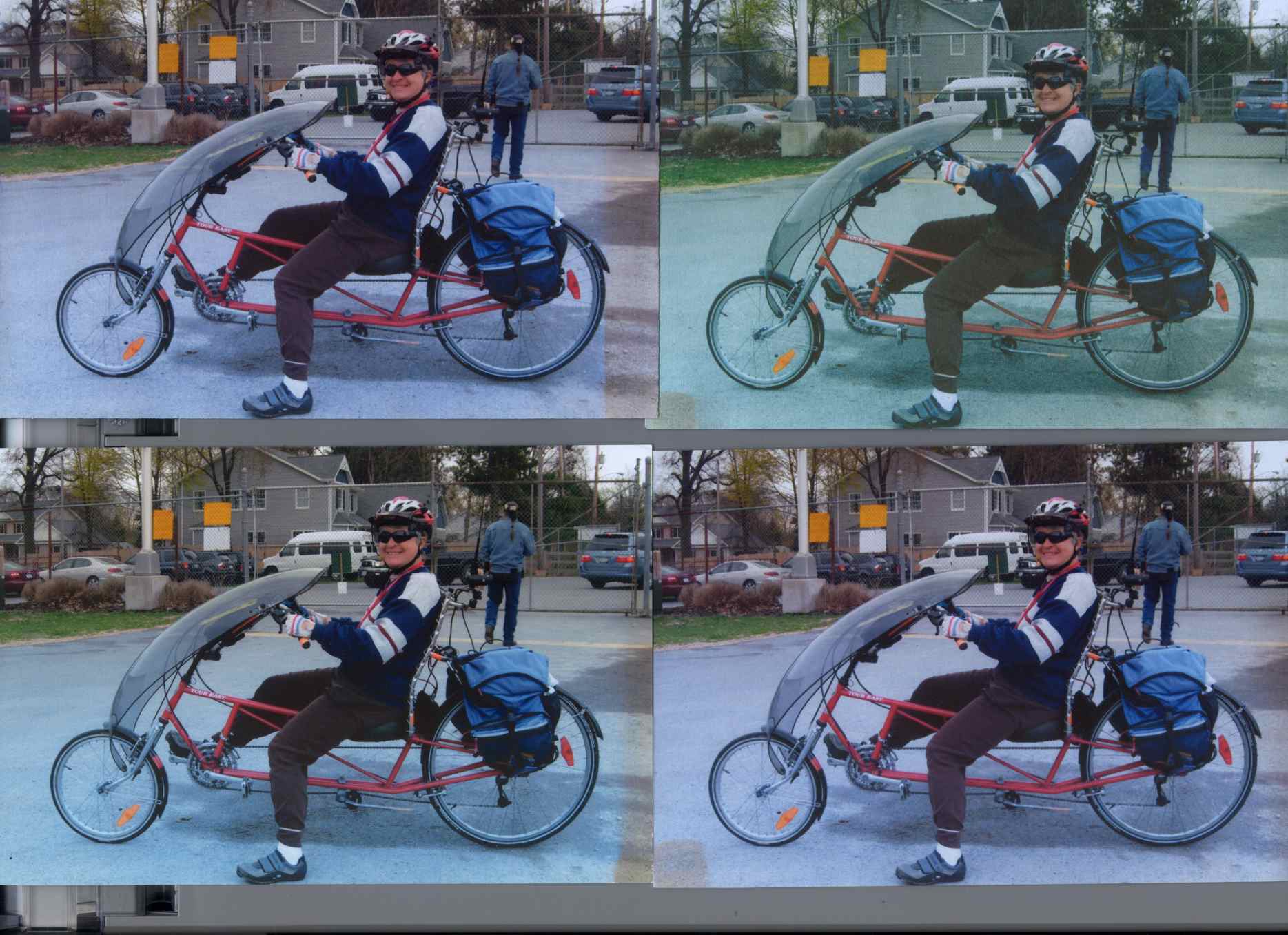
    Back in December 2007 I printed four copies of a picture on various papers with the Canon S630 and hung them on a floor joist over my workbench, directly below a fluorescent shop light. Having just hung those screwdrivers where the pictures used to be, it’s time to see what’s happened.

    The pictures, scanned on an HP C7670A (aka Scanjet 6300C) against the neutral gray of the ADF platen:

    Inkjet Colors vs. Paper vs. Time
    Inkjet Colors vs. Paper vs. Time

    The papers, clockwise from lower left:

    • Glossy
    • Matte
    • Plain
    • Inkjet

    While the scanner isn’t renown for its color fidelity, the overall results look about right; the platen really is that shade of gray and the upper-right picture has a sickly green hue.

    The faded edges along the right side of the left-hand image show where the adjacent sheet overlapped: the colors didn’t fade nearly as much. The small rectangles on the lower left corners of the right-hand images show where I put clothes pins to keep the sheets from curling.

    All of the images have a blue overtone; the magenta dye fades out with exposure to UV from the fluorescent fixture.

    As you’d expect, the glossy paper looks best, with very crisp detail. The inkjet paper is next, followed by the matte, and the plain paper in the upper right obviously doesn’t support the ink well at all.

    Of course, after five years I no longer have any of those papers and am using entirely different ink…

    To show that the scanner really does matter, here’s the same set of images from a Canon LiDE 30:

    Inkjet Colors - Canon LiDE30
    Inkjet Colors – Canon LiDE30

    In both cases. that’s without any color correction / gamma compensation / whatever. I should fish out my scanner calibration targets and go through the whole color calibration dance again; with any luck, the Linux color management infrastructure will be less inadequate by now.

    IIRC, we were doing public safety radio at an event at the Dutchess County Fairgrounds with the Mt Beacon Amateur Radio Club. This was before the Diamond antenna mounts disintegrated, too.

    Memo to Self: If you love it, don’t expose it to UV.

  • Longboard Electronics Case: Now With Mouse Ears

    Our Larval Engineer may have a commission to fit her Speed-Sensing Ground Effect Lighting controller to another longboard. To that end, the case now sports mouse ears to spread the force from the cooling ABS over more of the Kapton tape, in the hope the plastic won’t pull the tape off the aluminum build platform:

    Longboard Case Solid Model - mouse ears
    Longboard Case Solid Model – mouse ears

    That view shows the bottom slice that will hold the battery, but the ears appear on all three layers.

    The OpenSCAD source code is now up on Github, which should make it easier to update & share.