Ed Nisley's Blog: Shop notes, electronics, firmware, machinery, 3D printing, laser cuttery, and curiosities. Contents: 100% human thinking, 0% AI slop.
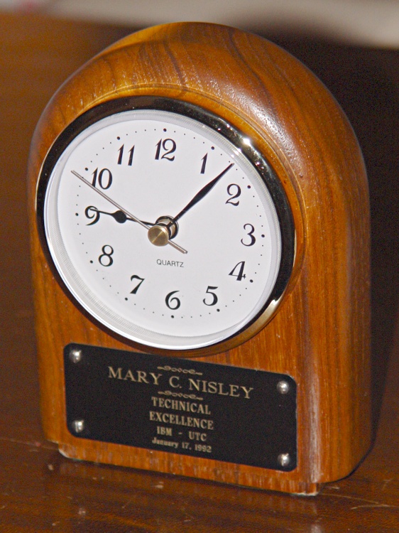
The double-stick foam tape holding the plate on the front aged out a few years later, at which point I cleaned off the solidified goo, drilled 2-56 clearance holes in the plate and tapping holes in the clock base, installed four pan head stainless screws, and neatly aligned the slots. That’s what it should have looked like from the beginning; this was, after all, a Technical award…
The clock movement failed recently and I got a drop-in clock insert from Klockit to put it back in operation. The fit wasn’t quite solid, but two wraps of silicone tape around the case under the ribbed friction-fit band solved that problem.
One new movement cost just about as much as the shipping, so I bought a pair with black and white faces. Mary picked the white face for this clock, which left the black movement as a spare.
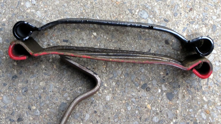
It’s leaf-shredding season again and our MTD Chipper-Shredder began shredding not nearly as well as it had in years gone by. Last season I laid in a stock of replacement parts, so I swapped in a new Shredder Screen (781-0457):
MTD Chipper-Shredder screen
The flail blades (719-0329) on the massive rotating impeller assembly protrude through the parallel openings in the screen, which is where most of the shredding action happens. The old red screen bent outward enough so that the blades pushed the leaves against the screen, rather than through it, producing frequent clogs.
Now it works fine again… although I’ve had just about as much fun shredding leaves as any one person should experience in one month.
The Vassar Farm Garden requires fairly heavy watering, because it’s in full sun all day long, so we lay in a set of drip lines connected through Y valves to a main feeder line running down one end of the plot. Plastic valves tend to be overly fragile, so this year I tried a few much larger full-flow ball valves with a metallic housing:
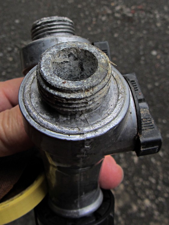
Corroded Garden Y Valve
This valve lay on the ground (as they all do) just inside the gate and served as an occasional supply for a short hose with the hand sprinkler head. I don’t know what’s driving this corrosion, but it’s eating the external threads as well as the valve bore.
Those failures came from two separate cable snags that stalled the X and Y stepper motors for about 1 mm of travel. Fortunately, I wasn’t paying attention and, by the time I figured this out, the thing was nearly built, so I let it run to completion. The thick base plate accounts for most of the plastic, anyway.
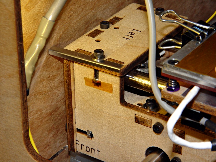
First, the cable bundle on the right snagged on the socket-head cap screw just in front of the X axis limit switch (hidden behind the bundle here). This picture, taken after the +12 V pin in the HBP connector burned through, shows the typical snarl of wires inside a Thing-O-Matic:
Thing-O-Matic – HBP cable routing
The rewired thermistor cable snagged on the bulldog clip holding the top aluminum plate. This picture, taken after the thermistor pads fell off the HBP, shows the filler plate I put in place to prevent the cable (entering from the top and passing below the white cable on the HBP) from jamming in the gap between the Y axis stage and the case, but you can see how the bulldog clip handle could snag it when the platform moves rearward from the front left corner (+X +Y):
HBP Thermistor cable – snag shield and bulldog clamp
The fat gray cable flat against the case in that picture carries the X axis stepper drive signals up-and-over the Y axis. The thinner gray thermistor cable emerges from the electronics bay inside the case corner, then arches in from thetop.
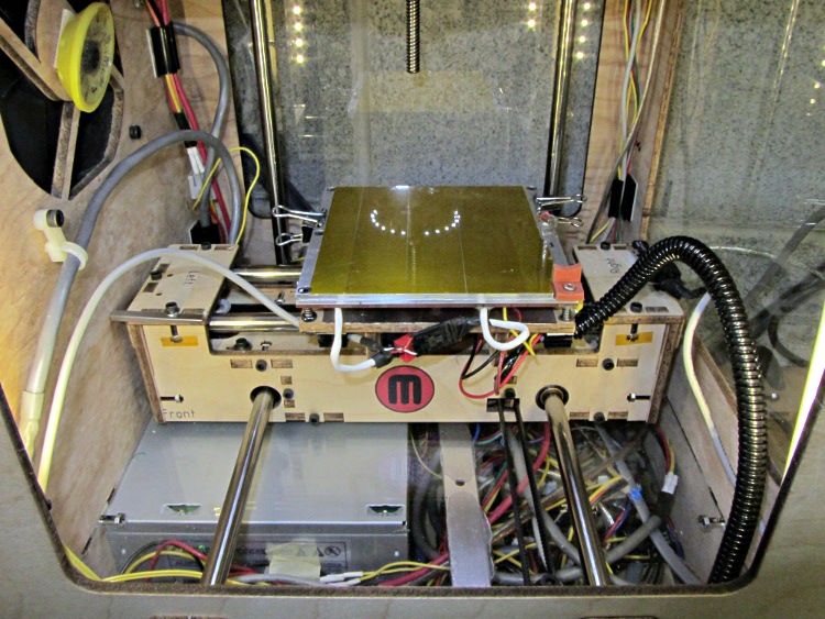
My buddy Aitch recently gave me a few meters of corrugated wire loom, so I moved the bulldog clip rearward and bundled all those loose HBP wires in one tidy snood:
Thing-O-Matic – X axis cable loom
I’m sure something else will go wrong, but the machinery looks marginally less haphazard and the cables don’t snag while I’m watching…
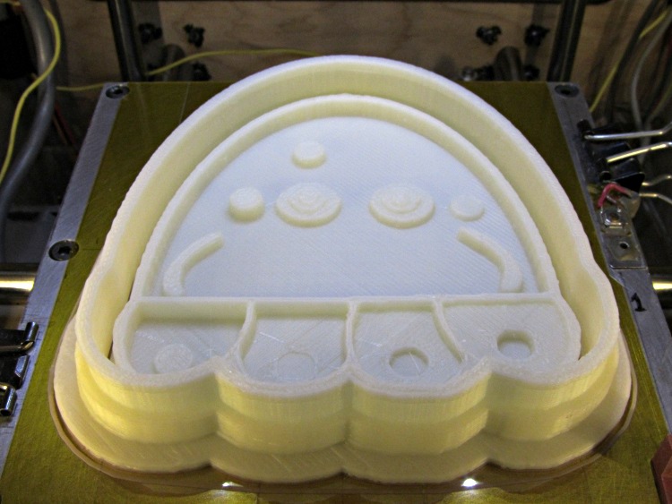
They’re a bit more impressive on the build platform, where the skirt thread around the perimeter extends slightly beyond the usual 100 mm width limit into the no-go zone behind the nozzle wiper. The bizarre lighting from the warm-white front LEDs and the cool-white overhead LED ring emphasizes the 3D features:
Jellyfish Cookie Cutter – on build platform
Somewhat to my surprise, the gritty nature of the bitmap source image didn’t cause a problem. The perimeters consist of many tiny segments, but most of the time goes to filling the interior (20% density, square pattern) and covering the flat surfaces, so the whole thing chugs along at a pretty good pace. Overall, it took something over an hour.
So, given a height-map grayscale image:
Manually tweaked jellyfish-high.png
I (and you!) can automatically create the solid model of a matched cookie cutter and press:
jellyfish-high – Cutter and Press – top view
And then we can produce as many chunks of plastic as needed for our baking session!
Printing that huge block of plastic did, however, uncover two longstanding mechanical problems. More tomorrow…
As expected, my crude bearing repairs on our Whirlpool refrigerator’s freezer fan didn’t last forever; the freezer dog crept back inside over the course of a few months. I recently ordered another replacement fan (yes, sixty bucks for an open-frame fan!), installed it, and have some interesting data points.
The OEM fan in the Whirlpool refrigerator was made by FSP and has no country of origin. The date code on the winding insulation reports 1993 and it lasted for the better part of a dozen years.
The replacement fan, which never sounded quite right and failed in short order, was made by Exact Replacement Parts and has no country of origin. I scrawled 2006 on it, although the bearing noise caused me to remove it almost immediately and re-fix the OEM fan bearings.
The new fan is once again made by FSP, comes with Whirlpool logos on the screw-and-bushing kit bag, and sports Made In Mexico on the winding insulation. So far, it’s sounded OK, although the normal fan whir seems a bit louder & growlier than before. No howls, though, and that counts for a lot.
I infer that the ERP fans weren’t entirely satisfactory, but that’s just a guess.
I assume you’ll pick a workable dots/mm resolution and suchlike for your setup, so they’re hardcoded into the script. You could add them to the command line if you like.
Starting from the same jellyfish.svg file as before, I came up with a slightly different jellyfish-high.png grayscale height map image with more dots (246×260 dots at 3 dot/mm = 82×87 mm). The original 160×169 file required about half an hour to render and, as you’d expect, increasing the number of dots by 1.5 (nearly √2) doubled the time to just over an hour:
Manually tweaked jellyfish-high.png
The first convert step turns that into the basic height map jellyfish_prep.png file:
jellyfish-high_prep.png
The next two convert steps produce two ASCII PGM files:
jellyfish-high_map.pgm
jellyfish-high_plate.pgm
The _map file has the grayscale height map data, which is identical to the prepared PNG image:
jellyfish-high_map
The _plate file defines the outline of the cookie cutter with a completely white interior, which is why the original cookie height map image can’t contain any pure white areas inside the outline (they’d become black here and produce islands). It seems the OpenSCAD minkowski() function runs significantly faster when it doesn’t process a whole bunch of surface detail; all we care about is the outline, so that’s all it gets:
jellyfish-high_plate
I originally composited the height maps on a known-size platen and worked with those dimensions, but it’s easier to just extract the actual image dimensions and feed them into the code as needed. As with all ImageMagick programs, identify has a myriad options.
Those two lines of Bash gibberish reformat the ASCII PGM files into the ASCII DAT arrays required by OpenSCAD’s surface() function.
The MakeSurface.scad script eats a DAT height map file and spits out a corresponding STL file. The Height parameter defines the overall Z-axis size of the slab; the maximum 255 corresponds to pure white in the image file:
// Generate object from image height map
// Ed Nisley - KE4ZNU
// October 2012
// This leaves the rectangular slab below Z=0 over the full image area
//		... reduced in thickness by the Height/255 ratio

FileName = "noname.dat";				// override with -D FileName="whatever.dat"
Height = 255;						// overrride with -D Height=number
DotsPerMM = 2;						// overrride with -D DotsPerMM=number

ScaleXYZ = [1/DotsPerMM,1/DotsPerMM,Height/255];

echo("File: ",FileName);
echo("Height: ",Height);
echo("Dots/mm: ",DotsPerMM);
echo("Scale: ",ScaleXYZ);

module ShowPegGrid(Space = 10.0,Size = 1.0) {
  Range = floor(50 / Space);
	for (x=[-Range:Range])
	  for (y=[-Range:Range])
		translate([x*Space,y*Space,Size/2])
		  %cube(Size,center=true);
}

//- Build it

ShowPegGrid();

scale(ScaleXYZ)
	surface(FileName,center=true,convexity=10);
The grid defining the build platform doesn’t show up in the output file; it’s there just for manual fiddling inside the GUI. When run from the command line, OpenSCAD simply creates the output file.
The _map.stl file has the height map data that will form the cookie press:
jellyfish-high_map – Model
The _plate.stl file is basically a digital bar cookie that will define the cutter:
jellyfish-high_plate – Model
It’s possible to produce the cutter in one shot, starting from the DAT files, but having the two STL files makes it (barely) feasible to experiment interactively within the OpenSCAD GUI.
This OpenSCAD program produces the cutter and press:
// Cookie cutter from grayscale height map using Minkowski sum
// Ed Nisley KE4ZNU - November 2012

//-----------------
// Cookie cutter files

BuildPress = true;
BuildCutter = true;

fnPress = "nofile.stl";					// override with -D 'fnPress="whatever.stl"'
fnPlate = "nofile.stl";					// override with -D 'fnPlate="whatever.stl"'

ImageX = 10;						// overrride with -D ImageX=whatever
ImageY = 10;

MaxConvexity = 5;					// used for F5 previews in OpenSCAD GUI

echo("Press File: ",fnPress);
echo("Plate File: ",fnPlate);
echo("Image X: ",ImageX," Y: ",ImageY);

//- Extrusion parameters - must match reality!

ThreadThick = 0.25;
ThreadWidth = 2.0 * ThreadThick;

//- Cookie cutter parameters

TipHeight = IntegerMultiple(8,ThreadThick);		// cutting edge
TipWidth = 4*ThreadWidth;

WallHeight = IntegerMultiple(7,ThreadThick);		// center section
WallWidth = 8*ThreadWidth;

LipHeight = IntegerMultiple(2.0,ThreadThick);		// cutter handle
LipWidth = IntegerMultiple(8.0,ThreadWidth);

CutterGap = IntegerMultiple(2.0,ThreadWidth);		// gap between cutter and press

PlateThick = IntegerMultiple(3.0,ThreadThick);		// solid plate under press relief

//- Build platform

PlatenX = 100;						// build platform size
PlatenY = 120;
PlatenZ = 120;						// max height for any object
PlatenFuzz = 2;

MaxSize = max(PlatenX,PlatenY);				// larger than any possible dimension ...

ZFuzz = 0.20;						// height of numeric junk left by grayscale conversion
ZCut = 1.20;						// thickness of block below Z=0

//- Useful info

function IntegerMultiple(Size,Unit) = Unit * ceil(Size / Unit);

Protrusion = 0.1;					// make holes and unions work correctly

//-----------------
// Import height map STL, convert to cookie press image

module PressSurface() {

	translate([0,0,-ZFuzz])
		difference() {
			import(fnPress,convexity=MaxConvexity);
			translate([-(ImageX + PlatenFuzz)/2,-(ImageY + PlatenFuzz)/2,-ZCut])
				cube([(ImageX + PlatenFuzz),(ImageY + PlatenFuzz),ZCut+ZFuzz],center=false);
		}
}

//-----------------
// Import plate STL, slice off a slab to define outline

module Slab(Thick=1.0) {
	intersection() {
		translate([0,0,Thick/2])
			cube([(PlatenX+PlatenFuzz),(PlatenY+PlatenFuzz),Thick],center=true);
		translate([0,0,-1])
			import(fnPlate,convexity=MaxConvexity);
	}
}

//- Put peg grid on build surface

module ShowPegGrid(Space = 10.0,Size = 1.0) {

  Range = floor(50 / Space);

	for (x=[-Range:Range])
	  for (y=[-Range:Range])
		translate([x*Space,y*Space,Size/2])
		  %cube(Size,center=true);

}

//- Build it

ShowPegGrid();

if (BuildPress) {
	echo("Building press");
	union() {
		minkowski() {					// fingernail ridge around press
			Slab(LipHeight - 1);			//  ... same thickness as cutter lip
			cylinder(r=CutterGap/2,h=1);
		}
		translate([0,0,(LipHeight - Protrusion)])	// solid plate under press
			Slab(PlateThick - LipHeight + Protrusion);
		translate([0,0,PlateThick])			// cookie press height map
			intersection() {
				import(fnPress,convexity=MaxConvexity);
				translate([0,0,-Protrusion])
					Slab(PlatenZ + Protrusion);
			}

	}
}

if (BuildCutter) {
	echo("Building cutter");
	difference() {
		union() {					// stack cutter layers
			translate([0,0,(WallHeight + LipHeight - 1)])
				minkowski() {
					Slab(TipHeight - 1);
					cylinder(r=(TipWidth + CutterGap),h=1);
				}
			translate([0,0,LipHeight - 1])
				minkowski() {
					Slab(WallHeight - 1);
					cylinder(r=(WallWidth + CutterGap),h=1);
				}
			minkowski() {
				Slab(LipHeight - 1);
				cylinder(r=(LipWidth + CutterGap),h=1);
			}
		}
		minkowski() {					// punch out opening for cookie press
			translate([0,0,-2])
				Slab(PlatenZ);
			cylinder(r=CutterGap,h=1);
		}
	}
}
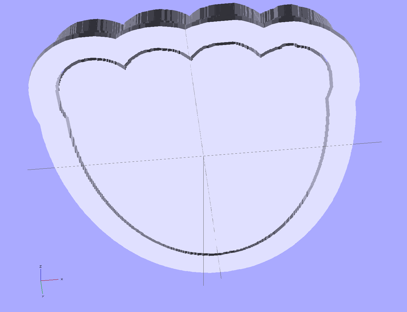
The top view shows the height map press nested inside the cutter blade, but it’s not obvious they’re two separate pieces:
jellyfish-high – Cutter and Press – top view
The bottom view shows the 1 mm gap between the two objects:
jellyfish-high – Cutter and Press – bottom view
Now, to print the thing [Update:like that] so I can make some cookies…
Further musings:
Printing separately would allow a tighter fit between the press and the cutter: an exact fit won’t work, but 2 mm may be too much.
A knob glued on the flat surface of the press would be nice; the fingernail ridge may get annoying.
PLA seems more socially acceptable than ABS for foodie projects. Frankly, I doubt that it matters, at least in this application.