Ed Nisley's Blog: Shop notes, electronics, firmware, machinery, 3D printing, laser cuttery, and curiosities. Contents: 100% human thinking, 0% AI slop.
The horrible paint crazing came from “priming” the bare plywood scrap (yes, that’s a stray hole from its previous life) with a specialty white paint intended for plastic lawn furniture; it apparently gets along poorly with the forget-me-not fluorescent red topcoat. Doesn’t matter in this application and uses up more of both rattlecans, so it’s all good.
Of course, after tucking it in the bike’s underseat bag, I spotted the lost plate along the DCRT: now I have a spare!
The cutter is still attached to the raft that, it seems, is required for passable results on the Afinia’s platform.
Having already figured out how to wrap a cutter around a shape, the most straightforward procedure starts by extracting the cutter’s shape. So, lay the cutter face down on the scanner and pull an image into GIMP:
Afinia Robot – scan
Blow out the contrast to eliminate the background clutter, then posterize to eliminate shadings:
Afinia Robot – scan enhanced
Select the black interior region, grow the selection by a pixel or two, then shrink it back to eliminate (most of) the edge granularity, plunk it into a new image, and fill with black:
Afinia Robot – scan filled
Now the magic happens…
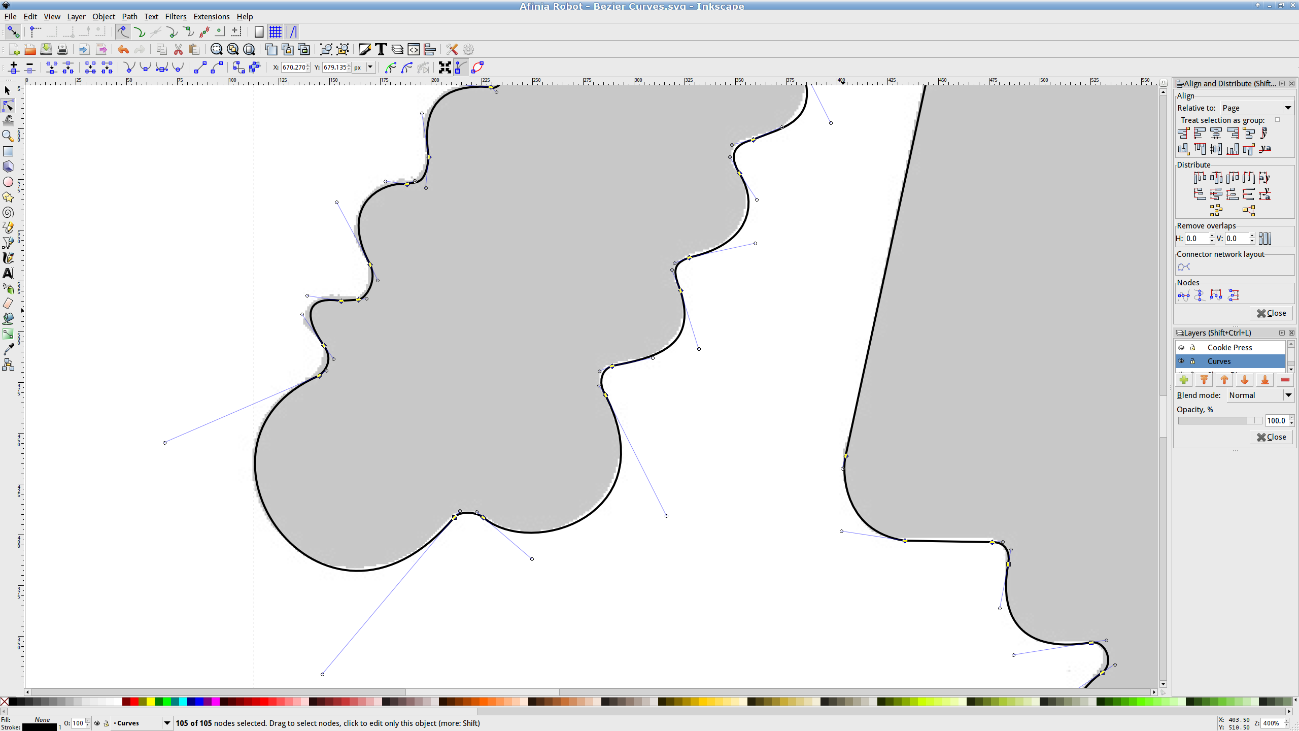
Import the bitmap image into Inkscape. In principle, you can auto-trace the bitmap outline and clean it up manually, but a few iterations of that convinced me that it wasn’t worth the effort. Instead, I used Inkscape’s Bézier Curve tool to drop nodes (a.k.a. control points) at all the inflection points around the image, then warped the curves to match the outline:
Afinia Robot – Bezier spline fitting
If you’re doing that by hand, you could start with the original scanned image, but the auto-trace function works best with a high-contrast image and, after you give up on auto-tracing, you’ll find it’s easier to hand-trace a high-contrast image.
Anyhow, the end result of all that is a smooth path around the outline of the shape, without all the gritty details of the pixelated version. Save it as an Inkscape SVG file for later reference.
OpenSCAD can import a painfully limited subset of DXF files that, it seems, the most recent versions of Inkscape cannot produce (that formerly helpful tutorial being long out of date). Instead, I exported (using “Save as”) the path from Inkscape to an Encapsulated Postscript file (this is a PNG, as WordPress doesn’t show EPS files):
Afinia Robot – Bezier Curves.eps
It’s not clear what the EPS file contains; I think it’s just a list of points around the path that doesn’t include the smooth Bézier goodness. That may account for the grittiness of the next step, wherein the pstoedit utility converts the EPS file into a usable DXF file:
Unfortunately, either the EPS file doesn’t have enough points on each curve or pstoedit automatically sets the number of points and doesn’t provide an override: contrary to what you (well, I) might think, the -splineprecision option doesn’t apply to whatever is in the EPS file. In any event, the resulting DXF file has rather low-res curves, but they were good enough for my purposes and OpenSCAD inhaled the DXF and emitted a suitable STL file:
Afinia Robot – shape slab
To do that, you set the Layout variable to “Slab”, compile the model, and export the STL.
Being interested only in the process and its results, not actually cutting and baking cookies, I tweaked the OpenSCAD parameters to produce stumpy “cutters”:
Afinia Robot – solid model
You do that by setting the Layout variable to “Build”, compile the model, and export yet another STL. In the past, this seemed to be a less fragile route than directly importing and converting the DXF at each stage, but that may not be relevant these days. In any event, having an STL model of the cookie may be useful in other contexts, so it’s not entirely wasted effort.
Run the STL through Slic3r to get the G-Code as usual.
The resulting model printed in about 20 minutes apiece on the M2:
Robot Cutter – stumpy version
As it turns out, the fact that the M2 can produce ready-to-use cutters, minus the raft, is a strong selling point.
Given a workable model, the next step was to figure out the smallest possible two-thread-wide cutter blade, then run variations of the Extrusion Factor to see how that affected surface finish. More on that in a while.
The OpenSCAD source isn’t much changed from the original Tux Cutter; the DXF import required different scale factors:
// Robot cookie cutter using Minkowski sum
// Ed Nisley KE4ZNU - Sept 2011
// August 2013 adapted from the Tux Cutter

Layout = "Build";				// Build Slab

//- Extrusion parameters - must match reality!

ThreadThick = 0.25;
ThreadWidth = 0.40;

function IntegerMultiple(Size,Unit) = Unit * ceil(Size / Unit);

MaxSize = 150;				// larger than any possible dimension ...

Protrusion = 0.1;

//- Cookie cutter parameters

Size = 95;

TipHeight = IntegerMultiple(3.0,ThreadThick);
TipThick = 1.5*ThreadWidth;			// 1.5* = thinnest 2-thread wall, 1.0* thread has gaps

WallHeight = IntegerMultiple(1.0,ThreadThick);
WallThick = 4.5*ThreadWidth;

LipHeight = IntegerMultiple(1.0,ThreadWidth);
LipThick = IntegerMultiple(5,ThreadWidth);

//- Wrapper for the shape of your choice

module Shape(Size) {
  Robot(Size);
}

//- A solid slab of Tux goodness in simple STL format
// Choose magic values to:
//		center it in XY
//		reversed across Y axis (prints with handle on bottom)
//		bottom on Z=0
//		make it MaxSize from head to feet

module Tux(Scale) {
  STLscale = 250;
  scale(Scale/STLscale)
	translate([105,-145,0])
	  scale([-1,1,24])
		import(
		  file = "/mnt/bulkdata/Project Files/Thing-O-Matic/Tux Cookie Cutter/Tux Plate.stl",
		  convexity=5);
}

module Robot(Scale) {
    STLscale = 100.0;
    scale(Scale / STLscale)
			scale([-1,1,10])
				import("/mnt/bulkdata/Project Files/Thing-O-Matic/Pinkie/M2 Challenge/Afinia Robot.stl",
					convexity=10);
}

//- Given a Shape(), return enlarged slab of given thickness

module EnlargeSlab(Scale, WallThick, SlabThick) {

	intersection() {
	  translate([0,0,SlabThick/2])
		cube([MaxSize,MaxSize,SlabThick],center=true);
	  minkowski(convexity=5) {
		Shape(Scale);
		cylinder(r=WallThick,h=MaxSize,$fn=16);
	  }
	}

}

//- Put peg grid on build surface

module ShowPegGrid(Space = 10.0,Size = 1.0) {

  RangeX = floor(100 / Space);
  RangeY = floor(125 / Space);

	for (x=[-RangeX:RangeX])
	  for (y=[-RangeY:RangeY])
		translate([x*Space,y*Space,Size/2])
		  %cube(Size,center=true);

}

//- Build it

ShowPegGrid();

if (Layout == "Slab")
	Shape(Size);

if (Layout == "Build")
	difference() {
	union() {
		translate([0,0,(WallHeight + LipHeight - Protrusion)])
		EnlargeSlab(Size,TipThick,TipHeight + Protrusion);
		translate([0,0,(LipHeight - Protrusion)])
		EnlargeSlab(Size,WallThick,(WallHeight + Protrusion));
		EnlargeSlab(Size,LipThick,LipHeight);
	}
	Shape(Size);					// punch out cookie hole
	}
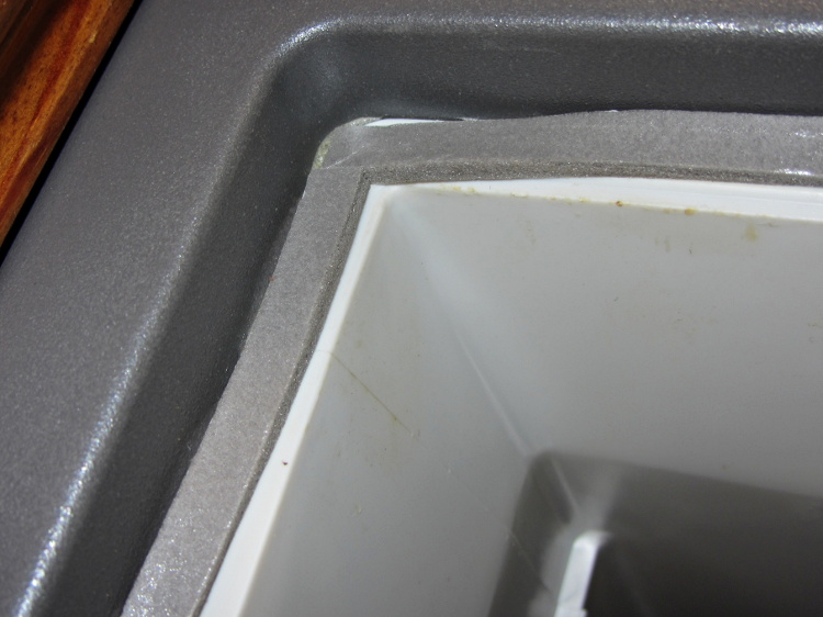
A bit of rummaging in the Big Box o’ Weatherstripping produced the stub end of a spool bearing 1/4 x 1/8 foam tape that exactly fills the gap between the Basement Safe’s door and liner:
Basement Safe – Foam door seal – latch side
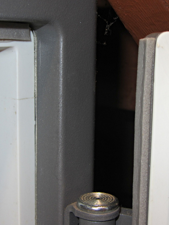
The hinge side of the door has tape between the door liner and the safe wall, because that closes in compression rather than shear:
Basement Safe – Foam door seal – hinge side
There should be a big bump in the humidity record marking that installation, but I don’t expect any immediate difference. If the silica gel lasts more than two months, I’ll consider it a win.
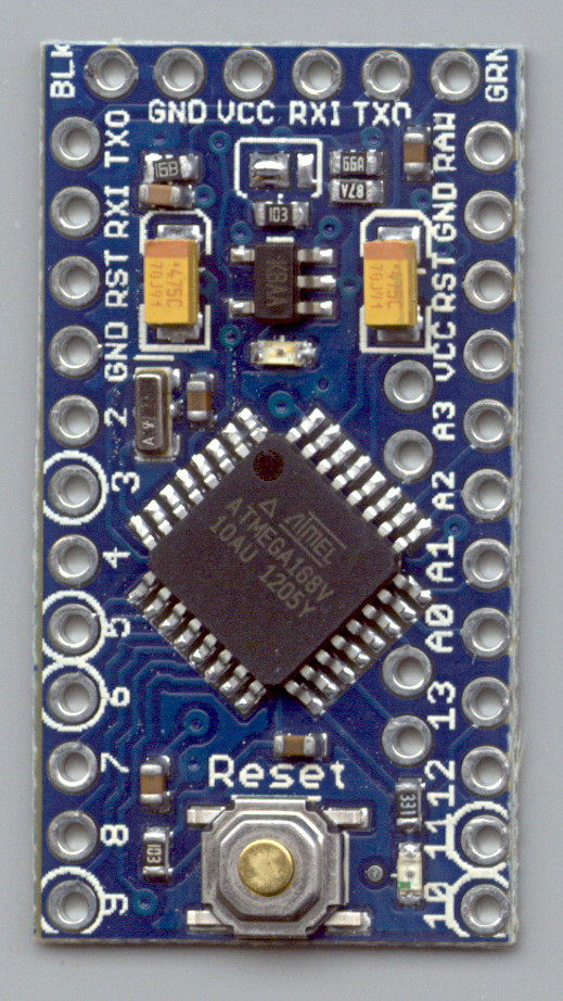
Measured from the Official PCB Layout, with the board origin at the lower-left corner of the PCB, down there by the D9 pin, in mils (0.001 inch):
D9 = (50,50)
D10 = (650,50)
A5 = (535,805)
A4 = (535,705)
A7 = (535,393)
A6 = (535,293)
FTDI header = (100,1250) to (600,1250)
Reset button = (350,105)
D13 LED = (540,100)
PWR LED = (350,850)
Upper fiducial = (160,1140)
Lower fiducial = (490,100)
Subtract 50 mils from each of those coordinates to put the origin at the middle of the D9 pin, which may be more useful. Doing that in inches produces:
D9 = (0.000,0.000)
D10 = (0.600,0.000)
A5 = (0.485,0.755)
A4 = (0.485,0.655)
A7 = (0.485,0.343)
A6 = (0.485,0.243)
FTDI header = (0.050,1.200) to (0.550,1.200)
Reset button = (0.300,0.055)
D13 LED = (0.490,0.050)
PWR LED = (0.300,0.800)
Upper fiducial = (0.110,1.090)
Lower fiducial = (0.440,0.050)
Trust, but verify…
Yes, this is a knockoff PCB from the usual eBay vendor, not from Sparkfun. Contents may settle during shipment. Enlarged to show texture. Your mileage may vary. No warranty, either express or implied, no lie. Do not eat.
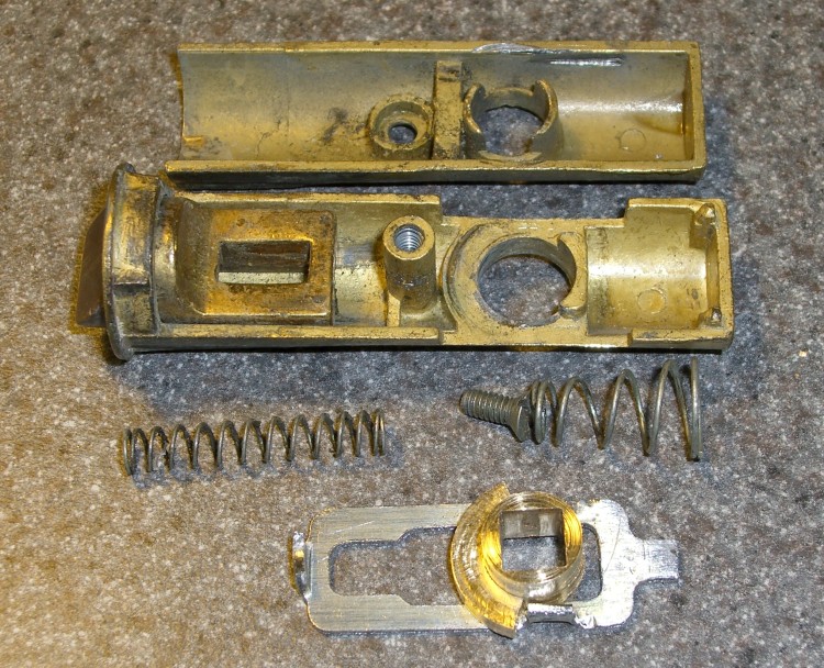
The discussion following that post on getting feature coordinates from an existing part reminded me of an old project that I’d written up for Digital Machinist: making repair parts for the half-century old storm doors on our house. Here’s the whole latch, with a replacement drawbar and cam:
Latch Assembly
The other side of the drawbar and cam:
Door Latch Parts
An early version of the drawbar that engages the latch strike and gets pulled by cam:
New and Old latch pulls
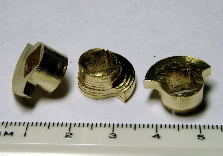
Three iterations on a cam; the messed-up one in the center, IIRC, helped track down an EMC2 bug:
Latch Cams
Now that I look at it again, there’s nowhere near enough meat around that square hole for a 3D printed plastic part… so the notion of printing the complex part of the cam and adding wear bars along those ears just isn’t going to work.
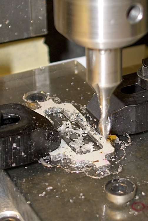
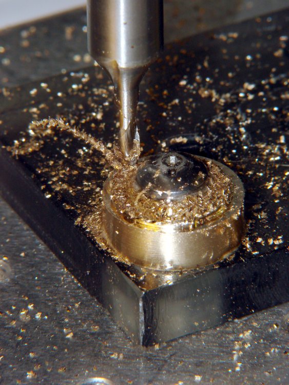
I made a fixture for the Sherline CNC mill to hold the drawbar for inside milling:
Latch pull – Inside milling
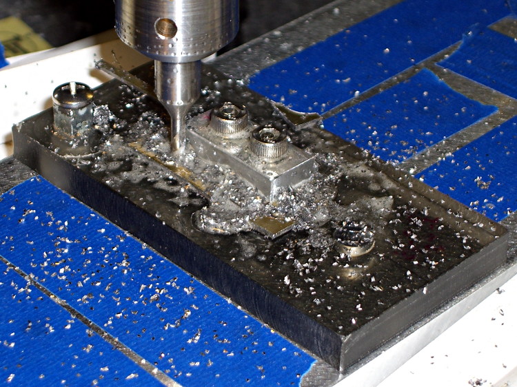
Then a block screwed down in the middle clamps the drawbar in the same place for outside milling:
Latch pull – Outside milling
The square post in the left rear corner holds the cam:
Latch Cam – First Attempt
Note that I had to file the square hole before milling the cam shape, which meant that if the CNC process screwed up, all that handwork went into the show-n-tell bin… which I’m not going to show you.
I used an early version of the grid-overlay technique to map out the drawbar coordinates; this was an illustration for the column:
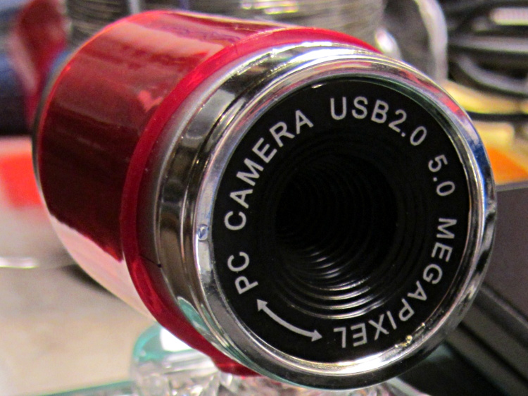
A brace of “Fashion” USB video cameras arrived from halfway around the planet. According to the eBay description and the legend around the lens, they’re “5.0 Megapixel”:
Fashion USB camera – case front
The reality, of course, is that for five bucks delivered you get 640×480 VGA resolution at the hardware level and their Windows driver interpolates the other 4.7 megapixels. VGA resolution will be good enough for my simple needs, particularly because the lens has a mechanical focus adjustment; the double-headed arrow symbolizes the focus action.
But the case seemed entirely too bulky and awkward. A few minutes with a #0 Philips screwdriver extracted the actual camera hardware, which turns out to be a double-sided PCB with a lens assembly on the front:
Fashion USB video – case vs camera
The PCB has asymmetric tabs that ensure correct orientation in the case:
Fashion USB camera – wired PCB rear
In order to build an OpenSCAD model for a more compact case, we need the dimensions of that PCB and those tabs…
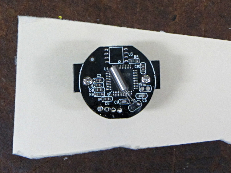
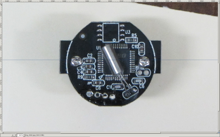
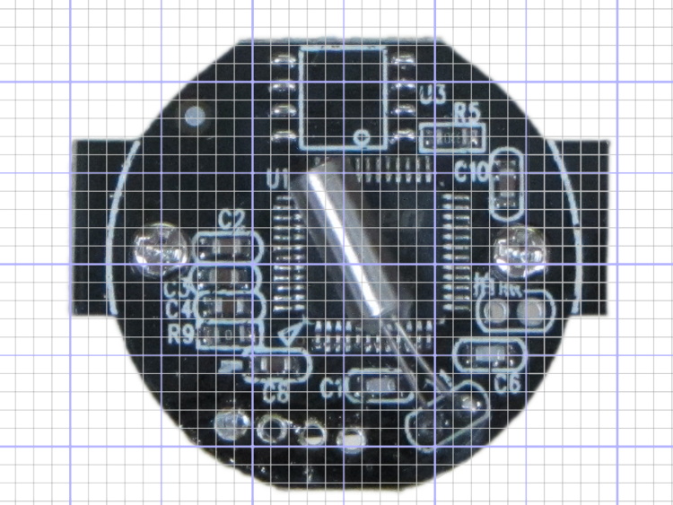
Start with a picture of the back of the PCB against white paper, taken from a few feet to flatten the perspective:
img_3300 – Camera PCB on white paper
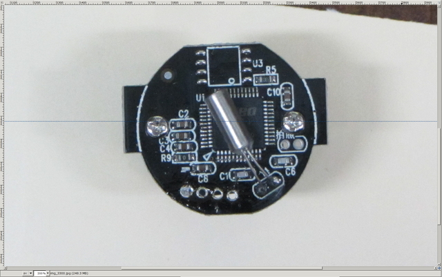
Load it into The GIMP, zoom in, and pull a horizontal guide line down to about the middle of the image:
Camera PCB – horizontal guide – scaled
Rotate to align the two screws horizontally (they need not be centered on the guide, just lined up horizontally):
Camera PCB – rotated to match horizontal guide – scaled
Use the Magic Scissors to select the PCB border (it’s the nearly invisible ragged dotted outline):
Camera PCB – scissors selection – scaled
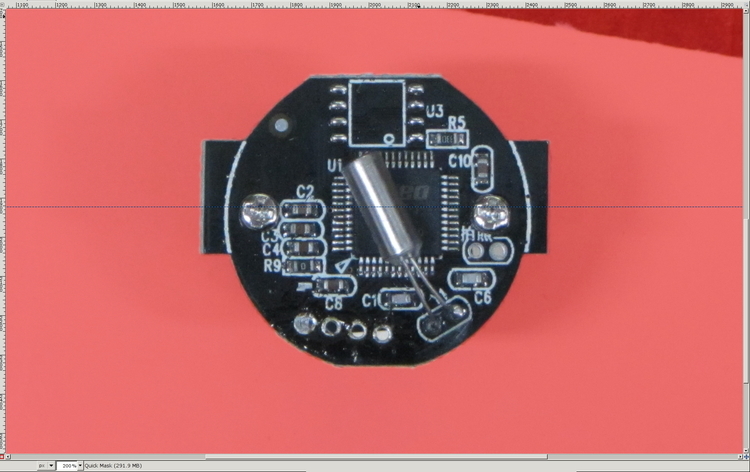
Flip to Quick Mask mode and clean up the selection as needed:
Camera PCB – quick mask cleanup – scaled
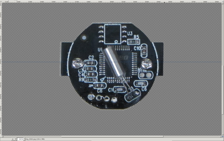
Flip back to normal view, invert the selection (to select the background, not the PCB), and delete the background to isolate the PCB:
Camera PCB – isolated – scaled
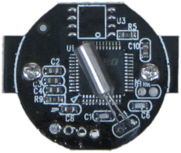
Tight-crop the PCB and flatten the image to get a white background:
Camera PCB – isolated – scaled
Fetch some digital graph paper from your favorite online source. The Multi-color (Light Blue / Light Blue / Light Grey) Multi-weight (1.0×0.6×0.3 pt) grid (1 / 2 / 10) works best for me, but do what you like. Get a full Letter / A4 size sheet, because it’ll come in handy for other projects.
Open it up (converting at 300 dpi), turn it into a layer atop the PCB image, use the color-select tool to select the white background between the grid lines, then delete the selection to leave just the grid with transparency:
Camera PCB with grid overlay – unscaled
We want one minor grid square to be 1×1 mm on the PCB image, sooo…
Accurately measure a large feature on the real physical object: 27.2 mm across the tabs
Drag the grid to align a major line with one edge of the PCB
Count the number of minor square across to the other side of the image: 29.5
Scale the grid overlay layer by image/physical size: 1.085 = 29.5/27.2
Drag the grid so it’s neatly centered on the object (or has a major grid intersection somewhere useful)
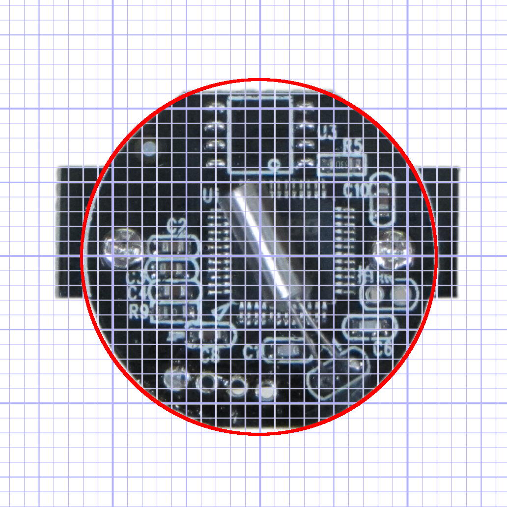
That produces a calibrated overlay:
Camera PCB with grid overlay
Then it’s just a matter of reading off the coordinates, with each minor grid square representing 1.0 mm in the real world, and writing some OpenSCAD code…