Ed Nisley's Blog: Shop notes, electronics, firmware, machinery, 3D printing, laser cuttery, and curiosities. Contents: 100% human thinking, 0% AI slop.
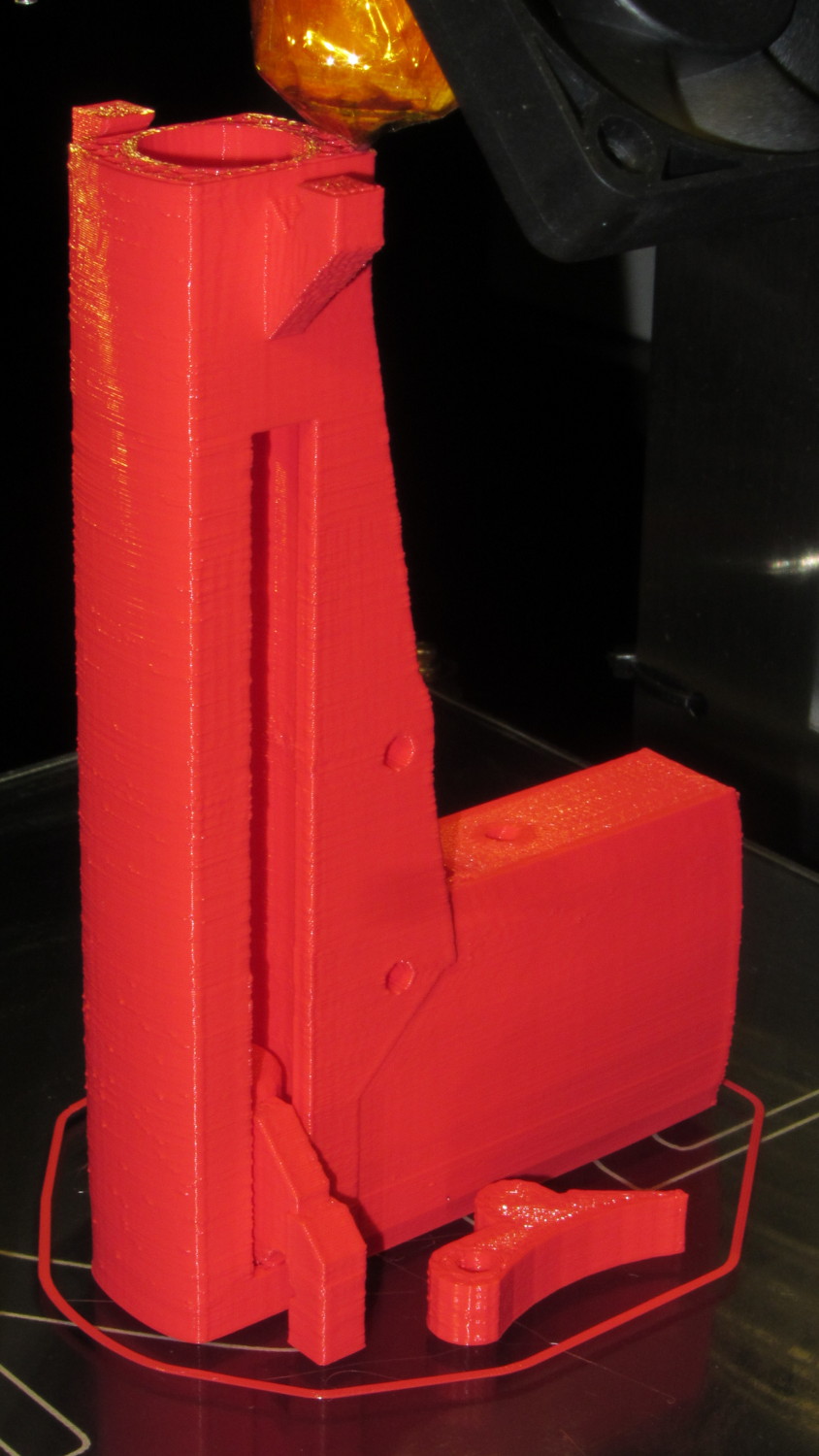
As you can tell from the stock Makergear HBP, I printed it a while ago. It’s the full-length version of that classic, not the shortened Barbie Pistol for the Thing-O-Matic which has been fending off zombies for the last three years (unsuccessfully, from what I hear).
The finished product is a bit ungainly:
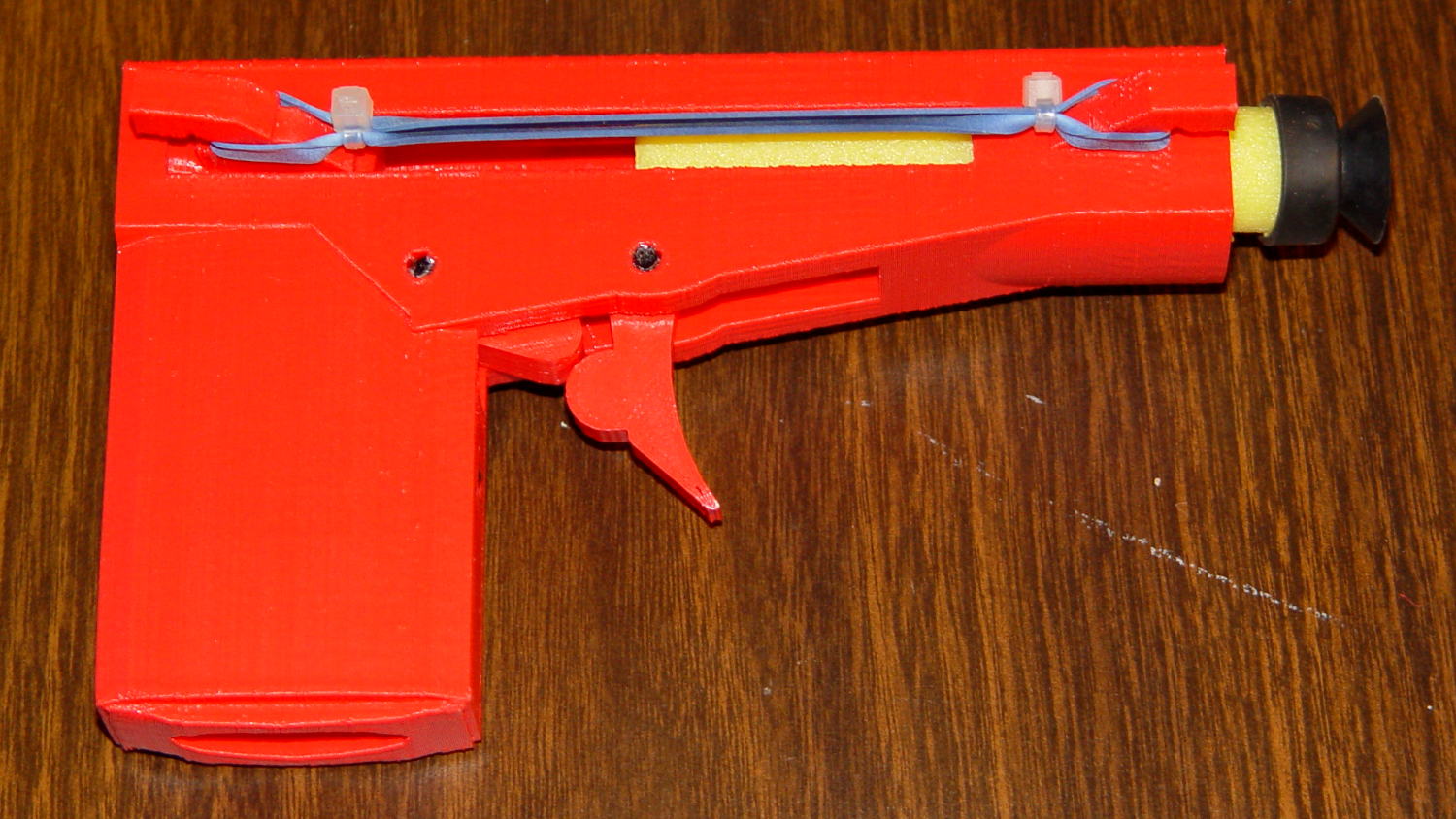
Nerf pistol – loaded
That’s not the proper Nerf dart for the thing, but it’s scavenged from tag sale debris and some day I’ll pick up a pack of the skinny ones.
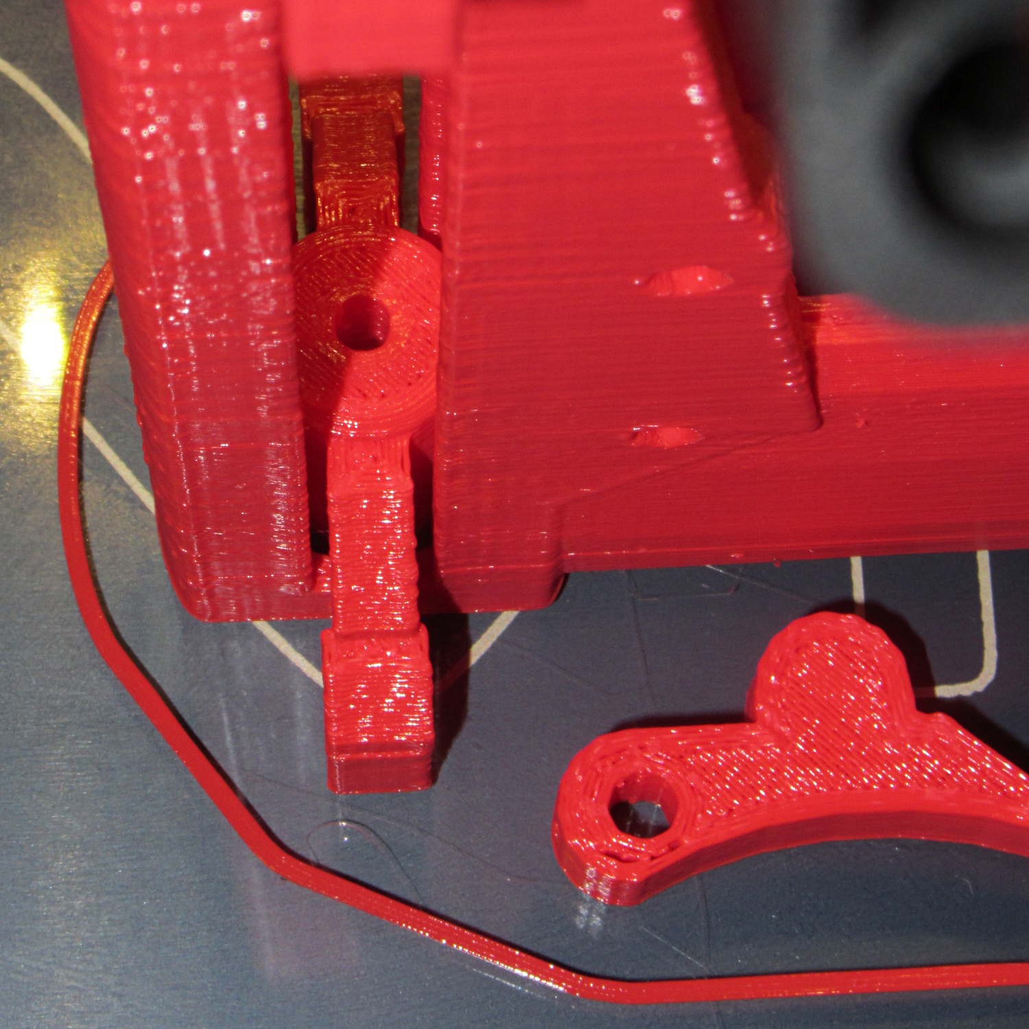
All the pivot points and the sear spring are 3 mm black ABS filament, mostly for contrast. They’re glued in with dabs of Oatey clear PVC cement, the kind with tetrahydrofuran in addition to the usual hellish mix of acetone and MEK.
I bring it along to my show-n-tells, just so I can say I downloaded and printed a gun long before Defense Distributed made it trendy. Haven’t gotten into any trouble yet, but I’m sure some Zero Tolerance regime will bust my ass one of these days.
It was a big hit with the adolescent males at a Squidwrench event, for some reason. [grin]
After enduring my OpenSCAD solid modeling class, The Might Thor conjured up a solid model of a Thing he wanted and asked if it was buildable. I added a pair of hemispheres to round off the tops, thinned and widened the baseplate for better adhesion, and Fired the M2:
Double Helix – on platform
I thought the overhang was aggressive, but, while it’s not perfect, it’s not nearly as awful as I expected. Perhaps tinkering with a slightly lower extrusion temperature would help.
It’s far less blocky than the stuff I build!
The OpenSCAD model is his; you get to figure it out on your own. Hint: linear_extrude a pair of circles with a twist.
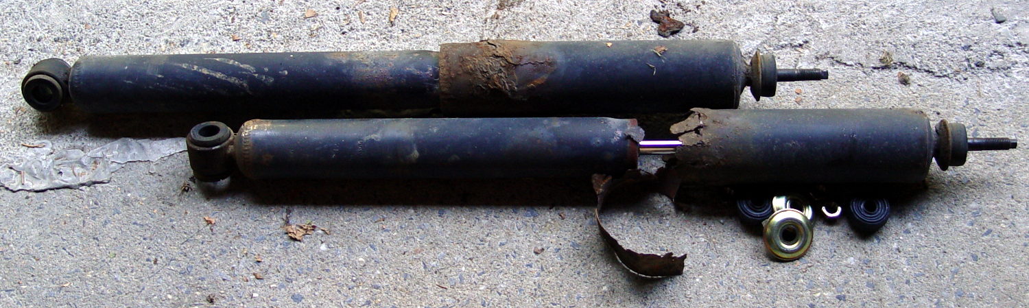
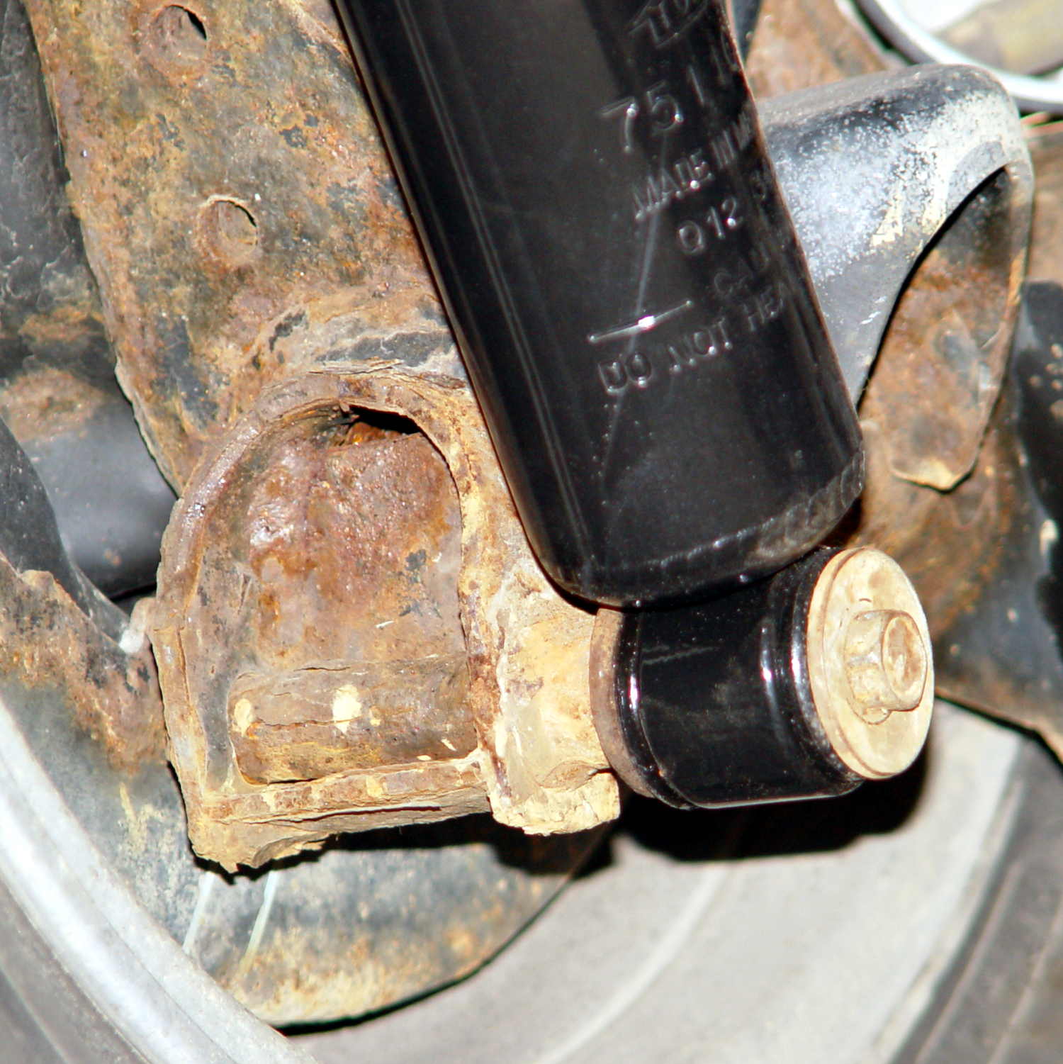
After the last annual inspection, the Nice Man told me that the rear shocks were rusted out and, although they still worked and he couldn’t fail the van, he wished he could. After 13 years and 88 k miles, yeah, they looked pretty grim:
Sienna OEM rear shocks – removed
The loose steel snippet came from the bottom of the outer shield; it had completely rusted off and dropped free around the lower mount. I suppose that was what got his attention.
Anyhow, the removal went astonishingly well:
Back the van out of the garage until the wheels line up with drop to the driveway apron
Pop inside dress covers over the struts
Remove top jam nuts, cushion, cups
Remove bottom bolt from wheel carrier (easily!)
Spritz penetrating on rubber bushing
Compress shock, twist until bushing slides free
And the installation was equally smooth:
Install shock on wheel carrier
Torque bottom bolt (29 ft·lb)
Aim strut at hole in body
Cut restraining wire, guide strut through hole
Install OEM bottom cup, new cushion & cup, new nylock nut
Tighten to same length as OEM nut
Install dress covers
The OEM cup fits snugly into the body hole to center the strut, so it seemed like a Good Idea to reuse it. Despite the rust stain inside the body, it was in reasonable condition.
You’re supposed to jack the van up while fiddling around underneath, but the driveway slopes down from the garage enough to provide access. I did chock the wheels, of course, but not jacking the van and putting it on stands looked like a major safety win right there.
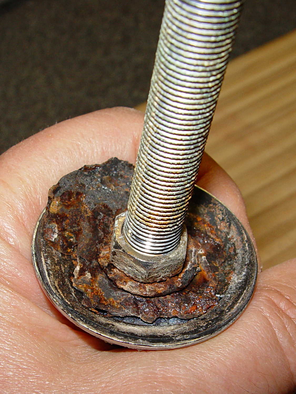
The bottom view, which shows the effect of a dozen New York State winters on ordinary steel:
Sienna replacement rear shocks – bottom
The top view, which shows that the bushings did leak a bit of water over the last decade:
Sienna replacement rear shocks – top
Done!
I suppose, just for completeness, I should do the front shocks, but those aren’t nearly as easy and I’d have to start by buying a spring compressor.
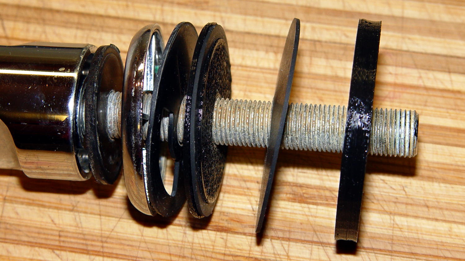
The kitchen sink has a small faucet that used to connect directly to the well out back, but now delivers town water from a line bypassing the water softener. The large steel washer below the sink deck has been shedding rust for a while and finally disintegrated:
Kitchen faucet – rusted washer assembly
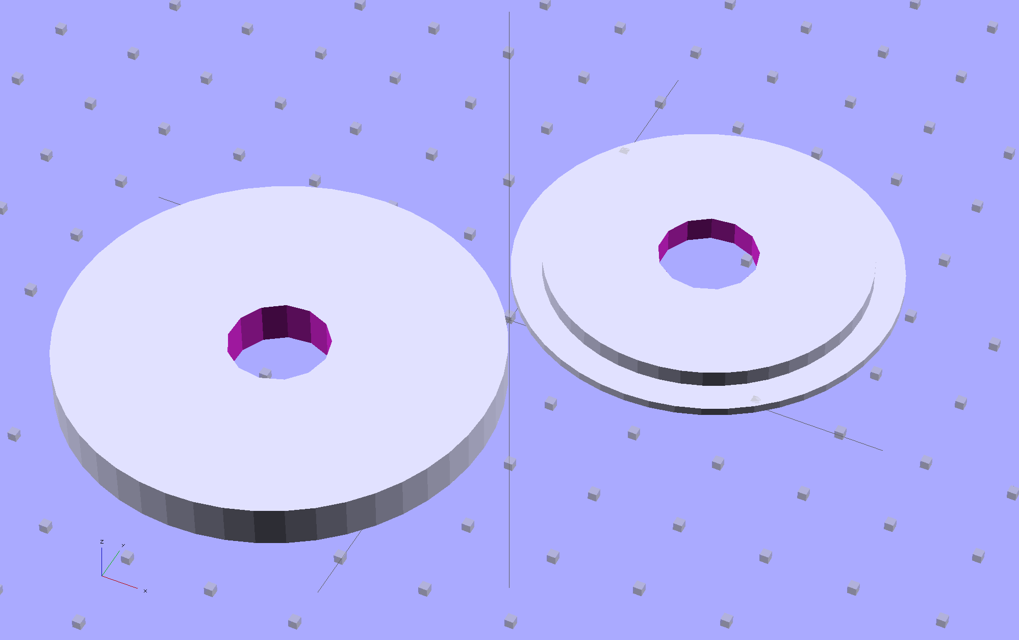
Well, this is a perfect application for plastic, not steel, so I conjured up a pair of disks:
Sink Base – Build
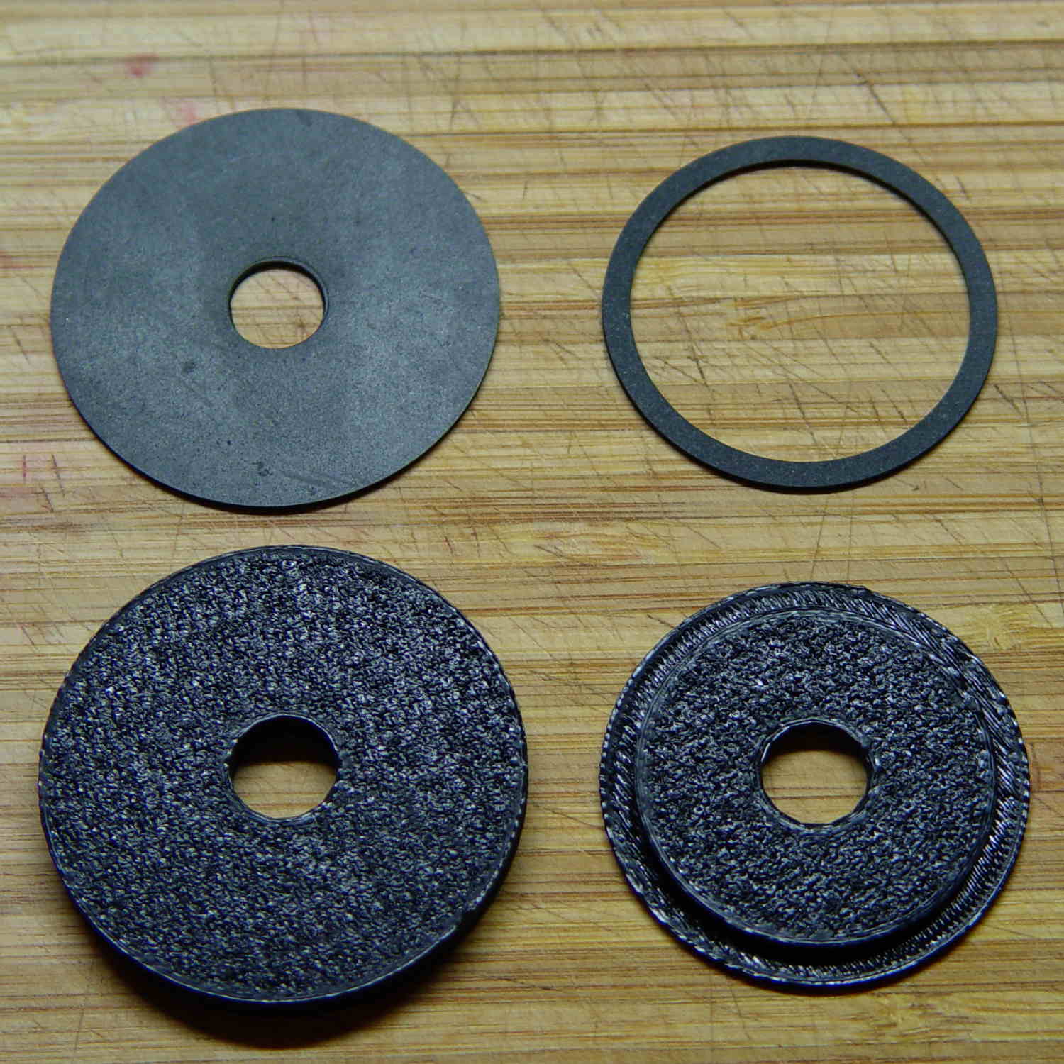
The large flat one goes below the sink deck in place of the steel washer and the smaller part of the stepped disk fits inside the deck opening to stabilize the faucet:
Sink Base – Show
The two dark rings bracketing the deck between the orange plastic disks represent a pair of gaskets / washers / seals cut from 1 mm rubber sheet with a straight razor toting compass:
Kitchen faucet – plastic disks and rubber deck washers
Just for fun, I used Slic3r’s Hilbert Curve top and bottom fill pattern. It produces a nice, grainy texture that feels appropriate for anything needing a non-slip grip (at least on the top, as the bottom surface is glass-smooth).
Everything stacks up thusly, with the top dark ring representing a rubber seal that came with the faucet:
Sink Base – Assemble
It looks about the same in real life, albeit minus all the colors:
Kitchen faucet – fitting stack
The black plastic and black rubber blend together and vanish amid all the chrome:
Kitchen faucet – assembled
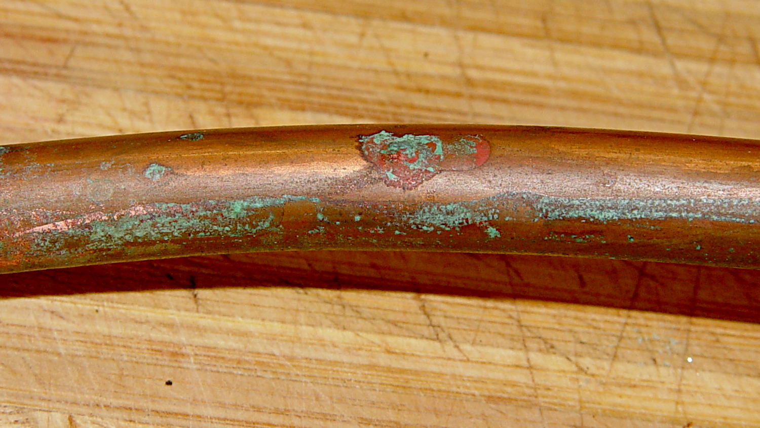
Alas, when I turned the water on, Mary said “That doesn’t sound right…” at about the same time I discovered a fine mist under the sink. See if you can spot the problem:
Kitchen faucet – corroded copper tube
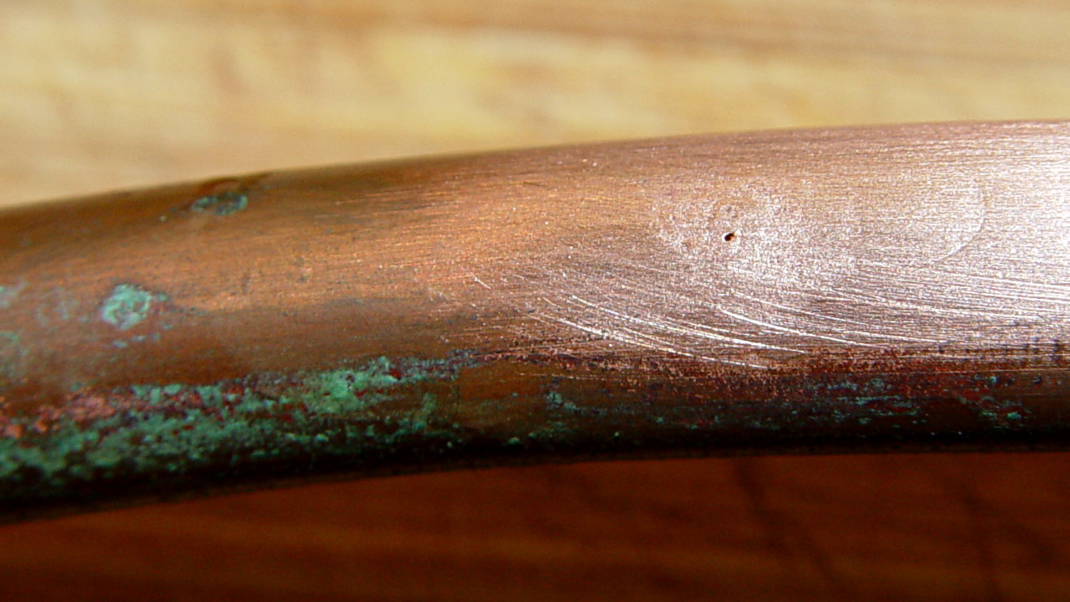
A shined-up view should make it obvious:
Kitchen faucet – corroded copper tube – pinhole
A trip to the precious metals aisle of the Big Box Home Repair Store produced a roll of 3/8 inch copper tubing, although I should have the stub end of that original roll somewhere in the heap. The fitting at the bottom of the faucet turned out to be completely non-standard and I had to re-use it with the new tubing, but it still sealed perfectly.
I hate plumbing jobs. That fix better last for another decade…
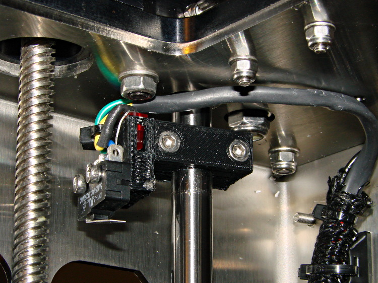
Fairly obviously, taping the Z-min switch to the back of the X gantry isn’t a long-term solution. There’s just enough clearance between the extruder and the X gantry for the switch, so I made a small block with clearance holes for the screws holding the X axis linear slide rail in place and tapping holes for the M2.5×0.45 screws in the switch:
Z-min Front Mount Switch Block – solid model
Not much to it, is there? That printed just fine with the taped-in-place switch and exactly fit the screws; the rail screws dropped right through the holes and the switch screws tapped their way in.
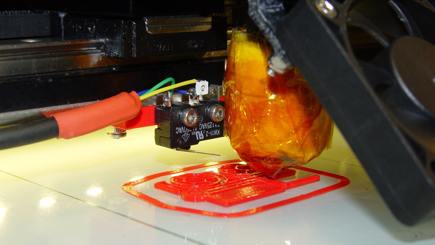
The stock M2 cable reaches to the front of the X gantry, but only with the switch mounted to the left side:
M2 Z-min switch – left gantry
Those are 25 mm M3 screws shortened to about 19 mm; the one on the right looks a bit short to me, too.
Unfortunately, that spot on the gantry is the only place you can pick up the M2 with one hand: it balances perfectly when you (well, I) put four fingers between the five leftmost rail screws. It’s a beast to carry any other way, so that switch had to move.
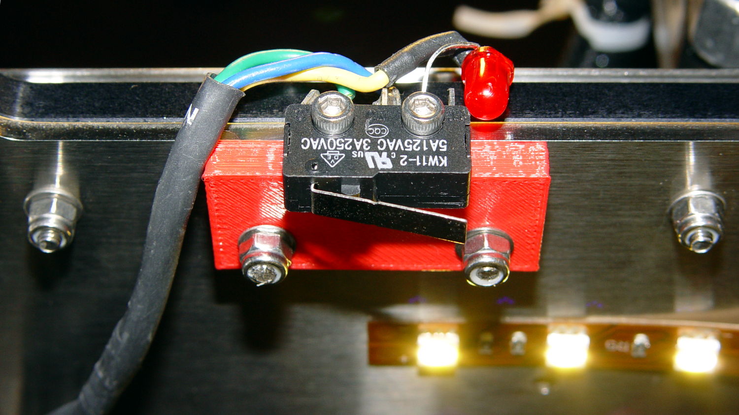
So I spliced in a snippet of six conductor cable, just so I could match the original color code, replaced the red through-hold LED with a blue SMD LED, and moved it to the middle of the gantry:
M2 Z-min switch – center gantry
The view from below shows a sticky clamp holding a bight of the original cable and a small clamp (bent & drilled from a steel strap) holding the new cable in place:
M2 Z-min switch – center gantry – bottom view
It’s once again possible to grab the printer and lug it away…
The first test piece was Madscifi’s classic Tiny Toy Dump Truck, because I needed a show-n-tell tchotchke for a Squidwrench meeting:
M2 Z-min switch – center gantry – in action
Yes, that dangling switch lever looks precarious, but it can’t touch the platform because the nozzle is below it.
With the switch in place, I melted a blob of solder atop the brass tubing on the platform, popped it off, and removed the residue with a razor scraper.
Before doing the truck, however, I had to recalibrate the Z switch and make the homing sequence do a different dance:
Home Y and leave the platform at the rear
Home X and move it to the far right to clear the platform
Home Z against the platform glass
The complete start.gcode sequence (which isn’t really a separate file in Slic3r, but the notation helps keep things straight):
;-- Slic3r Start G-Code for M2 starts --
;  Ed Nisley KE4NZU - 7 Oct 2013
; Z-min switch at platform, must move nozzle to X=130 to clear platform
M140 S[first_layer_bed_temperature]	; start bed heating
G90				; absolute coordinates
G21				; millimeters
M83				; relative extrusion distance
M84				; disable stepper current
;G4 S3			; allow Z stage to freefall to the floor
G28 Y0			; home Y to be sure of clearing probe point in X
G92 Y-127 		; set origin to 0 = center of plate
G28 X0			; home X
G92 X-95		; set origin to 0 = center of plate
G1 X130 F30000	; move off platform to right side
G28 Z0			; home Z
G92 Z-4.55		; set origin to measured z offset
G0 Z10 F2000    ; get nozzle clearance
G0 X0 Y-124 Z3.0 F20000     ; set up for priming
M190 S[first_layer_bed_temperature]	; wait for bed to finish heating
M109 S[first_layer_temperature]	; set extruder temperature and wait
G1 Z0.0 F2000	; plug extruder on plate
G1 E10 F300		; prime to get pressure
G1 Z5 F2000		; rise above blob
G1 X5 Y-123 F30000	; move away from blob
G1 Z0.0 F2000		; dab nozzle to remove outer snot
G4 P1			; pause to clear
G1 Z0.5 F2000		; clear bed for travel
;-- Slic3r Start G-Code ends --
The G92 Z-4.55 instruction sets the Z position (without moving the stage) to the measured difference between the switch trip point and the nozzle tip.
Finding that value is a two-step process:
Manually home Z against the platform (with the nozzle off to the right!)
Issue G92 Z0 to define the switch trip point as Z=0.0
Move the Z stage downward by a known distance so it clears the nozzle
Move the nozzle over the platform
Measure the distance between nozzle and platform (perhaps with a tapered gauge)
Subtract that measurement from the distance you moved the nozzle
For example, I lowered the platform by 7.0 mm and measured 2.6 mm between the nozzle and the platform, so the G92 value = -7.0 + 2.6 = -4.4. Put that in the start.gcode G92 instruction: G92 Z-4.4.
That’ll get you in the ballpark, so print a thinwall open box and measure its top-to-bottom height at the corners. The second box came out about 4.85 mm tall, which means the nozzle was 0.15 mm too close to the platform: subtract 0.15 from the G92 setting: -4.4 – 0.15 = -4.55.
The next thinwall box came out exactly 5.0 mm tall.
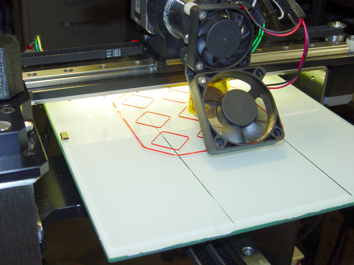
Then I could print that truck, which came out just fine, apart from the usual slight drooping where the filament must bridge the left side of the dump box:
M2 Tiny Toy Dump Truck test piece
After breaking one errant strand from the left side of the hinge, everything moved smoothly.
I must tinker up some G-Code to measure the switch closure point along the length of the platform, which would detect front-to-back tilt.
The OpenSCAD source code for the switch mounting block:
// Block to mount M2 Z-min switch on X gantry
// Ed Nisley KE4ZNU - Oct 2013

//- Extrusion parameters - must match reality!

ThreadThick = 0.25;
ThreadWidth = 0.40;

function IntegerMultiple(Size,Unit) = Unit * ceil(Size / Unit);

Protrusion = 0.1;

HoleWindage = 0.2;

//- Sizes

SwitchScrewOD = 2.05;					// microswitch screw tapping
SwitchScrewOC = 9.5;					//  ... on-center spacing

GantryScrewOD = 3.0;					// X rail screw clearance
GantryScrewOC = 25.0;					//  ... on-center spacing along X
GantryScrewOffset = 12.0;				//  ... Y offset from gantry front

BlockSize = [1.5*GantryScrewOC,17.0,5.0];			// XYZ dimensions as mounted

SwitchScrewLength = BlockSize[1] - 5*ThreadWidth;	// net length of switch screws
echo ("Max switch screw length: ",SwitchScrewLength + 5.0);		// ... allow switch thickness

//- Adjust hole diameter to make the size come out right

module PolyCyl(Dia,Height,ForceSides=0) {			// based on nophead's polyholes

  Sides = (ForceSides != 0) ? ForceSides : (ceil(Dia) + 2);

  FixDia = Dia / cos(180/Sides);

  cylinder(r=(FixDia + HoleWindage)/2,h=Height,$fn=Sides);
}

//- Put peg grid on build surface

module ShowPegGrid(Space = 10.0,Size = 1.0) {

  RangeX = floor(100 / Space);
  RangeY = floor(125 / Space);

	for (x=[-RangeX:RangeX])
	  for (y=[-RangeY:RangeY])
		translate([x*Space,y*Space,Size/2])
		  %cube(Size,center=true);

}

//- Build it

ShowPegGrid();

difference() {
	translate([-BlockSize[0]/2,-GantryScrewOffset,0])
		cube(BlockSize,center=false);
	for (i=[-1,1]) {
		translate([i*GantryScrewOC/2,0,-Protrusion])
			rotate(-90)
				PolyCyl(GantryScrewOD,(BlockSize[2] + 2*Protrusion));
		translate([i*SwitchScrewOC/2,-(GantryScrewOffset + Protrusion),BlockSize[2]/2])
			rotate([-90,0,0])
				rotate(90)
					PolyCyl(SwitchScrewOD,(SwitchScrewLength + Protrusion));
	}
}
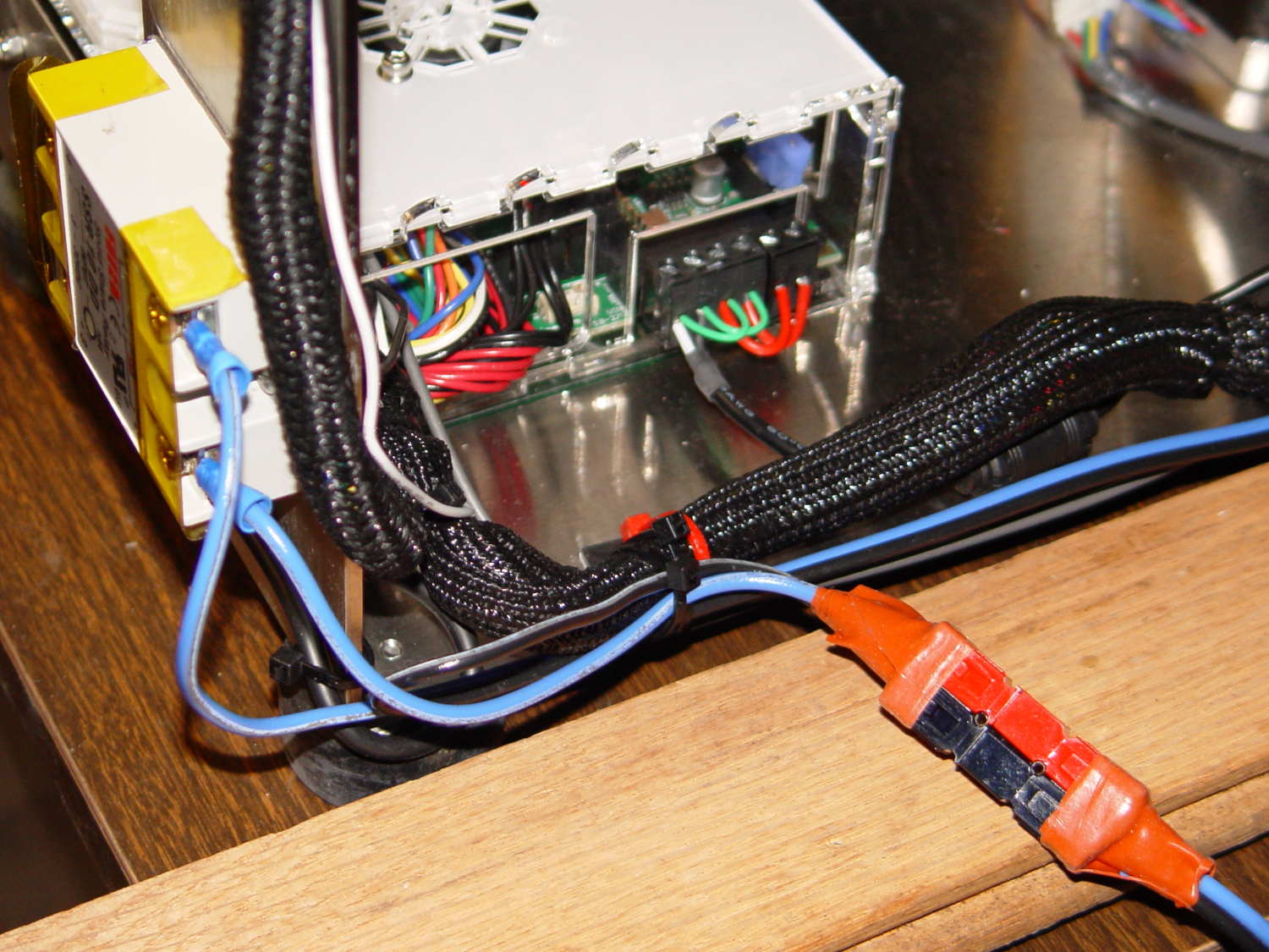
I’d originally planned to drive the new HBP with a boost converter from the 24 V supply brick, but that didn’t quite work out. The arrival of a 36 V brick from halfway around the planet solved that problem, but the RAMBo platform heater’s 15 A ATO fuse restricts it to 24 V and I don’t quite trust that MOSFET for high current applications, either.
Sooo, I went full-frontal Cupcake with a solid state relay screwed to a pair of existing holes (!!!) in the M2’s frame:
M2 – SSR for Improved HBP
Note: that’s a DC-to-DC SSR, not the more common DC-to-AC SSR. Basically, it’s an up-armored optically isolated MOSFET, not a triac, and, yes, capitalizing acronyms and initalisms can be contentious.
Because the RAMBo’s MOSFET now drives the piddly current required to activate the SSR, I rewired the power to apply the M2’s 19.5 V brick to all three inputs by adding two red jumpers on the right side of the Phoenix plugs:
M2 HBP SSR Wiring
The M2’s hulking 12 V brick now resides in the Basement Warehouse’s Power Supply Annex.
The HBP cable comes in from the right side and the 36 V supply arrives through the Powerpole connectors in the lower right. Tucking the ferrite slug on the 19.5 V supply behind the wire loom prevents the cable from pulling the Phoenix connectors out of the RAMBo board at an inopportune moment.
The original M2 HBP wiring got uncomfortably warm carrying the 10+ A for that platform. It would probably work OK at a lower current, but I’d already put Powerpole connectors on the new HBP. So I ran that cable outside the loom and abandoned the original pair inside.
The SSR switches the +36 V wire, leaving the HBP at 0 V when it’s not activated: supply hot → SSR → HBP → supply common. That makes no practical difference, but it feels like a Good Idea. Also, the Kapton tape across the SSR terminals should be barely adequate to prevent contact with random conductive clutter; I’m channeling the true spirit of DIY 3D printing…
I don’t have a connector matching the M2’s 100 kΩ platform thermistor, either, so I just ran the new cable down the outside of the loom and conjured up a two-pin socket for the header on the RAMBo board:
Those are thinwall open boxes that came out 5±0.03 mm tall across the array, so the platform is just about as level / aligned as necessary for my simple needs.
The Z-min switch will move to get rid of that stupid block epoxied to the platform, so I didn’t record the G-Code tweakage…
I applied a tiny rat-tail file to the holes until they became a free sliding fit for the screws.
The wave springs are mostly decoration, as the silicone rubber disks now take the compression load from the screws, and the platform is quite rigidly mounted.
The new platform eliminates the M2’s original aluminum support spider, the aluminum heater & heat spreader, and the corner supports & clips, all of which add up to about 780 g. I didn’t bother changing the Y axis acceleration to match, as all those numbers seem rubbery.
Minus the support spider, the platform rides much lower on the Z axis stage than the M2’s platform. Unfortunately, the Z-min switch clamped to the top of the rear Z-axis guide rod can’t get any higher, even after rearranging the cable and fiddling with the LED:
M2 – Z min limit switch
As a first-pass hack, I moved the switch to the rear of the X gantry and applied Gorilla Tape to hold it in place:
M2 – Z-min switch at rear X gantry
That required a small block to raise the platform enough to activate the switch before hitting the nozzle. I epoxied a snippet of brass rectangle tube to the left edge of the platform, directly under the switch lever:
M2 – Improved HBP – rear switch tab
The awkward position activates the switch with the platform as far to the rear as possible, so that you can’t inadvertently drag the dangling switch lever across the block in the wrong direction.
I think it’s stupid, too, but it let me bring up the printer and make sure all the electronics kept working. The next step was to relocate the switch to a more rational place