Ed Nisley's Blog: Shop notes, electronics, firmware, machinery, 3D printing, laser cuttery, and curiosities. Contents: 100% human thinking, 0% AI slop.
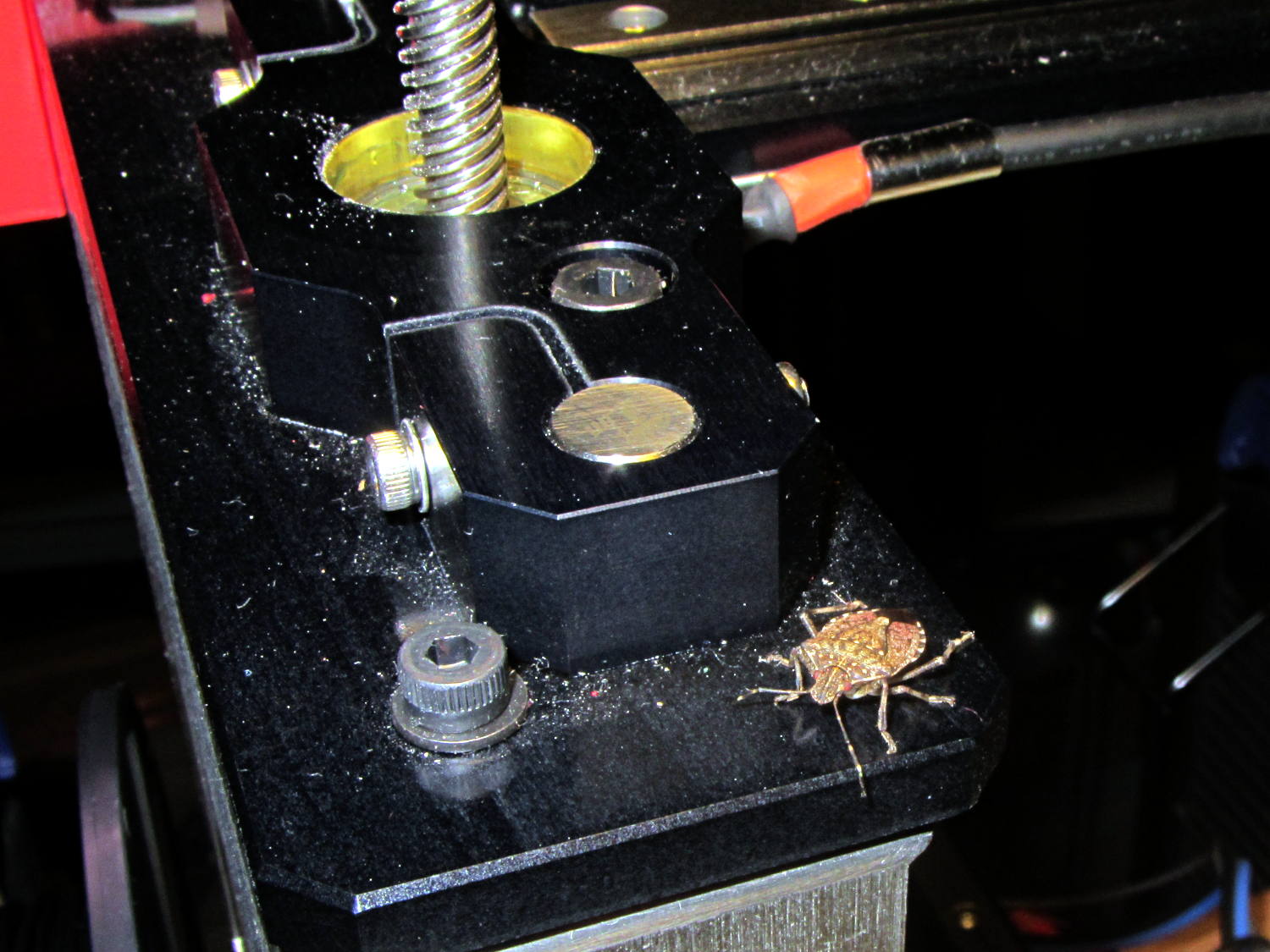
Late in the fall, Brown Marmorated Stink Bugs move indoors to spend the winter; they can infiltrate through the smallest of cracks and seem to show up unannounced in the strangest locations. This one magically appeared on my M2 printer while I was starting it up:
Brown Marmorated Stink Bug on M2 Printer
I unceremoniously flushed its contribution to the gene pool…
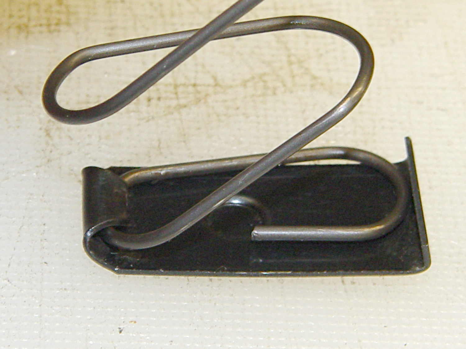
The Browning Hi-Power magazine case has a 12.5° forward angle with respect to the floor plates:
Browning Hi-Power magazine – components
The natural axes lie parallel and perpendicular to the case axis, which means dimensions parallel and perpendicular to the floor plates (horizontal & vertical, respectively) require a bit of trigonometry. This doodle sketches some of the key values, not all of which are hereby asserted to be correct:
Magazine angle doodles
Name the variables:
Slant angle α
Height H along magazine axis
Length L perpendicular to H
Components of H:
vertical = H cos α
horizontal = H sin α
Components of L:
vertical = L sin α
horizontal = L cos α
Extreme point of the tilt at the edge, relative to center point on axis:
vertical = (L/2) sin α
horizontal= (L/2) cos α
Projection of top parallel to axis onto horizontal:
L / cos α
I suppose one could set up functions for all that, but I tend to just hammer out the trig where it’s needed.
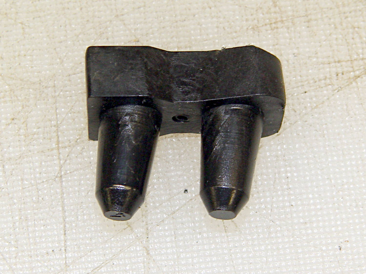
The follower has 15.3 mm long pegs that taper from 8.75 mm to 7 mm, on 14.5 mm centers. The spring compresses down to a little longer than that with 13 rounds atop the follower:
Browning Hi-Power magazine – follower
The top of the follower has a rather complex shape (yes, that’s a crunch toward the front of the ridge):
Browning Hi-Power magazine – follower top
The front view shows more curves:
Browning Hi-Power magazine – follower front
Judging from the online pictures, BHP followers have taken on a wide variety of shapes over the decades, so I’d expect almost anything would work more-or-less well.
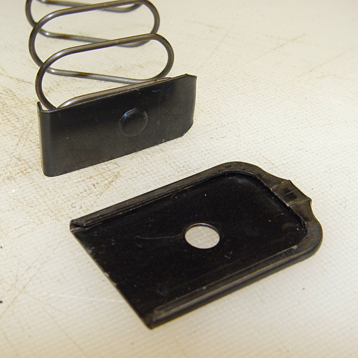
The inner floor plate attaches to the spring and has a 5 mm dia x 1 mm tall boss that matches the hole in the outer floor plate:
Browning Hi-Power magazine – base plates
The hole in the outer floor plate is a scant 5.4 mm, just slightly under the head size of a 3.0×0.5 mm socket head cap screw. The OEM Browning magazines have a centered boss, but some aftermarket magazines move it a millimeter or so to the front or rear. The outer plate seems hard enough to be just about spring steel.
A tab on the front of the inner floor plate (to the left in this picture captures the spring:
Browning Hi-Power magazine – spring inside base plate
The inner plate is 0.75 mm mild steel and may be removable, depending on how tightly the tab got crunched during manufacturing. The tab extends a millimeter or so beyond the spring on the inside of the curve and is about 2 mm tall at that point.
The boss on the inner plate and the hole on the outer plate locate the spring at the proper position and also ensure the outer plate doesn’t accidentally slide off; you must push the boss inward to release the outer plate before sliding it forward. Using a rounded rod lets you push the inner plate far enough inward to release the spring pressure on the outer plate, making it much easier to slide; in fact, for my fingers, I can’t move the outer plate without inserting a rod in the hole.
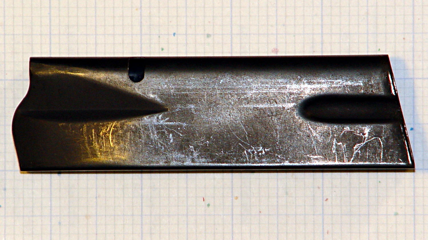
The case is a seamless 0.7 mm thick high-carbon-steel tube with complex curves:
Browning Hi-Power magazine – case on grid paper
The “high carbon” part means that it’s not in the least bendy; a few operations on large presses mashed it into that shape and it’s not going to take on anything else by accident. The feed lips on the top can get bent if you abuse the thing, but that’s about it.
The case is 20.5 x 31.7 mm from the base to the latch hole, 99 mm long in front and 109 mm long in the back. The latch hole is 4.2 x 7.3 mm with a 2.7 mm notch in the front side, 67.2 mm from the base and 27.7 mm from the top. The angle of the case axis with respect to the bottom (on the right) is 12.5°.
Inside measurements at the base: 30.5 x 18.7 mm. The rear corners are essentially right angles and the front curves fit 1/4 inch = 6.3 mm or 9/32 inch = 7.1 mm drills.
The lower flutes are 26 x 6.5 mm, centered on the side (even though it doesn’t look that way), and compress the outside of the case to 16.2 mm and the inside to 14.7 mm. The tabs engaging the outer floor plate are 23 mm edge-to-edge, 10.5 mm and 6.0 mm long, and protrude 1.5 mm from the outside of the case:
Browning Hi-Power magazine – bottom
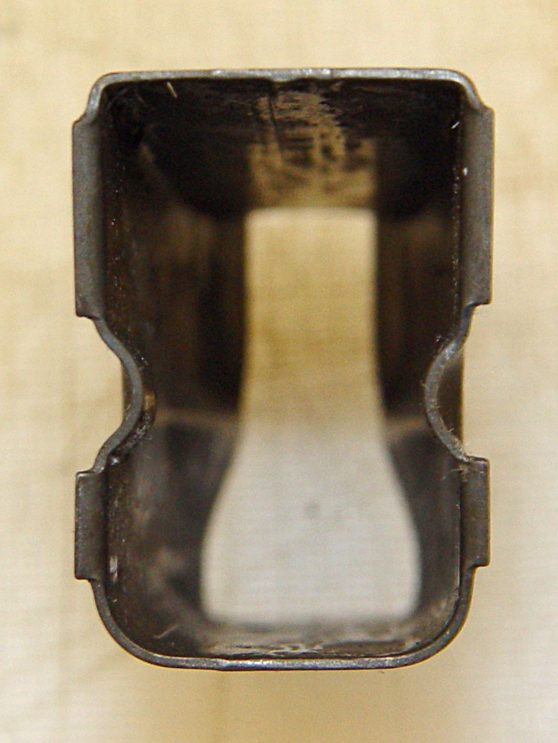
The top of the case is 10.5 mm wide at the rear of the feed lips, with the sharp bend 17.0 mm from the outside of the rear face:
Browning Hi-Power magazine – top
The spring is 1.25 mm = 49 mil wire, 143 mm flat-to-flat high, about 15.1 mm turn-to-turn, 13/32 inch = 10.3 mm ID at the ends, 13.2 mm outside width, 25 mm inside length, and 27 mm outside length. Those don’t quite add up, but the whole thing is, well, springy.
The spring exerts these crudely measured forces:
1 round = 1.1 kg
10 rounds = 2.5 kg
The follower moves 5.3 mm, so the spring constant is very roughly 0.26 kg/mm = 14.8 pound/inch. Aftermarket springs tout their stiffness and come in 5% increments of additional force, so that’s probably not a critical number.
Limiting the capacity of a magazine so that it cannot be “readily” converted back to a higher capacity seems difficult, particularly if you allow disassembling the magazine for proper cleaning and maintenance. If operator safety and proper function isn’t a concern, then many things become possible.
I’ve been doing a lot of fiddly gluing lately and, despite my best efforts, some adhesive collects in the lid’s screw threads. The gummy residue makes it really hard to unscrew the lid without a strap wrench after a few days.
Wrapping two turns of silicone tape around the cap helps tremendously:
According to Wikipedia, Polylactic acid, a.k.a. PLA “is soluble in chlorinated solvents, hot benzene, tetrahydrofuran, and dioxane” and is not soluble in acetone, alcohol, or water.
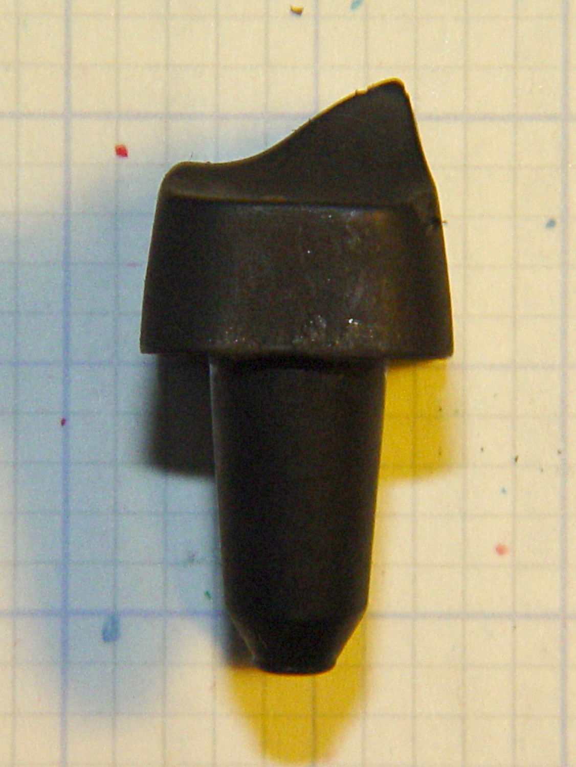
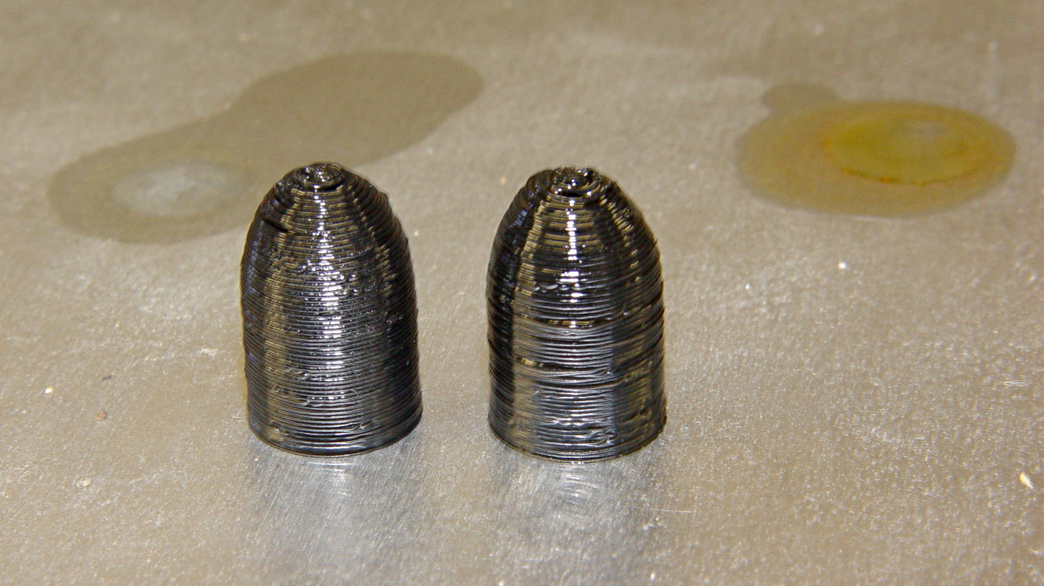
Just to see what happens, I dunked a pair of those 3D printed dummy bullets in Shooter’s Choice Gun Solvent (which has since gone obsolete) and Hoppe’s No. 9 Gun Bore Cleaner (which seems to have been reformulated several times), then let them air-dry in those background puddles:
PLA dummy bullets after solvent bath
Nothing much happened: they’re not soft or gummy, haven’t slumped, and seem undaunted.
That’s in contrast to ABS plastic, which isreadily soluble in acetone and the aromatic hydrocarbons commonly found in solvents used around firearms. Apart from that, ABS would be a slightly better choice on mechanical grounds. I’m not sure the difference really matters for most purposes, given the very wide tolerances on 3D printed objects.
To review, PL 265.00 Section 23 as amended defines a large capacity magazine (a.k.a. “ammunition feeding device”):
23. “Large capacity ammunition feeding device” means a magazine, belt, drum, feed strip, or similar device, that
(a) has a capacity of, or that can be readily restored or converted to accept, more than ten rounds of ammunition, or
§ 265.36 Unlawful possession of a large capacity ammunition feeding device.
It shall be unlawful for a person to knowingly possess a large capacity ammunition feeding device manufactured before September thirteenth, nineteen hundred ninety-four, and if such person lawfully possessed such large capacity feeding device before the effective date of the chapter of the laws of two thousand thirteen which added this section, that has a capacity of, or that can be readily restored or converted to accept, more than ten rounds of ammunition.
Despite the period at the end, that’s not actually a complete sentence.
Taken together, both sections assert that a magazine with “a capacity of, or that can be readily restored or converted to accept, more than ten rounds of ammunition” is (or will be, as of one year from the effective date of the legislation:15 January 2014) illegal.
The wording implies that an existing, formerly legal “large capacity” magazine can be brought into compliance by a modification that limits its capacity to ten rounds, with the caveat that actually inserting more than seven rounds may be illegal, depending on the situation and the effect of various amendments to PL 265.00, as discussed previously.
The legislation requires such a modified magazine must not be “readily restored or converted” to hold more than ten rounds. I cannot find the legislative definition of “readily”, despite some diligent searching. As mentioned earlier, the NY State Police guidelines use the word “permanently”, a much stronger word than “readily”, seemingly without basis in the law.
read·i·ly

adverb \ˈre-də-lē\

: quickly and easily

: in a way that shows you are willing to do something

: without hesitation or complaint

Full Definition of READILY

: in a ready manner: as

a : without hesitating : willingly <readily accepted advice>

b : without much difficulty : easily <for reasons that anyone could readily understand>
The full definition suggests that, in order to be “readily restored or converted”, the process must be both temporally short (“without hesitating”) and easy to accomplish (“without much difficulty”).
I realize that the legislature sometimes uses words in a special way, but it’s been two weeks since I asked my legislators for clarification and haven’t heard anything substantive, so I’m doing the best I can with what I have.
It also seems reasonable to assume “readily” includes the notion of something an ordinary person could do, without special tools. An experienced machinist in a well-equipped shop can readily accomplish tasks that seem impossible, right up through building a complete magazine (or, heck, a firearm) from scratch; permanently has no real meaning.
On that scale, I’m much closer to an ordinary person than an experienced machinist, but perhaps I can come up with a magazine modification that isn’t readily un-do-able.
I also assume any magazine modification should meet some practical requirements, even though they’re not spelled out in the legislation:
Safety – no change to OEM material specifications, properties, or designs
Function – no change to OEM specified operation or maintenance
Reliability – no change to critical dimensions or mechanical features
In short, the smaller and fewer the changes required to reduce the magazine capacity, the better.
Seeing as how both my NY Senator and Assemblymember voted in favor of the NY Safe Act, I sent each one an email asking for a pointer to the actual wording of the current law.
They both use autoresponders, of course.
From Senator Gipson:
Thank you for taking the time to e-mail me. Your comments and suggestions are very important to me and an integral part of the legislative process.
From Assemblymember Barrett:
Thank you for contacting my office. I greatly appreciate hearing from you as it helps guide my work in Albany as well as here at home.
I apologize for this automated response, but given the volume of e-mails and letters that my office receives each day, we do not always have the resources to answer each one immediately. I want to assure you that I read every letter and email that comes in and take your views into consideration.
If you live in my Assembly district, and have an urgent matter, please call my office at 845-454-1703. Again, thank you for your correspondence; it is a privilege to serve you.
Sincerely,
Didi Barrett
Assemblymember
106th Assembly District
I eventually got an email from Gipson’s office and a call from Barrett’s office with pointers to more information. It’ll take a while for all that to settle down, though.