This is a standard 13 round magazine from a Browning Hi-Power 9 mm pistol:

Disassembled to show its five components:

The follower has 15.3 mm long pegs that taper from 8.75 mm to 7 mm, on 14.5 mm centers. The spring compresses down to a little longer than that with 13 rounds atop the follower:
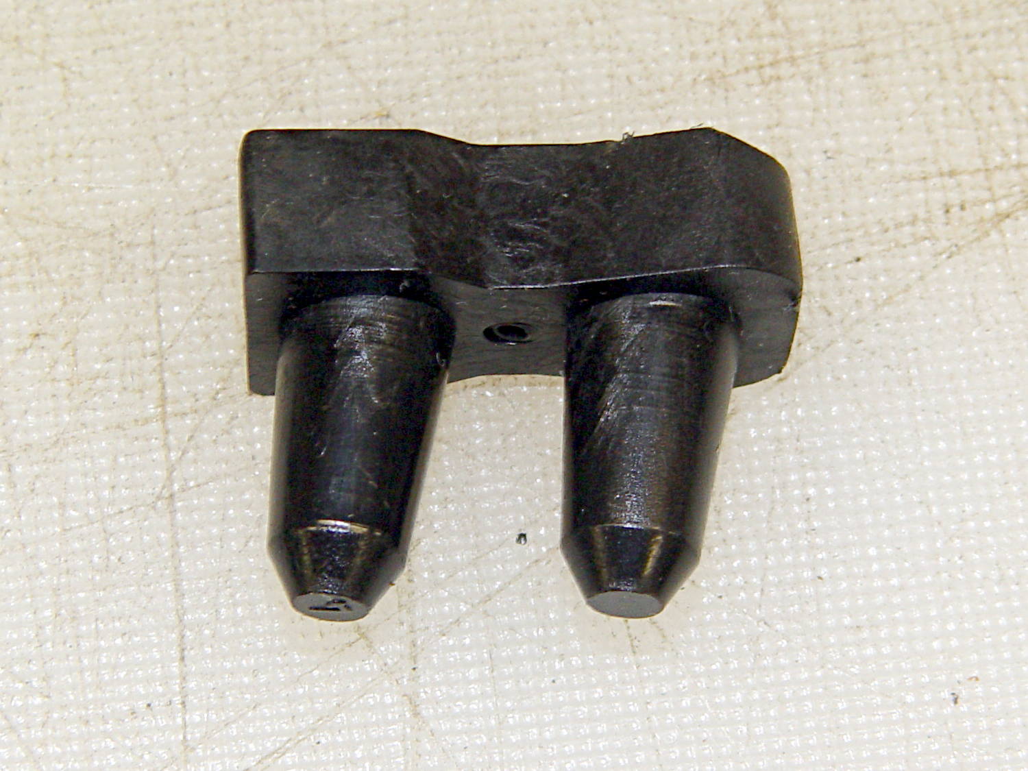
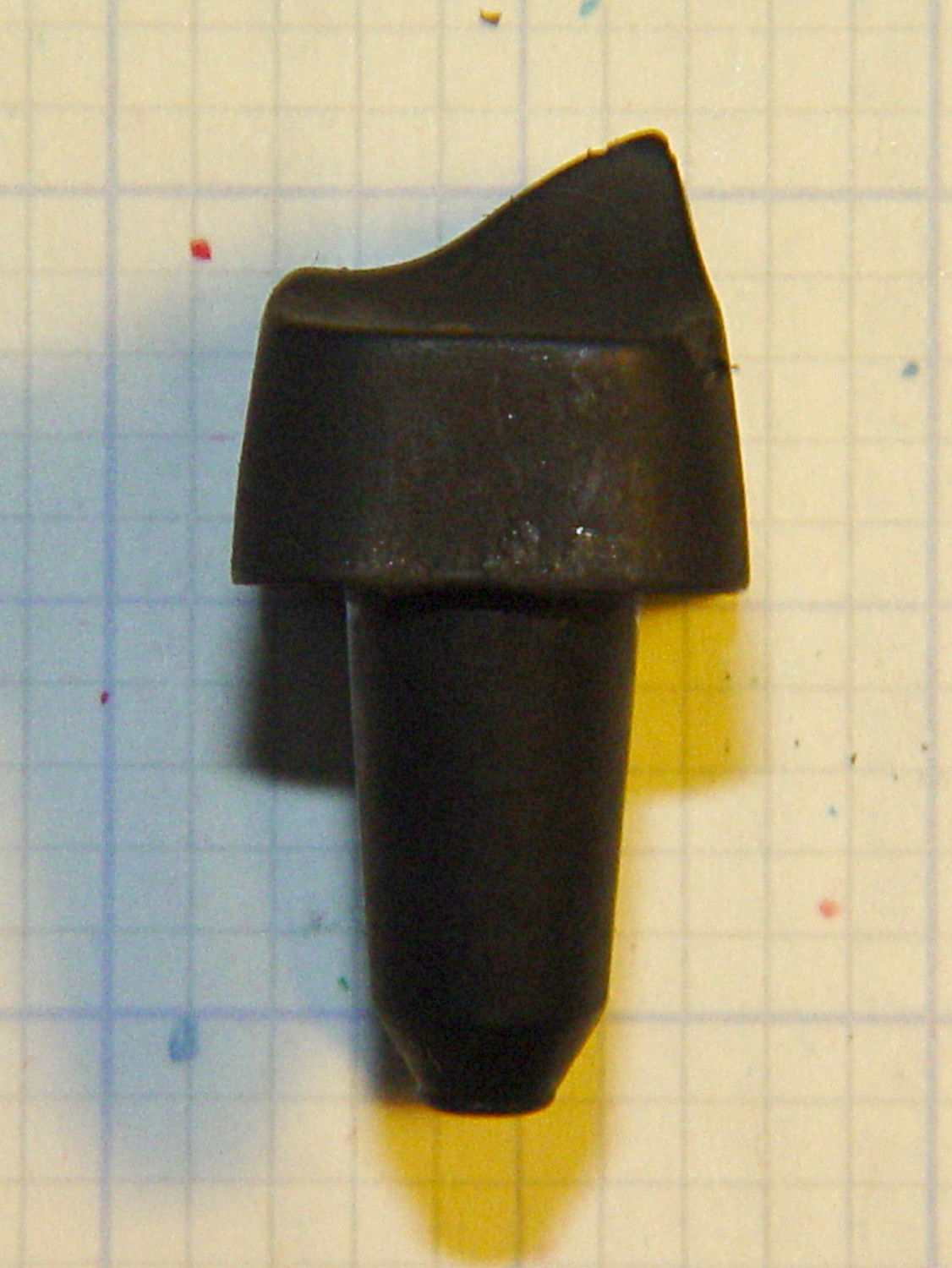
The top of the follower has a rather complex shape (yes, that’s a crunch toward the front of the ridge):

The front view shows more curves:
Judging from the online pictures, BHP followers have taken on a wide variety of shapes over the decades, so I’d expect almost anything would work more-or-less well.
The inner floor plate attaches to the spring and has a 5 mm dia x 1 mm tall boss that matches the hole in the outer floor plate:
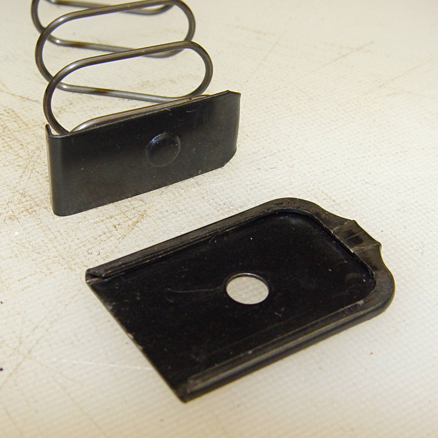
The hole in the outer floor plate is a scant 5.4 mm, just slightly under the head size of a 3.0×0.5 mm socket head cap screw. The OEM Browning magazines have a centered boss, but some aftermarket magazines move it a millimeter or so to the front or rear. The outer plate seems hard enough to be just about spring steel.
A tab on the front of the inner floor plate (to the left in this picture captures the spring:
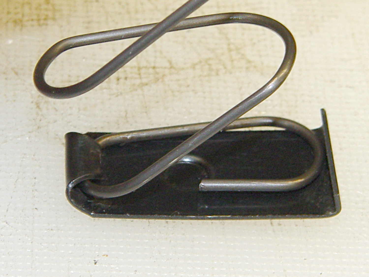
The inner plate is 0.75 mm mild steel and may be removable, depending on how tightly the tab got crunched during manufacturing. The tab extends a millimeter or so beyond the spring on the inside of the curve and is about 2 mm tall at that point.
The boss on the inner plate and the hole on the outer plate locate the spring at the proper position and also ensure the outer plate doesn’t accidentally slide off; you must push the boss inward to release the outer plate before sliding it forward. Using a rounded rod lets you push the inner plate far enough inward to release the spring pressure on the outer plate, making it much easier to slide; in fact, for my fingers, I can’t move the outer plate without inserting a rod in the hole.
The case is a seamless 0.7 mm thick high-carbon-steel tube with complex curves:
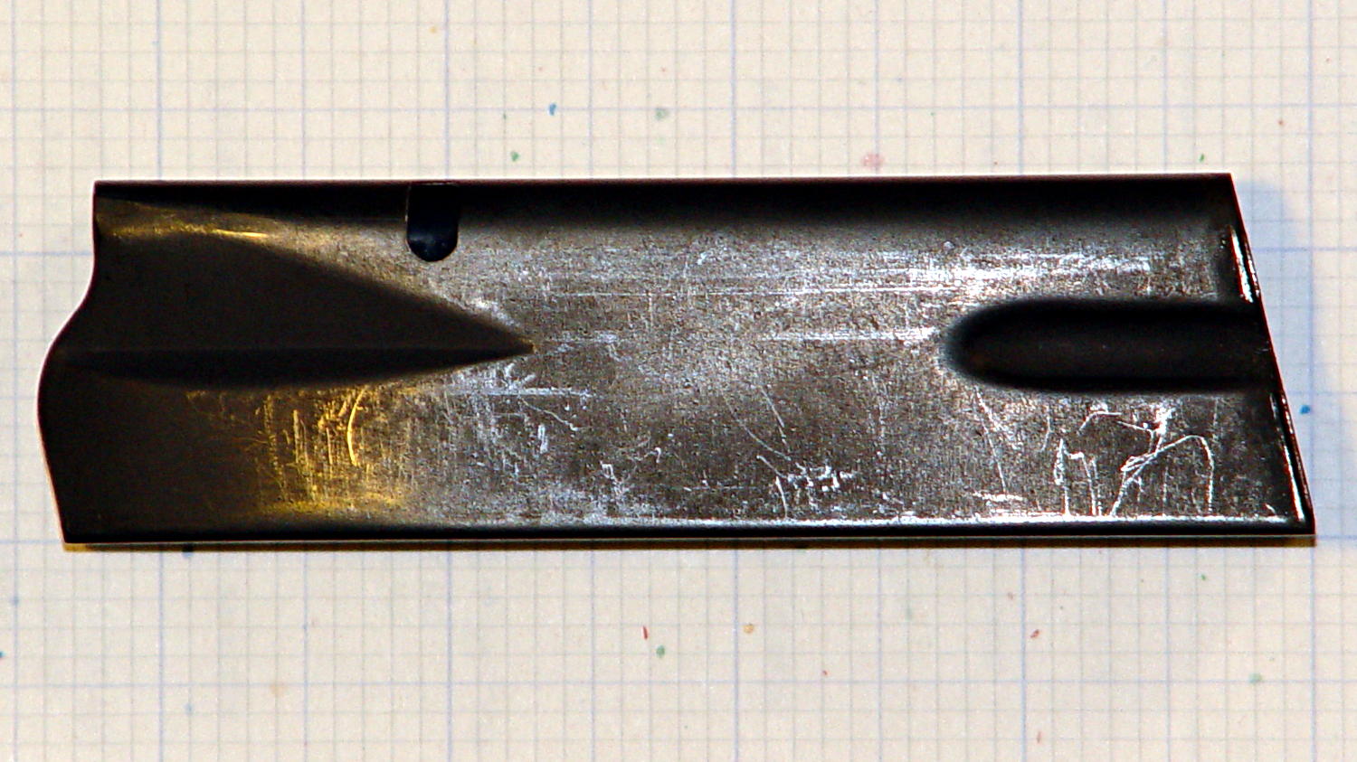
The “high carbon” part means that it’s not in the least bendy; a few operations on large presses mashed it into that shape and it’s not going to take on anything else by accident. The feed lips on the top can get bent if you abuse the thing, but that’s about it.
The case is 20.5 x 31.7 mm from the base to the latch hole, 99 mm long in front and 109 mm long in the back. The latch hole is 4.2 x 7.3 mm with a 2.7 mm notch in the front side, 67.2 mm from the base and 27.7 mm from the top. The angle of the case axis with respect to the bottom (on the right) is 12.5°.
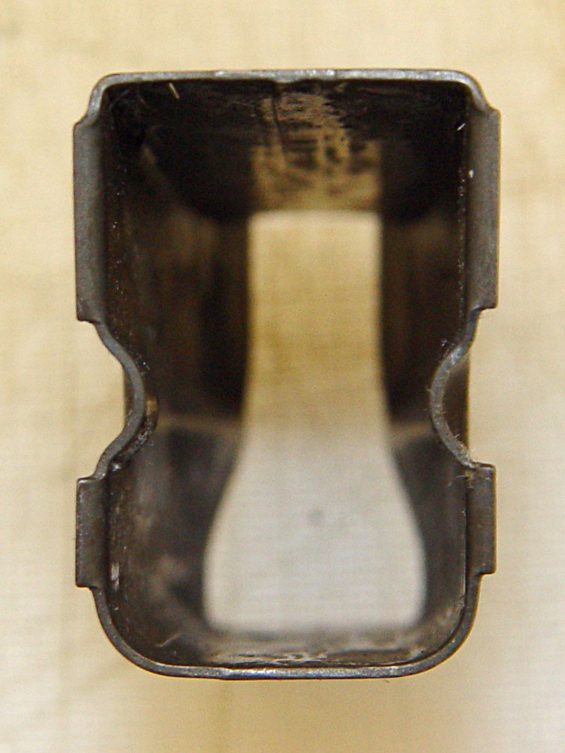
Inside measurements at the base: 30.5 x 18.7 mm. The rear corners are essentially right angles and the front curves fit 1/4 inch = 6.3 mm or 9/32 inch = 7.1 mm drills.
The lower flutes are 26 x 6.5 mm, centered on the side (even though it doesn’t look that way), and compress the outside of the case to 16.2 mm and the inside to 14.7 mm. The tabs engaging the outer floor plate are 23 mm edge-to-edge, 10.5 mm and 6.0 mm long, and protrude 1.5 mm from the outside of the case:
The top of the case is 10.5 mm wide at the rear of the feed lips, with the sharp bend 17.0 mm from the outside of the rear face:

The spring is 1.25 mm = 49 mil wire, 143 mm flat-to-flat high, about 15.1 mm turn-to-turn, 13/32 inch = 10.3 mm ID at the ends, 13.2 mm outside width, 25 mm inside length, and 27 mm outside length. Those don’t quite add up, but the whole thing is, well, springy.
The spring exerts these crudely measured forces:
- 1 round = 1.1 kg
- 10 rounds = 2.5 kg
The follower moves 5.3 mm, so the spring constant is very roughly 0.26 kg/mm = 14.8 pound/inch. Aftermarket springs tout their stiffness and come in 5% increments of additional force, so that’s probably not a critical number.
Limiting the capacity of a magazine so that it cannot be “readily” converted back to a higher capacity seems difficult, particularly if you allow disassembling the magazine for proper cleaning and maintenance. If operator safety and proper function isn’t a concern, then many things become possible.

Comments
5 responses to “Browning Hi-Power Magazine Dimensions”
I think working to change the legislature and ridiculous laws of your state would be a better option.
Remember that NY is where the Sullivan Laws started…
Disregarding the politics (and the opportunity for variable interpretations of the law), either a new follower or a “permanently” bonded spacer below the follower would be the best approach to limiting the mag capacity. I’d be worried about a printed follower, since some pistols are extremely sensitive to texture in the feed path, and that contour would be a momma-bear to begin with. (Maybe a molded bit that contacts the cartridge would work.).
Not always true for the 1911 family. I had purchased a 1911 (not a 1911A1) that spent a few decades in a WW-1 vintage holster. Had the pistol and its magazine parkerized. Took that mag to a pistol course at [redacted], since I was going to need a few mags. During part of an exercise I dropped the not-quite empty magazine to reload and clear a stovepipe jam. It found a strategically located rock and got an irrecoverable dent in it. The extra mass of the cartridges probably helped do the dent. Haven’t tried to reproduce the original situation, but never ran into problems while dropping empty magazines.
I’d worry about changing the spring dynamics with the reduced cartridge count, but the real problem could be that it doesn’t look like a “permanent” modification.
A block bonded to the interior floorplate that captures the spring could also be considered “readily restored”, but I want to explore that end of the, ahem, design space, because I can make it a lot more “permanent” without changing the dynamics.
Might require more than three pipes…
Warren Zevon’s “Lawyers, Guns and Money” comes to mind. Unfortunately, in this case, the state has have a surfeit of all three. [sigh]
Thanks for fixing my previous typo… [oops]