Ed Nisley's Blog: Shop notes, electronics, firmware, machinery, 3D printing, laser cuttery, and curiosities. Contents: 100% human thinking, 0% AI slop.
Pinning the top of Mary’s latest quilt used more than 1600 pins: three boxes of specialized quilting safety pins, plus straight quilting pins tucked into all the 3D printed / silicone filled caps. Less than a quarter of the quilt top fits on the table:
Quilt top with pins
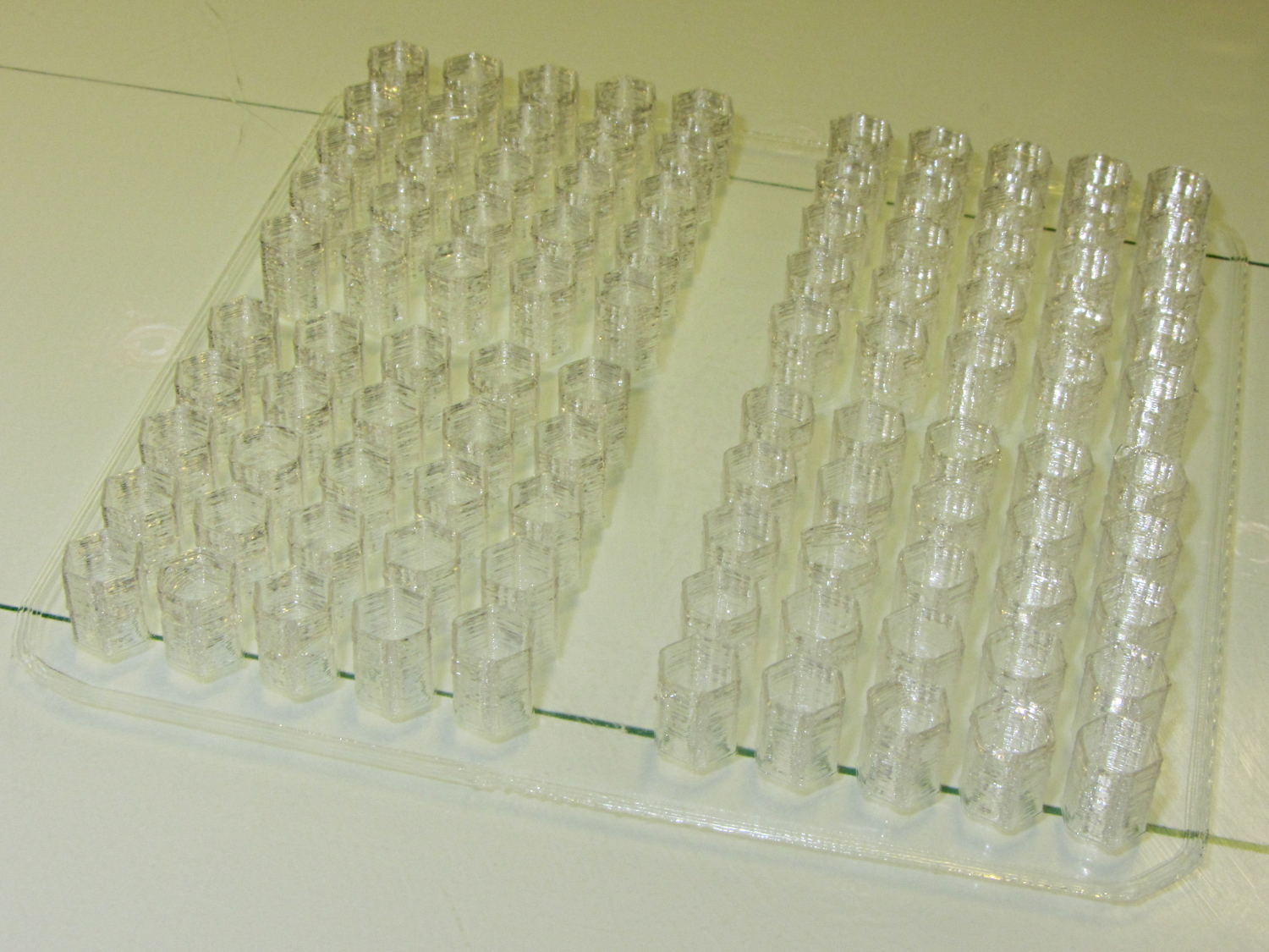
Although Mary doesn’t need them right now, I made another batch of 100 caps for her next project:
Quilting pin caps – 4 x 25 – on platform
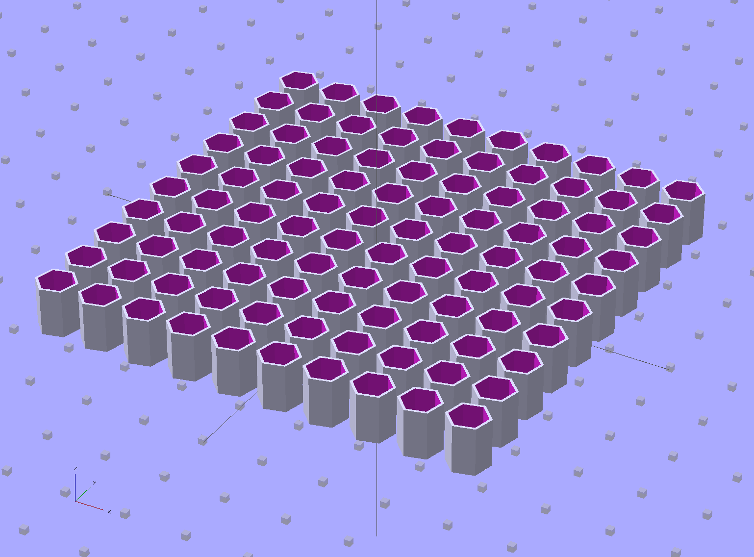
I tweaked the OpenSCAD source to build a 10×10 array:
Quilting Pin Cap – 10×10 array
But it turns out that a 5×5 array of caps, duplicated four times, works out better:
Quilting Pin Cap – 5×5 array
Slic3r takes far longer to process the larger array than to make four copies of the smaller array.
Half an hour later, they’re ready for silicone fill. In retrospect, natural PLA wasn’t a good choice for this job: there’s no way (for me) to take a picture of translucent silicone in crystalline PLA atop waxed paper on a white cutting board under fluorescent light…
On the upside, however, you can see exactly how far the pin goes into the cap:
With the platform and extruder starting at the 19.5 °C = 67 °F Basement Laboratory ambient …
The extruder takes 1 minute to reach 175 °C, overshoots to about 180 °C, crosses 175 °C going downward at 1:30, then gets up to 174 °C again at 3:15. I ran a PID tuning session quite a while ago with inconclusive results. Reducing the initial overshoot would probably increase the time-to-get-ready, with no net improvement.
The platform, which isn’t the stock Makergear hardware, requires 3:30 to reach 69 °C, just under the 70 °C target, at which point it’s ready to start. There’s no insulation under the PCB-trace heater, but some previous tinkering implies that running bare doesn’t make much difference, particularly with a fan blowing on the top surface of the glass.
Remember that’s with an outboard SSR to unload the RAMBo’s MOSFET.
By and large, the M2 is ready to print in under 5 minutes from a standing start, which is just about enough time to spritz hair spray on the platform, load the G-Code into Pronterface, and so forth and so on.
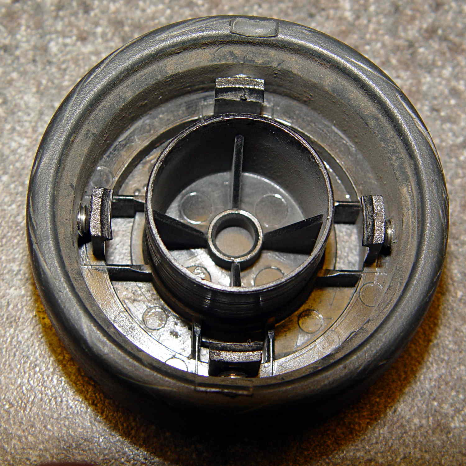
We still haven’t exhausted the never-sufficiently-to-be-damned Samsung Quiet Jet vacuum’s bag supply, so when a wheel fell off the floor brush again, I had to come up with a better fix than a twist of wire. Obviously, those delicate little retaining latches need more persuasion.
Capture the wheel in the Sherline’s 4-jaw chuck on the rotary table and drill four holes just below the end of the latches:
Samsung wheel – drilling
The wheel is 20 mm thick. The holes lie 9 mm back from the open end of the wheel or 11 mm from the closed end at the chuck face. Drill maybe 6 mm down; I did it by eye, jogging slowly downward until the tip of the drill touched the latch.
Tap the holes and install four 8-32 setscrews:
Samsung wheel – setscrews installed
I don’t have a bottoming tap, but an ordinary plug tap was Good Enough; the incomplete threads should hold the setscrews in place.
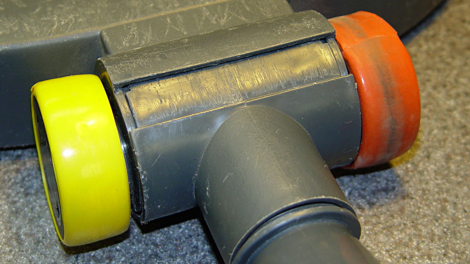
Reinstall the wheel, tighten the setscrews, and wrap festive silicone tape around the whole affair:
Samsung floor brush – wheel installed
I heroically resisted the temptation to pry the other wheel off for a preemptive repair …
Last week I gave a class at Squidwrench that helped bootstrap folks from new-to-Arduino to won’t-blow-it-up, showing how the I/O pins work in digital and analog mode with a bit of hands-on experimentation:
Potentiometer – analog input
We also covered some setup, how the whole compiler thing works, and suchlike.
The parts kit contains a 10 kΩ pot (with detents!), a green LED (with resistor!), and a jumper that serves as both a switch and a short antenna for an input without a pullup. They’re all terminated in header pins with heatstink tubing for strain relief.
The ZIP file with all the source code (ArduinoIOIntro-2014-06.zip.odt) masquerades as an OpenDocument text file, because WordPress prohibits ZIP files. Just rename it to remove the ODT suffix, unzip it, and there you are. It also includes the PDF, because none of the Arduino files have any comments at all…
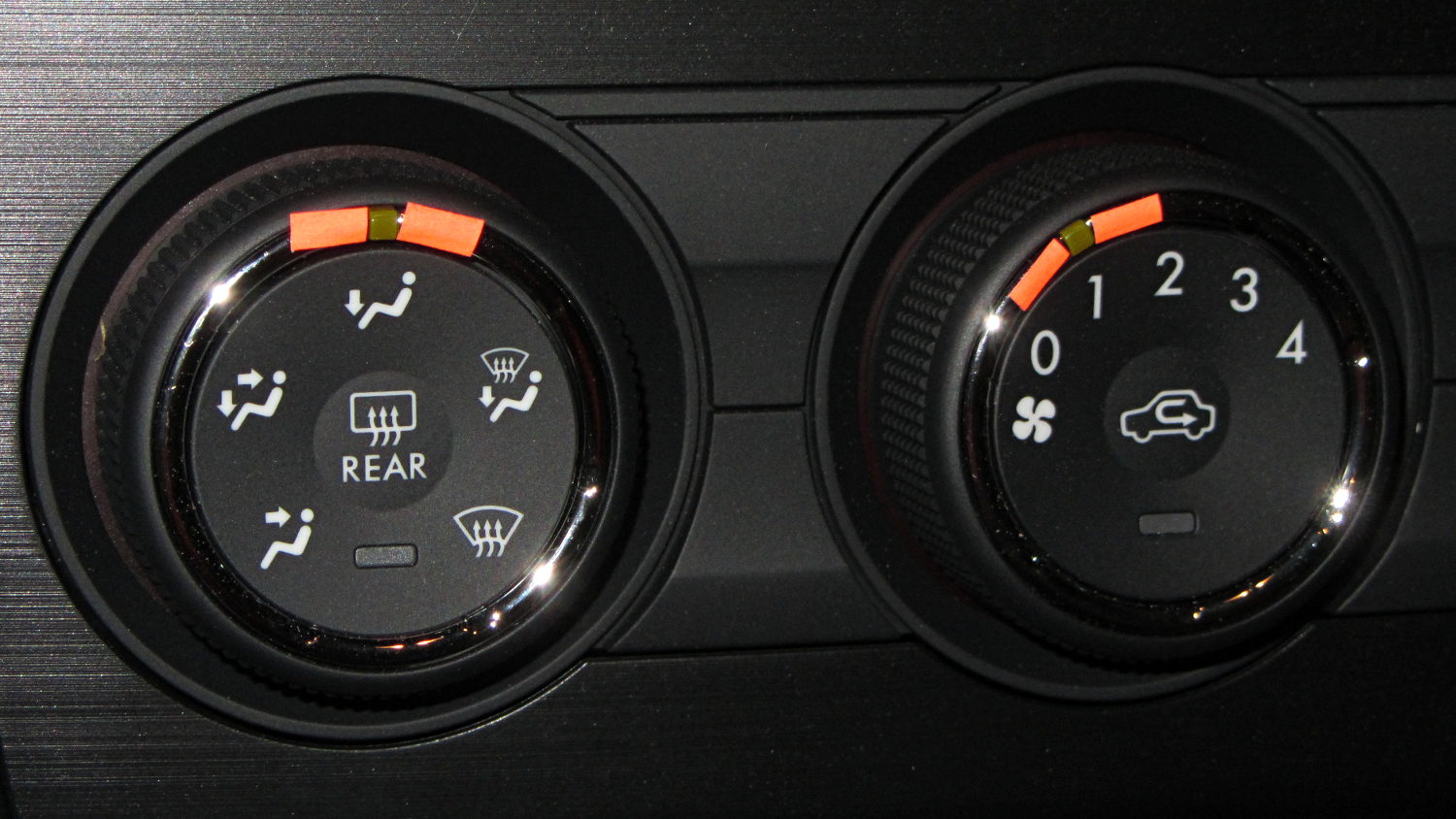
Our Forester has three knobs that control air direction / speed / temperature. Knobs are much better than buttons, because you can adjust them without looking. At least, that’s the ideal situation.
Here’s the setting for airflow to the footwell:
Subaru Forester – Airflow knob – feet – daylight
Here’s what it looks like with airflow to the cabin:
Subaru Forester – Airflow knob – face – daylight
The knob has no tactile position indicator. That greenish rectangle, located in one of seven symmetric dimples that camouflage its position, is barely visible in normal light, invisible with sunglasses, and not apparent to the touch.
Well, if conspicuous is what you want, I can fix that:
Subaru Forester – knobs – highlighted
Fluorescent tape will fade quickly, but it’ll last until something better comes along. Perhaps a small pointer epoxied onto the knurled surface, extending around to the indicator?
During one of my recent presentations, somebody asked about the accuracy of 3D printed parts, which reminded me of another member of Coasterman’s Essential Calibration Set: the perimeter width/thickness test block. Back in the day, calibrating the extruder meant getting the actual ratio of the thread width to its thickness to match the ideal value you told Skeinforge to use; being a bit off meant that the final dimensions weren’t quite right.
But when I got it right, the Thing-O-Matic printed a test block with considerable success, despite the horrible retraction zittage:
Perimeter Calibration Block – yellow 1.10 rpm 0.33 0.66 mm
Alas, feeding the STL to Slic3r showed that it was grossly non-manifold, and none of the automated repair programs produced good results. Turns out it’s an STL created from a Sketchup model, no surprise there, and the newer slicers seem less tolerant of crappy models.
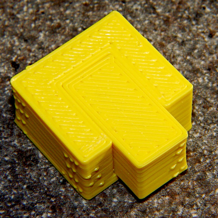
Sooo, here’s a new version built with OpenSCAD:
Fit Test Blocks – build view
You get three blocks-and-plugs at once, arranged in all the useful orientations, so you can test all the fits at the same time. They come off the platform about like you’d expect:
Fit test blocks
I tweaked the code to make the plugs longer than you see there; the short ones were mighty tough to pry out of those slots.
I ran the plugs across a fine file to clean the sides, without removing any base material, and the plugs fit into the slots with a firm push. I’d do exactly the same thing for a CNC milled part from the Sherline, plus breaking the edges & corners.
The plugs doesn’t fit exactly flush in the recesses for the two models on the right side of that first image, because the edges and corners aren’t beveled to match each other. It’s pretty close and, if it had to fit exactly, you could make it work with a few more licks of the file. The left one, printed with the slot on the top surface, fits exactly as flush as the one from the Thing-O-Matic.
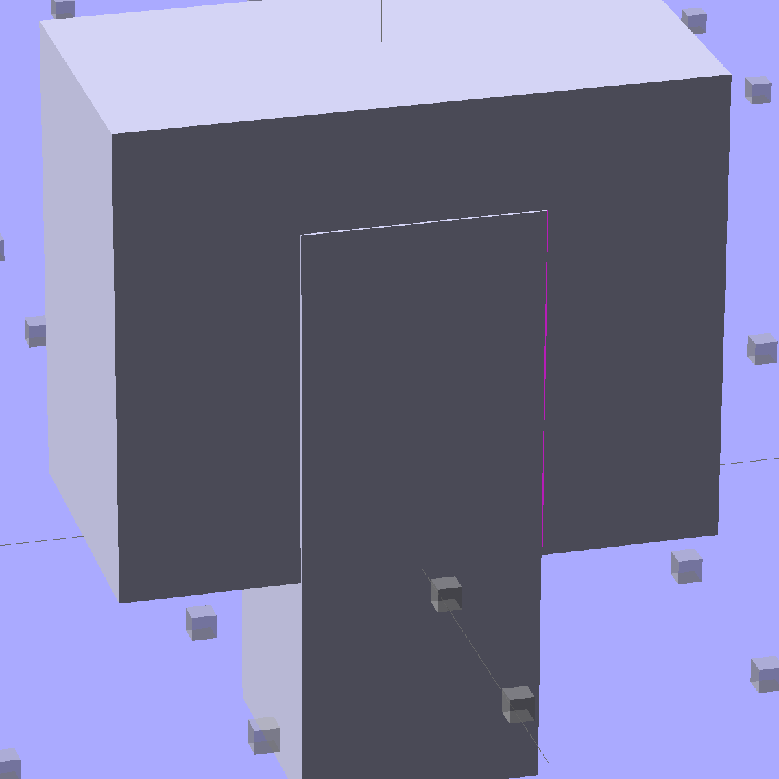
Of course, there’s a cheat: the model allows 0.1 mm of internal clearance on all sides of the plug:
Fit Test Block – show view
The outside dimensions of all the blocks and plugs are dead on, within ±0.1 mm of nominal. You’d want to knock off the slight flange at the base and bevel the corners a bit, but unless it must fit inside something else, each object comes off the platform ready to use.
Feel free to dial that clearance up or down to suit your printer’s tolerances.
The OpenSCAD source code:
// Fit test block based on Coasterman's perimeter-wt.stl
//	http://www.thingiverse.com/thing:5573
//	http://www.thingiverse.com/download:17277
// Ed Nisley - KE4ZNU - May 2014

Layout = "Show";

//- Extrusion parameters must match reality!
//  Print with 2 shells and 3 solid layers

ThreadThick = 0.20;
ThreadWidth = 0.40;

Protrusion = 0.1;			// make holes end cleanly

function IntegerMultiple(Size,Unit) = Unit * ceil(Size / Unit);

//----------------------
// Dimensions

Clearance = 0.1;

PlugSize = [10.0,10.0,25.0];
BlockSize = [25.0,13.0,20.0];

PlugOffset = 10.0;

//----------------------
// Useful routines

module ShowPegGrid(Space = 10.0,Size = 1.0) {

  RangeX = floor(100 / Space);
  RangeY = floor(125 / Space);

	for (x=[-RangeX:RangeX])
	  for (y=[-RangeY:RangeY])
		translate([x*Space,y*Space,Size/2])
		  %cube(Size,center=true);

}

module Block() {
	difference() {
		translate([0,0,BlockSize[2]/2])
			cube(BlockSize,center=true);
		translate([0,PlugSize[1] - PlugSize[1]/2 - BlockSize[1]/2,-PlugOffset])
			Plug(Clearance);
	}
}

module Plug(Clear = 0.0) {
	minkowski() {
		translate([0,0,PlugSize[2]/2])
			cube(PlugSize,center=true);
		if (Clear > 0.0)
			cube(Clear,center=true);
	}
}

//----------------------
// Build it

ShowPegGrid();

if (Layout == "Block")
	Block();

if (Layout == "Plug")
	Plug();

if (Layout == "Show") {
	Block();
	translate([0,PlugSize[1] - PlugSize[1]/2 - BlockSize[1]/2,-PlugOffset])
		Plug();
}

if (Layout == "Build") {
	Block();
	translate([0,-15,0])
		Plug();

	translate([-30,0,0]) {
		translate([0,-BlockSize[1]/2,BlockSize[1]/2])
			rotate([-90,0,0])
				Block();
		translate([-PlugSize[2]/2,-15,PlugSize[0]/2])
			rotate([0,90,0])
				Plug();
	}

	translate([30,0,0]) {
		translate([0,0,BlockSize[2]])
			rotate([180,0,180])
				Block();
		translate([-PlugSize[2]/2,-15,PlugSize[1]/2])
			rotate([90,0,90])
				Plug();
	}

}
The Boneheads Raven Skull demo came out reasonably well, albeit in a reduced size, on the Squidwrench Frank-o-Squid:
TOM286 – Raven Skull on platform
So I ran off a full-size version on the M2 for comparison:
Raven Skull – on M2 platform
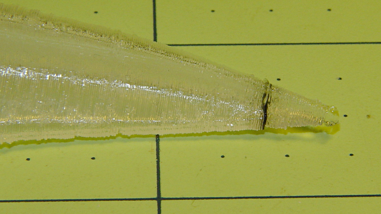
The extruder apparently contained a gobbet of black PLA, left over from the Pink Panther Woman, that managed to hang on inside until the very tip of the beak:
Raven Skull – beak contamination
Close inspection found two black strands closer to the base of the printed parts:
Raven Skull – black contamination
The rear of the skull joins the front just behind the eye sockets, where the solid bottom layers make a visible contrast with the air behind the perimeter threads elsewhere. Refraction darkens some of the threads, but the two black patches stand out clearly.
If it weren’t natural PLA, those flaws wouldn’t be nearly so noticeable.
Were I doing this stuff for a living, I might dedicate a hot end (or an entire extruder) to each color and be done with it.
All in all, the printed quality is about as good as I could expect from a glorified glue gun.
The extreme slowdown while printing the tip of the beak pushed Pronterface’s remaining time estimate over the edge: