The Smell of Molten Projects in the Morning

Ed Nisley's Blog: Shop notes, electronics, firmware, machinery, 3D printing, laser cuttery, and curiosities. Contents: 100% human thinking, 0% AI slop.

Category: Machine Shop

Mechanical widgetry

  • Improved Chain Mail Link

    The rectangular posts in my chain mail resemble Zomboe’s original design, but with dimensions computed directly from the bar (and, thus, thread) widths and thicknesses to ensure good fill and simple bridging:

    Chain Mail Link
    Chain Mail Link

    They fit together well, but the angled post edges make the bridge threads longer than absolutely necessary along the outside edge of each link:

    Chain Mail Sheet - detail
    Chain Mail Sheet – detail

    A bit of fiddling produces a squared-off version:

    Chain Mail Link - Improved Posts
    Chain Mail Link – Improved Posts

    Which nest together like this:

    Chain Mail - Improved Posts - Bottom View
    Chain Mail – Improved Posts – Bottom View

    Now all the bridge threads have the same length, which should produce better results.

    The OpenSCAD source code for the link:

    module BaseLink() {
    
    	render(convexity=2)
    		difference() {
    			translate([0,0,BaseHeight/2]) {
    				difference(convexity=2) {
    					intersection() {		// outside shape
    						cube([BaseSide,BaseSide,BaseHeight],center=true);
    						rotate(45)
    							cube([BaseOutDiagonal,BaseOutDiagonal,BaseHeight],center=true);
    					}
    					intersection() {		// inside shape
    						cube([(BaseSide - 2*BarWidth),
    							  (BaseSide - 2*BarWidth),
    							  (BaseHeight + 2*Protrusion)],
    							 center=true);
    						rotate(45)
    							cube([BaseInDiagonal,
    								  BaseInDiagonal,
    								  (BaseHeight +2*Protrusion)],
    								 center=true);
    					}
    				}
    			}
    
    			translate([0,0,(BaseHeight/2 + BarThick)])
    				cube([(BaseSide - 2*BarWidth - 2*BarWidth/sqrt(2)),
    					  (2*BaseSide),
    					  BaseHeight],
    					 center=true);
    			translate([0,0,(BaseHeight - BaseHeight/2 - BarThick)])
    				cube([(2*BaseSide),
    					  (BaseSide - 2*BarWidth - 2*BarWidth/sqrt(2)),
    					  BaseHeight],
    					 center=true);
    		}
    }
    
  • Hotrod M2 Platform Support Stud Repair

    The hotrod build platform I’m using with the Makergear M2 consists of a PCB heater bonded to a glass plate, supported by three socket head cap screws soldered into the PCB. The print quality recently took a nosedive that seemed related to the first layer height, with which I fiddled more than usual, and finally the front of the platform became obviously, visibly, no-way-around-it far too high. Peering under the platform showed that the front support stud had pulled out of the solder fillet securing it to the PCB:

    M2 Hotrod Platform - support stud pullout
    M2 Hotrod Platform – support stud pullout

    Those PCB patterns conduct the heater current around the mounting holes: the hotrod platform has better heat distribution than the OEM M2 platform.

    The offending screw didn’t go anywhere:

    M2 Hotrod Platform - support stud in spring
    M2 Hotrod Platform – support stud in spring

    The wavy spring and silicone plug press on the PCB, so the solder fillet had to support all the stress. It seemed as though the solder hadn’t bonded to the stainless SHCS, but, rather than try to fix that, I decided to put a washer on the screw. That way, the spring bears on the washer and the screw head supports the strain, with the solder fillet responsible for holding the PCB and glass plate in position.

    Alas, I didn’t have any washers small enough on the inside (3 mm) and big enough on the outside to support the springs, so I cut some out of a sheet steel scrap by drilling the center hole to the proper diameter, then applying a hole saw without its (far too large) pilot drill:

    M2 Hotrod Platform - hole-sawing washers
    M2 Hotrod Platform – hole-sawing washers

    That’s a lethally bad idea, as the pilot-less saw can grab the sheet and toss it across the shop. Notice the screws holding the sheet down and absorbing the cutting torque, plus the two clamps enforcing the “stay put” edict.

    The other problem with not having a pilot drill in the hole saw is that it’s not guaranteed to cut a cookie that’s concentric with the center hole. Instead of taking the time to make a pilot, I just drilled and cut a few extra washers, then picked the best three of the set for finishing:

    M2 Hotrod Platform - rough-cut washers
    M2 Hotrod Platform – rough-cut washers

    Using a screw as a mandrel, I lathe-turned the OD of the better ones to make them nice and round:

    M2 Hotrod Platform - washer on mandrel
    M2 Hotrod Platform – washer on mandrel

    Two of the three PCB support screws were in the right place (they hadn’t come loose), so I used the M2 as an alignment fixture for the third:

    M2 Hotrod Platform - aligning washers
    M2 Hotrod Platform – aligning washers

    That’s a layer of  good old JB Industro Weld epoxy, rated for much higher temperatures than the platform will ever see, between the big washers and the PCB. I buttered up the head of the errant screw and the inside of the solder fillet, shoved it in, and then stacked everything together. The small washers held the big washers perpendicular to the screws while the epoxy cured.

    After that, I removed the small washers, reinstalled springs + silicone plugs, tightened the nyloc nuts, aligned the platform, ran off a few thinwall hollow boxes, tweaked the alignment, and it was all good:

    M2 Hotrod Platform - thinwall box alignment
    M2 Hotrod Platform – thinwall box alignment

    The rest of the story: that mumble screw pulled loose on the Friday evening before the Mini Maker Faire on Saturday morning. I did all the shop work after supper, then let the epoxy cure overnight with the platform set to 95 °F while I got a good night’s sleep. Reinstalling and realigning the platform took the better part of half an hour around breakfast, after which I tore it all down, packed it all up, and headed off to the Mini Maker Faire.

    In truth, that’s the most trouble I’ve had with the M2 and it’s not Makergear’s fault: it’s not their platform. After reinstalling the platform, the alignment was no big deal and it’s been stable ever since.

  • Sony HDR-AS30V Audio: Fake Fur FTW!

    A scrap of fake fur cut to fit the outline of the Sony HDR-AS30V helmet camera and stuck in place with a square of double-stick foam centered above (or below, in the normal orientation) the lens:

    Sony HDR-AS30V - fake fur installed
    Sony HDR-AS30V – fake fur installed

    Snippy remarks about what that looks like will not be tolerated, m’kay?

    It reduces wind noise to an occasional rumble from strong gusts and even those don’t crush the AGC. My side of our radio conversations became clearly audible, as did shifters clicking and gravel crunching. There’s still plenty of noise, but now it comes from actual sound sources that don’t overwhelm the amp.

    A layer of ordinary adhesive tape still covers the mic pores and the fur’s fabric backing extends over the tape, so the combination must muffle the sound at least a little bit. Given the source material and my hearing, it’s Good Enough; Golden Eared Audiophiles need not apply.

    I also cannot detect any difference between the left and right audio channels, so the stereo separation at 15 mm isn’t worth much. I don’t know if the camera swaps the audio channels in video flip mode; that would be a nice touch.

    The hairs extending outward beside the lens occasionally blew into view, so a haircut is in order:

    mah00242-075 - Fake Fur in view
    mah00242-075 – Fake Fur in view

    Perhaps a clip that snaps over the skeleton frame to hold a neat patch of fur in place without adhesive on the camera body would be even better?

  • 3D Printed Chain Mail Again

    Everybody likes chain mail, so I made a few big sheets:

    Chain Mail Sheet
    Chain Mail Sheet

    That’s a nominal 150 mm on the X axis and 200 mm on the Y, which pretty well fills the M2’s 8×10 inch platform after Slic3r lays a few skirt threads around the outside. All 192 links require a bit under four hours to print: all those short movements never let the platform get up to full speed.

    Look no further for a brutal test of platform alignment and adhesion. The platform is slightly too high in the left front corner and, no surprise, slightly too low in the right rear. The skirt thread varies from 0.15 to 0.27 around the loop.

    Hairspray works wonder to glue down all those little tiny links. They pop off the platform quite easily after it cools under 50 °C, with no need for any post-processing.

    This version of the OpenSCAD code correctly figures the number of links to fill a given width & length; the old code didn’t get it quite right.

    Coloring the links makes the whole thing easier to look at:

    Chain Mail Sheet - detail
    Chain Mail Sheet – detail

    The real world version comes out in red PLA that saturates Sony imagers:

    Chain Mail - flexed
    Chain Mail – flexed

    It really is that flexible!

    The OpenSCAD source code:

    // Chain Mail Sheet
    // For Slic3r and M2 printer
    // Ed Nisley KE4ZNU - Apr 2013
    //   Oct 2013 - larger links, better parameterization
    //   Nov 2014 - fix size calculation, add coloration
    
    Layout = "Show";			// Link Build Show
    
    //-------
    //- Extrusion parameters must match reality!
    //  Print with +0 shells and 6 solid layers
    
    ThreadThick = 0.20;
    ThreadWidth = 0.40;
    
    HoleWindage = 0.2;
    
    Protrusion = 0.1;			// make holes end cleanly
    
    function IntegerMultiple(Size,Unit) = Unit * ceil(Size / Unit);
    
    //-------
    // Dimensions
    
    BarThreads = 6;
    BarWidth = BarThreads * ThreadWidth;
    
    BarThick = 4 * ThreadThick;
    
    LinkSquare = IntegerMultiple(2.5*BarThreads,ThreadWidth);
    LinkHeight = 2*BarThick + 4*ThreadThick;           // bars + clearance
    
    echo(str("Link height: ",LinkHeight));
    
    LinkOutDiagonal = LinkSquare*sqrt(2) - BarWidth;
    LinkInDiagonal = LinkSquare*sqrt(2) - 2*(BarWidth/2 + BarWidth*sqrt(2));
    
    echo(str("Outside diagonal: ",LinkOutDiagonal));
    
    LinkSpacing = 0.60 * LinkOutDiagonal;		// totally empirical
    echo(str("Link spacing: ",LinkSpacing));
    
    SheetSizeX = 150;
    SheetSizeY = 200;
    
    NumLinksX = floor((SheetSizeX - LinkOutDiagonal) / LinkSpacing) + 1;
    NumLinksY = floor((SheetSizeY - LinkOutDiagonal) / LinkSpacing) + 1;
    
    echo(str("Links X: ",NumLinksX," Y: ",NumLinksY," Total: ",NumLinksX*NumLinksY));
    
    //-------
    
    module ShowPegGrid(Space = 10.0,Size = 1.0) {
    
      RangeX = floor(95 / Space);
      RangeY = floor(125 / Space);
    
    	for (x=[-RangeX:RangeX])
    	  for (y=[-RangeY:RangeY])
    		translate([x*Space,y*Space,Size/2])
    		  %cube(Size,center=true);
    
    }
    
    //-------
    // Create basic link
    
    module Link() {
        render()
    	rotate(45)
    		difference(convexity=2) {
    			translate([0,0,LinkHeight/2]) {
    				difference(convexity=2) {
    					intersection() {		// outside shape
    						cube([LinkSquare,LinkSquare,LinkHeight],center=true);
    						rotate(45)
    							cube([LinkOutDiagonal,LinkOutDiagonal,LinkHeight],center=true);
    					}
    					intersection() {		// inside shape
    						cube([(LinkSquare - 2*BarWidth),(LinkSquare - 2*BarWidth),(LinkHeight + 2*Protrusion)],center=true);
    						rotate(45)
    							cube([LinkInDiagonal,LinkInDiagonal,(LinkHeight +2*Protrusion)],center=true);
    					}
    				}
    			}
    			for (i=[-1,1]) {				// create bars
    				translate([0,-i*(sqrt(2)*BarWidth/2),BarThick])
    					rotate(45 + 180*(i+1)/2)
    						cube([LinkOutDiagonal,LinkOutDiagonal,LinkHeight]);
    				translate([i*(sqrt(2)*BarWidth/2),0,-BarThick])
    					rotate(135 + 180*(i+1)/2)
    						cube([LinkOutDiagonal,LinkOutDiagonal,LinkHeight]);
    			}
    		}
    }
    
    //-------
    // Build it!
    
    ShowPegGrid();
    
    if (Layout == "Link") {
      Link();
    
    }
    
    if (Layout == "Build" || Layout == "Show") {
    	for (ix=[-(NumLinksX/2 - 0):(NumLinksX/2 - 1)])
    		for (iy=[-(NumLinksY/2 - 0):(NumLinksY/2 - 1)])
    			translate([ix*LinkSpacing + LinkSpacing/2,iy*LinkSpacing + LinkSpacing/2,0])
    				if (Layout == "Show")
    					color([0.5+(ix/NumLinksX),0.5+(iy/NumLinksY),1.0]) Link();
    				else Link();
    }
    
  • Trust Multimedia Mouse: Gummy Rubber

    While looking for something else, I found the old Trust Multimedia Mouse and discovered its nice grippy rubber surfaces had become adhesive slime. Graduated efforts with water, rubbing alcohol, and denatured alcohol being unavailing, I finally hit it with xylene and that did the trick:

    Degummed Trust Mouse
    Degummed Trust Mouse

    Of course, xylene also wiped away the fancy button markings and irretrievably scarred the surface, but at least I can pick the mouse up without having it stick to my hand. Not that I pick it up that often, obviously.

    Several other gadgets have a similar grippy finish, so now I know what to do when it turns gummy: throw the gadgets out…

  • Shimano SPD Pedals: Cleat Oilers

    Here’s the solution to creaking SPD pedals due to hardened shoe cleats gritting on hardened pedal latches:

    Shimano SPD pedal - cleat oiler
    Shimano SPD pedal – cleat oiler

    Those are carefully shaped snippets of open-cell foam tucked around the springs under the movable latches, loaded with a few drops of penetrating oil, and ridden for several months. Nary a squeak or grinding sound has emerged: far better than the results after I added a drop of oil whenever either of us heard that sound.

    Similar snippets tucked under the forward latch fell out without affecting the results, from which I conclude:

    • The front latch doesn’t squeak
    • The foam on the other side is Close Enough
    • Penetrating oil oozes into a thin film over the whole pedal

    The cleats don’t quite touch the ground when we walk, so we’re not leaving oily footprints.

    Should I ever install new pedals, I’ll see if a larger foam block can span the gap between the front latch on the top and the movable latch on the bottom.

  • Eyeglass Temple Spring Repair

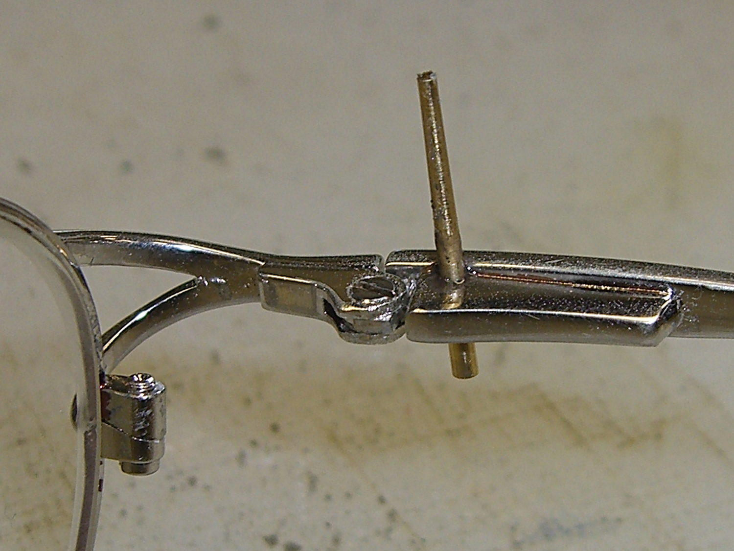
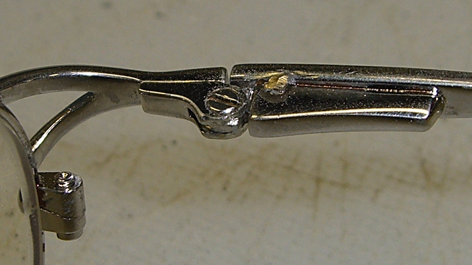
    Another of Mary’s glasses snapped at the temple joint:

    Broken eyeglass temple spring
    Broken eyeglass temple spring

    This one has a spring inside the joint that latches the temple on either side of that square inner corner. Obviously, there’s no way to reconnect the broken stub with the spring retracted inside the brazed temple box, so:

    • File off the corner
    • Fill the socket with epoxy
    • Ease the stub in place
    • Wipe off the excess epoxy
    • Align on the workbench
    • Let it cure overnight

    At least the hinge folds again, even if the spring doesn’t work:

    Broken eyeglass temple spring - epoxied
    Broken eyeglass temple spring – epoxied

    She promises to scrap out her oldest glasses after the next eye exam…